US6850654B2 - Passive thermal compensation of all-fiber Mach-Zehnder interferometer - Google Patents
Passive thermal compensation of all-fiber Mach-Zehnder interferometer Download PDFInfo
- Publication number
- US6850654B2 US6850654B2 US10/258,913 US25891302A US6850654B2 US 6850654 B2 US6850654 B2 US 6850654B2 US 25891302 A US25891302 A US 25891302A US 6850654 B2 US6850654 B2 US 6850654B2
- Authority
- US
- United States
- Prior art keywords
- fiber
- arms
- mzi
- segment
- couplers
- Prior art date
- Legal status (The legal status is an assumption and is not a legal conclusion. Google has not performed a legal analysis and makes no representation as to the accuracy of the status listed.)
- Expired - Lifetime
Links
Images


Classifications
-
- G—PHYSICS
- G02—OPTICS
- G02B—OPTICAL ELEMENTS, SYSTEMS OR APPARATUS
- G02B6/00—Light guides; Structural details of arrangements comprising light guides and other optical elements, e.g. couplings
- G02B6/24—Coupling light guides
- G02B6/26—Optical coupling means
- G02B6/28—Optical coupling means having data bus means, i.e. plural waveguides interconnected and providing an inherently bidirectional system by mixing and splitting signals
- G02B6/293—Optical coupling means having data bus means, i.e. plural waveguides interconnected and providing an inherently bidirectional system by mixing and splitting signals with wavelength selective means
- G02B6/29346—Optical coupling means having data bus means, i.e. plural waveguides interconnected and providing an inherently bidirectional system by mixing and splitting signals with wavelength selective means operating by wave or beam interference
- G02B6/2935—Mach-Zehnder configuration, i.e. comprising separate splitting and combining means
- G02B6/29352—Mach-Zehnder configuration, i.e. comprising separate splitting and combining means in a light guide
-
- G—PHYSICS
- G02—OPTICS
- G02B—OPTICAL ELEMENTS, SYSTEMS OR APPARATUS
- G02B6/00—Light guides; Structural details of arrangements comprising light guides and other optical elements, e.g. couplings
- G02B6/24—Coupling light guides
- G02B6/26—Optical coupling means
- G02B6/28—Optical coupling means having data bus means, i.e. plural waveguides interconnected and providing an inherently bidirectional system by mixing and splitting signals
- G02B6/293—Optical coupling means having data bus means, i.e. plural waveguides interconnected and providing an inherently bidirectional system by mixing and splitting signals with wavelength selective means
- G02B6/29379—Optical coupling means having data bus means, i.e. plural waveguides interconnected and providing an inherently bidirectional system by mixing and splitting signals with wavelength selective means characterised by the function or use of the complete device
- G02B6/29398—Temperature insensitivity
Definitions
- This invention relates to a Mach-Zehnder interferometer, which has two fused-fiber couplers, interconnected by two optical fibers that provide both a phase shift and a thermal compensation for the interferometer.
- MZI Mach-Zehnder interferometer
- All-fiber Mach-Zehnder interferometers typically include two optical couplers separated by a phase shift region, which comprises two optical fibers that interconnect, said couplers.
- the two fibers which are often referred to as “arms” have different optical path lengths so that optical signals propagate through them at different velocities in the phase shift region.
- Light launched into the device passes through the first coupler where it is split and led through the pair of optical fibers. Both lightwaves are then coupled again by the second coupler and taken out as an optical signal output from the two output ports of the second coupler.
- the light portions recombining at the second coupler are in phase, they constructively interfere at one of the output ports of the second coupler; if they are not in phase, in particular if the two light portions incur a ⁇ differencing phase shift, they combine constructively at the other output port of the second coupler.
- Mach-Zehnder interferometers are known for their narrow band capabilities. For example, they can be used in dense wavelength division multiplexer (DWDM) optical communication systems. For this purpose, they must be stable over a range of environmental conditions, such as temperatures, within a defined range, and during presence of temperature variations.
- DWDM dense wavelength division multiplexer
- the refractive indices or the optical path lengths of the two connecting fibers of the device between the two couplers will usually vary with temperature. If the temperature dependence of the indices of refraction of the two fibers is not equal or if the optical paths of the two fibers are not equal, the temperature variations will cause variations in the differential phase shift.
- the channel spacing of the device defined as the wavelength separation between the transmission peaks of wavelengths of two adjacent channels, as well as the wavelength peaks and passband, become unstable, which causes significant problems for DWDM applications due to the small separation between channels in DWDMs.
- MZ-type interferometer devices In view of the importance of MZ-type interferometer devices, it is highly desirable to have available such devices that can exhibit stable performance even in the presence of some thermal disturbances. This can be achieved by compensating for the temperature induced shift so as to maintain the optical path length difference unchanged as the temperature varies.
- U.S. Pat. No. 4,725,141 provides an all-fiber MZI with connecting fibers or arms between the couplers being of equal length and located close to each other, thus ensuring that the effects of temperature changes are minimized since both arms are equally affected by temperature variations.
- the connecting arms must be made of the same material and to achieve the required phase shift a transducer is coupled to at least one of the interferometer arms, which is not a very practical feature.
- U.S. Pat. No. 6,118,909 discloses a different manner by which optical devices having a plurality of waveguides of differing lengths, such as wavelength routers, may be treated to achieve improved temperature independence. This is done by applying a temperature-compensating material, such as a polymer, on selected areas of the device thereby varying the cross-sections of the waveguides to improve temperature independence. Such procedure is not straightforward, since it is difficult to access the evanescent field, i.e. to apply the polymer near the core of the fiber.
- a temperature-compensating material such as a polymer
- U.S. Pat. No. 6,031,948 describes a temperature compensation technique of an all-fiber Mach-Zehnder interferometer, where two connecting fibers are of different lengths. This is achieved by mounting the shorter fiber on a composite substrate, such that, as temperature rises, the substrate expands to increase the tension and length of the shorter fiber in order to maintain a constant path length difference, or the longer fiber is mounted on a composite substrate such that, as the temperature rises, the substrate contracts to decrease the tension and length of the longer fiber and thereby preserve the desired path difference.
- This is essentially a packaging technique, which proves to be complex, since it requires delicate adjustments and mechanical fabrication, for example, when the connecting fibers between the couplers are essentially of the same length.
- a further object is to provide a method for enabling a passive control of the thermal properties of an all-fiber MZI.
- the present invention comprises an all-fiber Mach-Zehnder interferometer having two optical couplers and two arms made of optical fibers extending between and connecting said couplers, so as to form a phase shift region between said couplers with a predetermined optical path length difference defined either by a difference in the indices of refraction of the two fibers, or by a difference in geometrical length between the two couplers, the composition of at least a segment of one or both of said arms being so doped as to provide a desired thermal dependence in the MZI within a predetermined temperature range.
- the doped composition compensates for a temperature induced shift, while maintaining the optical path length difference unchanged as the temperature varies within said temperature range.
- the adjustment of the composition with dopants can take place in the core of the fiber or in the cladding or both.
- the type of dopant used and its dosage can be selected to control the thermal wavelength drift of the MZI with about 1-2 picometer/° C. accuracy within a desired temperature range which is normally between about ⁇ 35° C. and +85° C. In both cases, namely with equal length arms and with different length arms, additional fine tuning may be obtained by providing one of the arms with an adiabatic taper, thus further increasing the accuracy of the thermal dependence.
- Combinations of dopants such as Ge—P or Ge—B are preferred, but any suitable dopants may also be used to achieve the predetermined thermal dependence.
- the method of the present invention comprises adjusting the composition of at least one connecting fiber between the couplers of the MZ structure with dopants, so as to achieve a predetermined thermal dependence. This can be done by splicing a length of a doped fiber into one or both connecting fibers.
- the actual testing procedure that may be used consists in placing the MZI in a heating-cooling enclosure and launching light from a broadband source (BBS) into the MZ device. The light is split, in the first coupler, into optical signals that propagate through the connecting fibers in the phase shift region and then are coupled again and taken out as an optical signal output from the second coupler.
- the heating-cooling enclosure is used to achieve a variable temperature within a desired range.
- the optical signal output is taken out of this enclosure, through a switch and into an optical spectrum analyser (OSA) by which the thermal dependence is measured at different temperatures.
- OSA optical spectrum analyser
- k 0 2 ⁇ / ⁇ is the wave number, ⁇ being the wavelength in vacuum
- N 1 and N 2 are the effective indices of the optical fibers in the first and second arm respectively of the interferometer
- L 1 and L 2 are the lengths of the first and second arm respectively of the interferometer
- z 1 and z 2 are integration variables along the length of the first and second arm, respectively
- m is an integer.
- the brackets in the first line encompass the thermo-optic effect
- the second line describes the elasto-optic effect (which is the change of index of refraction under elongation)
- the third line the optical path-length change under elongation.
- thermo-optic effect is dominant and is expressed as follows: ( L 1 ⁇ ⁇ N 1 ⁇ T - L 2 ⁇ ⁇ N 2 ⁇ T )
- dn/dT is controlled by the composition of the fibers.
- the present invention makes it possible to achieve designs that make use of precise fiber compositions either to. produce temperature-controlled MZI devices with equal length arms in a parallel configuration or MZI devices with different length arms, for instance in a crescent-like configuration.
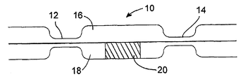
- FIG. 1 is a schematic representation of a Mach-Zehnder interferometer having two arms of equal length between the couplers and having an insert in one of the arms allowing control of thermal dependence of the MZI;
- FIG. 2 is a schematic representation of a Mach-Zehnder interferometer similar to that shown in FIG. 1 , but also having a taper in the insert of one of the arms used to fine tune the accuracy of thermal dependence of the MZI;
- FIG. 3 is a schematic representation of a Mach-Zehnder interferometer having equal arms and an insert of a different fiber in one of the arms, which insert extends beyond the couplers of the MZI;
- FIG. 4 is a schematic representation of a Mach-Zehnder interferometer having one arm longer than the other between the couplers, wherein the fibers of the two arms are dissimilar and their composition is chosen to provide control of thermal dependence of the MZI;
- FIG. 5 is a schematic representation of a Mach-Zehnder interferometer having one arm longer than the other between the couplers, wherein the fiber of the shorter arm has a segment of a different fiber composition to provide control of thermal dependence of the MZI;
- FIG. 6 is a schematic representation of a Mach-Zehnder interferometer having one arm longer than the other between the couplers, wherein the fiber of the longer arm has a segment of a different fiber composition to provide control of thermal dependence of the MZI;
- FIG. 7 is a schematic representation of a method used to achieve measurement and control of thermal dependence of a Mach-Zehnder interferometer in accordance with the present invention.
- FIG. 8 is a graph showing a characteristic sinusoidal transmission spectra at one of the output arms of a Mach-Zehnder device having different fibers as arms, at 5° C. and 55° C. respectively, without thermal compensation provided by the present invention
- FIG. 9 is a plot of wavelength values as a function of temperature for a Mach-Zehnder device without a compensating fiber and with a compensating fiber pursuant to the present invention.
- FIG. 10 is a plot of wavelength values as a function of temperature for a Mach-Zehnder device without a compensating taper in one of the arms, and with a compensating taper pursuant to the present invention.
- FIG. 1 illustrates a Mach-Zehnder interferometer 10 having two couplers 12 and 14 interconnected by two equal length arms 16 and 18 made of a standard SMF 28 fiber of index of refraction N 1 .
- fiber 18 has a segment 20 of length L 3 made of a different fiber, having a different index of refraction N 2 , which produces the desired thermo-optic effect. It is already known, for instance from U.S. Pat. Nos.
- the SMF-28 fiber of the first arm 16 has a fixed thermo-optic coefficient of about 8-10 ⁇ 6 /° C.
- the composition and length L 3 of the segment 20 of dissimilar fiber, which has been spliced in the fiber of the second arm 18 is so adjusted with dopants as to obtain simultaneously a similar thermo-optic coefficient dn/dT, but a different index of refraction than that of the arm 16 .
- a range of dopants, dopants such as GeO 2 , P 2 O 5 , B 2 O 3 , F, can be used for this purpose.
- GeO 2 in amounts of up to 40 wt % has the effect of increasing both the thermo-optic coefficient dn/dT and the index of refraction
- P 2 O 5 in amounts of up to 20 wt % has the effect of decreasing the thermo-optic coefficient dn/dT and of increasing the index of refraction
- B 2 O 3 in amounts of up to 7 wt % has the effect of decreasing both the thermo-optic coefficient dn/dT and the index of refraction.
- the MZI device thus designed is fixed on a substrate and suitably tensioned, with a unitary elongation ⁇ L/L preferably above 0.025%, or even above 0.05% to make it stable.
- the variation in length of the substrate in relation to temperature does not affect such design, since the lengths L 1 and L 2 being equal, will undergo exactly the same variations.
- the thermal wavelength drift of the MZI can thus be controlled within an accuracy of 1 to 2 pm/° C.
- FIG. 2 is a variant of that described with reference to FIG. 1 .
- this segment 22 is provided with an adiabatic taper 24 .
- the optical signal is not guided by the core of the fiber, but by the cladding, which has a dn/dT coefficient inferior to that of the core and the index of refraction smaller than that of the core. This provides a way of using such taper to better control the temperature dependence of the MZ device 10 , for example by fine-tuning the original setting of FIG. 1 .
- thermo-optic coefficient dn/dT is not too different, such as SMF-28 produced by Corning and INO 500 produced by Institut National d'Optique and Redfern GF2 produced by Redfern. In such cases, it suffices to determine the optimal taper length L 1 in order to obtain an overall dn/dT coefficient equal to that of the core of fiber SMF-28.
- the fiber of arm 16 is chosen as being SMF-28 and the fiber of insert 22 is chosen so as to have a thermo-optic coefficient dn/dT and the index of refraction N 2 superior to those of the SMF-28 fiber.
- INO 500 Ga—P/Si0 2
- Redfern GF2 Ga—B/Si0 2
- the insert 22 made of such doped fiber is tapered with a adiabatic taper 24 so that in this tapered region the optical signal is guided by the cladding of which the thermo-optic coefficient dn/dT is inferior to that of SM-28 fiber and of which the index of refraction is slightly inferior to that of the SMF-28 fiber.
- the length of the taper 24 is then adjusted so that the overall thermo-optic coefficient of the second arm 18 is equal to that of the first arm 16 and so that the index of refraction N 2 of the second arm 18 is superior to the index of refraction N 1 of the first arm 16 .
- the device is then mounted on the substrate as described with reference to the embodiment of FIG. 1 and shows similar temperature stability of the order of 1 to 2 pm/° C.
- thermo-optic coefficients of the two types of fibers are sufficiently close to ensure a maximum thermal dependence of the device of the order of 20 pm/° C. in the absence of the tapered region in the second arm.
- the embodiment shown in FIG. 3 is another variant of a Mach-Zehnder interferometer 10 having equal length arms 16 and 18 between the couplers 12 and 14 .
- the fiber of arm 16 is of the same composition as the input-output fiber 11 , for instance SMF-28, while the fiber of arm 16 is dissimilar and is provided with the required dopant to achieve the desired thermo-optic coefficient dn/dT to control the temperature dependence of the device 10 .
- the dissimilar arm 18 is part of a different fiber spliced into the input-output fiber 13 outside of the couplers 12 and 14 respectively.
- the couplers here are made with dissimilar fibers and are thus dissymmetric couplers.
- the Mach-Zehnder interferometer 10 has arms 26 and 28 of different lengths L 1 and L 2 , between the couplers 12 and 14 .
- the temperature-induced wavelength shift is determined by the thermo-optic effect and by the differential expansion between the two arms.
- the thermo-optic effect is dominant, expressed as: ( L 1 ⁇ ⁇ N 1 ⁇ T - L 2 ⁇ ⁇ N 2 ⁇ T )
- the difference in the geometrical length between the two arms 26 and 28 is not too large, typically in the range of about 1 mm for a spacing of 100 GHz, a small difference in dn/dT suffices to compensate for the thermal unbalance.
- the interferometer is then mounted on a substrate in the usual way, that is with two adhesive points on each side of the coupling region, said region being fixed by means of flexible gel.
- temperature dependence of the MZI device 10 is controlled within an accuracy of 0.2 to 1 pm/° C.
- this embodiment has the advantage of allowing more flexibility in the composition on the second arm.
- a variant of this embodiment consists in tapering a region of the fiber in one of the two arms to achieve the desired thermal dependence.
- FIG. 5 Still another variant of the embodiment shown in FIG. 4 , is illustrated in FIG. 5 .
- arm 26 is provided with an insert 30 of a different, doped composition, such as to cancel the thermo-optic effect and produce an MZI device 10 with controlled temperature dependence.
- FIG. 6 A further variant is illustrated in FIG. 6 , where the longer arm 28 , between couplers 12 and 14 , is provided with an insert 32 of a different, doped composition, such as to cancel the thermo-optic effect and provide an MZI device 10 with a controlled temperature dependence.
- FIG. 7 The method of testing the various designs of Mach-Zehnder interferometers described above and illustrated in FIGS. 1 to 6 is shown in FIG. 7 .
- the MZI device 10 of a given design is placed in a heating-cooling enclosure 34 where it can be heated and cooled within a predetermined range of temperatures, for example between ⁇ 35° C. and +85° C.
- a BBS broadband source 31 is used to launch a light signal into the MZI device 10 which is heated and cooled within the desired range of temperatures.
- the signals are processed by the MZI 10 and pass through switch 36 and into the OSA optical spectrum analyser 38 where the thermal dependence of the device 10 is measured within the predetermined range of temperatures generated in the enclosure 34 .
- the composition of the arms within the MZI can thus be adjusted by design to achieve the desired result.
- FIG. 8 An example of such measurement by OSA 38 of a characteristic sinusoidal transmission spectrum at one of the output arms of MZI 10 , is illustrated by the graph of FIG. 8 .
- This measurement is made at 5° C. and 55° C. respectively in an MZI having arms which are made of fibers of different lengths, without thermal compensation provided by the present invention.
- this graph there is a shift between the transmission peaks and minima at the different temperatures.
- the peaks and minima shift to lower wavelengths.
- FIG. 9 represents an actual plot of the temperature dependent shifts at temperatures between ⁇ 5° C. and +60° C. of two identically shaped MZI devices (crescent shape) with arms of different lengths and with one of the devices being provided with an insert for thermal compensation according to this invention.
- the MZI devices had about 50 GHz of wavelength spacing between channels.
- the first MZI device was fabricated entirely from SMF-fiber without any thermal compensation and the measurements of wavelength versus temperature are plotted with empty circles and a broken line in FIG. 9 .
- This MZI device has a thermal dependance of 8 pm/° C.
- the second MZI device was fabricated with an insert in the long arm as shown in FIG. 6 .
- the insert was 42 mm long and consisted of a doped fiber containing 12% by wt of P 2 O 5 in its core.
- the measurements of wavelength versus temperature of this device are plotted with black circles and a solid line in FIG. 9 and show a thermal dependence of only 0.5 pm/° C. It is clear from this plot that thermal compensation in accordance with the present invention produces significantly improved results.
- FIG. 10 represents another plot of two MZI devices in which the arms are of equal length and where the thermal compensation is improved by means of a taper as illustrated in FIG. 2 .
- the MZI device as illustrated in FIG. 1 having an insert of fiber INO-500, produced measurements shown in FIG. 10 by empty circles and a brocken line
- the improved MZI device as illustrated in FIG. 2 having an insert of fiber INO-500 and an adiabatic taper in the insert, produced measurements shown by black circles and a solid line in FIG. 10 . It is clear from this plot that the fine-tuning of the MZI device by means of an adiabatic taper produces improved thermal compensation.
Landscapes
- Physics & Mathematics (AREA)
- General Physics & Mathematics (AREA)
- Optics & Photonics (AREA)
- Instruments For Measurement Of Length By Optical Means (AREA)
- Optical Integrated Circuits (AREA)
Abstract
Description
where k0=2π/λ is the wave number, λ being the wavelength in vacuum; N1 and N2 are the effective indices of the optical fibers in the first and second arm respectively of the interferometer; L1 and L2 are the lengths of the first and second arm respectively of the interferometer; z1 and z2 are integration variables along the length of the first and second arm, respectively; and m is an integer.
where Δλ is the fringe spacing, i.e. the wavelength separation between two transmission peaks in one given output port of the interferometer; ε1 and ε2 are the unitary elongations of the arms 1 and 2, caused by thermal expansion of either the fiber or of the substrate.
where Ng1 and Ng2 are the group effective indices in the arms 1 and 2 respectively.
where L is the length of a small segment along the fiber.
It is still possible to choose other values for this difference so as to achieve a desired thermal dependence.
Claims (20)
Applications Claiming Priority (2)
| Application Number | Priority Date | Filing Date | Title |
|---|---|---|---|
| CA002335216A CA2335216C (en) | 2001-02-09 | 2001-02-09 | Passive thermal compensation of all-fiber mach-zehnder interferometer |
| PCT/CA2002/000148 WO2002065179A2 (en) | 2001-02-09 | 2002-02-08 | Passive thermal compensation of all-fiber mach-zehnder interferometer |
Publications (2)
| Publication Number | Publication Date |
|---|---|
| US20030152304A1 US20030152304A1 (en) | 2003-08-14 |
| US6850654B2 true US6850654B2 (en) | 2005-02-01 |
Family
ID=4168301
Family Applications (1)
| Application Number | Title | Priority Date | Filing Date |
|---|---|---|---|
| US10/258,913 Expired - Lifetime US6850654B2 (en) | 2001-02-09 | 2002-02-08 | Passive thermal compensation of all-fiber Mach-Zehnder interferometer |
Country Status (3)
| Country | Link |
|---|---|
| US (1) | US6850654B2 (en) |
| CA (1) | CA2335216C (en) |
| WO (1) | WO2002065179A2 (en) |
Cited By (2)
| Publication number | Priority date | Publication date | Assignee | Title |
|---|---|---|---|---|
| US20040257579A1 (en) * | 2003-06-18 | 2004-12-23 | Hitachi, Ltd. | Chemical sensor |
| US10534130B1 (en) * | 2019-05-21 | 2020-01-14 | Psiquantum, Corp. | Interferometer filters with compensation structure |
Families Citing this family (12)
| Publication number | Priority date | Publication date | Assignee | Title |
|---|---|---|---|---|
| US7305162B2 (en) * | 2002-05-30 | 2007-12-04 | Intel Corporation | Reducing the temperature sensitivity of optical waveguide interference filters |
| US7106449B2 (en) * | 2003-05-30 | 2006-09-12 | Agilent Technologies, Inc. | Systems and methods for fiber optic devices with reduced thermal sensitivity |
| CA2601836C (en) * | 2007-05-21 | 2017-02-28 | Adam Densmore | Silicon photonic wire waveguide biosensor |
| JP5399693B2 (en) * | 2008-07-14 | 2014-01-29 | 日本電信電話株式会社 | Optical wavelength multiplexing / demultiplexing circuit |
| SG188759A1 (en) * | 2011-09-21 | 2013-04-30 | Agency Science Tech & Res | Optical circuit for sensing a biological entity in a fluid and method of configuring the same |
| JP6699294B2 (en) * | 2016-03-30 | 2020-05-27 | 株式会社豊田中央研究所 | Optical filter and narrow linewidth wavelength light source |
| CN108844454A (en) * | 2018-06-25 | 2018-11-20 | 中国科学院上海光学精密机械研究所 | A kind of interferometer phase changer |
| FI129694B (en) | 2018-11-02 | 2022-06-30 | Teknologian Tutkimuskeskus Vtt Oy | Devices and methods for polarization splitting |
| US12196672B2 (en) | 2020-05-07 | 2025-01-14 | Hand Held Products, Inc. | Apparatuses, systems, and methods for sample testing |
| US12498328B2 (en) | 2020-05-07 | 2025-12-16 | Hand Held Products, Inc. | Apparatuses, systems, and methods for sample testing |
| US12553885B2 (en) | 2020-05-07 | 2026-02-17 | Hand Held Products, Inc. | Apparatuses, systems, and methods for sample testing |
| US11846574B2 (en) | 2020-10-29 | 2023-12-19 | Hand Held Products, Inc. | Apparatuses, systems, and methods for sample capture and extraction |
Citations (12)
| Publication number | Priority date | Publication date | Assignee | Title |
|---|---|---|---|---|
| US4725141A (en) | 1984-08-22 | 1988-02-16 | The General Electric Company, P.L.C. | Interferometers |
| US5295205A (en) | 1993-03-29 | 1994-03-15 | Corning Incorporated | Environmentally stable monolithic Mach-Zehnder device |
| US5636309A (en) | 1996-02-21 | 1997-06-03 | Lucent Technologies Inc. | Article comprising a planar optical waveguide mach-zehnder interferometer device, and method of making same |
| US5703975A (en) | 1995-06-09 | 1997-12-30 | Corning Incorporated | Interferometric switch |
| US5710848A (en) | 1994-05-16 | 1998-01-20 | Ecole Polytechnique De Montreal | Optimized non-linear effect tapered optical fiber and method of making same |
| EP0849231A1 (en) | 1996-12-20 | 1998-06-24 | Corning Incorporated | Athermalized codoped optical waveguide device |
| US5920666A (en) * | 1997-01-02 | 1999-07-06 | The Board Of Trustees For The Leland Stanford Junior University | Stable nonlinear Mach-Zehnder fiber switch |
| US5943458A (en) | 1995-06-09 | 1999-08-24 | Corning Incorporated | Mach-Zehnder interferometric devices with composite fibers |
| US6031948A (en) | 1998-03-03 | 2000-02-29 | Applied Fiber Optics, Inc. | Fused-fiber multi-window wavelength division multiplexer using an unbalanced Mach-Zehnder interferometer and method of making same |
| EP0982607A1 (en) | 1998-08-27 | 2000-03-01 | Corning Incorporated | Athermal integrated optical waveguide device |
| US6118909A (en) | 1997-10-01 | 2000-09-12 | Lucent Technologies Inc. | Athermal optical devices |
| EP1065539A2 (en) | 1999-06-23 | 2001-01-03 | Thomas & Betts International, Inc. | Optical fiber mach-zehnder interferometer employing miniature bends |
-
2001
- 2001-02-09 CA CA002335216A patent/CA2335216C/en not_active Expired - Lifetime
-
2002
- 2002-02-08 WO PCT/CA2002/000148 patent/WO2002065179A2/en not_active Ceased
- 2002-02-08 US US10/258,913 patent/US6850654B2/en not_active Expired - Lifetime
Patent Citations (13)
| Publication number | Priority date | Publication date | Assignee | Title |
|---|---|---|---|---|
| US4725141A (en) | 1984-08-22 | 1988-02-16 | The General Electric Company, P.L.C. | Interferometers |
| US5295205A (en) | 1993-03-29 | 1994-03-15 | Corning Incorporated | Environmentally stable monolithic Mach-Zehnder device |
| US5710848A (en) | 1994-05-16 | 1998-01-20 | Ecole Polytechnique De Montreal | Optimized non-linear effect tapered optical fiber and method of making same |
| US5703975A (en) | 1995-06-09 | 1997-12-30 | Corning Incorporated | Interferometric switch |
| US5943458A (en) | 1995-06-09 | 1999-08-24 | Corning Incorporated | Mach-Zehnder interferometric devices with composite fibers |
| US5636309A (en) | 1996-02-21 | 1997-06-03 | Lucent Technologies Inc. | Article comprising a planar optical waveguide mach-zehnder interferometer device, and method of making same |
| US6201918B1 (en) * | 1996-12-20 | 2001-03-13 | Corning Incorporated | Athermalized codoped optical waveguide device |
| EP0849231A1 (en) | 1996-12-20 | 1998-06-24 | Corning Incorporated | Athermalized codoped optical waveguide device |
| US5920666A (en) * | 1997-01-02 | 1999-07-06 | The Board Of Trustees For The Leland Stanford Junior University | Stable nonlinear Mach-Zehnder fiber switch |
| US6118909A (en) | 1997-10-01 | 2000-09-12 | Lucent Technologies Inc. | Athermal optical devices |
| US6031948A (en) | 1998-03-03 | 2000-02-29 | Applied Fiber Optics, Inc. | Fused-fiber multi-window wavelength division multiplexer using an unbalanced Mach-Zehnder interferometer and method of making same |
| EP0982607A1 (en) | 1998-08-27 | 2000-03-01 | Corning Incorporated | Athermal integrated optical waveguide device |
| EP1065539A2 (en) | 1999-06-23 | 2001-01-03 | Thomas & Betts International, Inc. | Optical fiber mach-zehnder interferometer employing miniature bends |
Non-Patent Citations (2)
| Title |
|---|
| Bilodeau et al.; Ultraviolet-light photosensitivity in . . . ; Oct. 15, 1990; pp. 1138-1140; Optics Letters / vol. 15, No. 20. |
| Malo et al.; Unbalanced Dissimilar-Fibre Mach-Zehnder Interferometer; Oct. 12, 1989; pp. 1416-1417; Electronics Letters / vol. 25, No. 21. |
Cited By (5)
| Publication number | Priority date | Publication date | Assignee | Title |
|---|---|---|---|---|
| US20040257579A1 (en) * | 2003-06-18 | 2004-12-23 | Hitachi, Ltd. | Chemical sensor |
| US10534130B1 (en) * | 2019-05-21 | 2020-01-14 | Psiquantum, Corp. | Interferometer filters with compensation structure |
| US11048041B2 (en) | 2019-05-21 | 2021-06-29 | Psiquantum, Corp. | Interferometer filters with compensation structure |
| US11543587B2 (en) | 2019-05-21 | 2023-01-03 | Psiquantum, Corp. | Interferometer filters with compensation structure |
| US11874496B2 (en) | 2019-05-21 | 2024-01-16 | Psiquantum, Corp. | Interferometer filters with compensation structure |
Also Published As
| Publication number | Publication date |
|---|---|
| CA2335216A1 (en) | 2002-08-09 |
| CA2335216C (en) | 2007-06-05 |
| US20030152304A1 (en) | 2003-08-14 |
| WO2002065179A2 (en) | 2002-08-22 |
Similar Documents
| Publication | Publication Date | Title |
|---|---|---|
| US6850654B2 (en) | Passive thermal compensation of all-fiber Mach-Zehnder interferometer | |
| EP0791842B1 (en) | Article comprising a planar optical waveguide mach-zehnder interferometer device, and method of making same | |
| US5042898A (en) | Incorporated Bragg filter temperature compensated optical waveguide device | |
| US20030053783A1 (en) | Optical fiber having temperature independent optical characteristics | |
| JP4585091B2 (en) | Waveguide grating device | |
| US6031948A (en) | Fused-fiber multi-window wavelength division multiplexer using an unbalanced Mach-Zehnder interferometer and method of making same | |
| Kokubun et al. | Temperature-independent narrow-band optical filter by an athermal waveguide | |
| US6327405B1 (en) | Devices and methods for temperature stabilization of Bragg grating structures | |
| US9341770B2 (en) | Thermal compensation composition of optical fiber connector containing a fiber Bragg grating | |
| US7164478B2 (en) | Apparatus and methods for stabilization and control of fiber devices and fiber devices including the same | |
| US6900898B2 (en) | Temperature insensitive Mach-Zehnder interferometers and devices | |
| EP0629886A1 (en) | Passive temperature-insensitive fabry-perot etalons | |
| US6263128B1 (en) | Fiber unbalanced Mach-Zehnder interferometers with flat-top spectral response for application in wavelength division multiplexers | |
| US6324322B1 (en) | Fused-fiber multi-window wavelength filter using unbalanced Michelson Interferometer | |
| US7177511B2 (en) | Optical fiber, optical fiber filter, and optical amplifier | |
| US7106449B2 (en) | Systems and methods for fiber optic devices with reduced thermal sensitivity | |
| Hibino et al. | Temperature-insensitive UV-induced Bragg gratings in silica-based planar lightwave circuits on Si | |
| US6888981B2 (en) | Wavelength division multiplexing coupler with loss element | |
| Tabti et al. | Polarization insensitive Bragg gratings in Si3N4 waveguides | |
| KR102191682B1 (en) | Sagnac interferometer having the nearly zero temperature sensitivity made by different birefringent optical fibers | |
| JPS6316204A (en) | Mach-zehnder optical interferometer | |
| CA2354752A1 (en) | Temperature insensitive mach-zehnder interferometers and devices | |
| KR20050040522A (en) | Thermal stability and manufacture of all fiber type interleaver | |
| KR20070056562A (en) | Optical time delay interferometer with phase variable function | |
| KR20240074612A (en) | Optical delay and optical interferometer with suppressed temperature dependence using polarization-maintaining optical fiber |
Legal Events
| Date | Code | Title | Description |
|---|---|---|---|
| AS | Assignment |
Owner name: ITF TECHNOLOGIES OPTIQUES INC., CANADA Free format text: ASSIGNMENT OF ASSIGNORS INTEREST;ASSIGNORS:GONTHIER, FRANCOIS;GODBOUT, NICOLAS;SEGUIN, FRANCOIS;AND OTHERS;REEL/FRAME:016104/0152 Effective date: 20021009 |
|
| STCF | Information on status: patent grant |
Free format text: PATENTED CASE |
|
| AS | Assignment |
Owner name: AVENSYS LABORATORIES INC., CANADA Free format text: ASSIGNMENT OF ASSIGNORS INTEREST;ASSIGNOR:ITF OPTICAL TECHNOLOGIES INC.;REEL/FRAME:017794/0673 Effective date: 20060413 Owner name: ITF LABORATORIES INC./LABORATOIRES ITF INC., CANAD Free format text: CHANGE OF NAME;ASSIGNOR:AVENSYS LABORATORIES INC.;REEL/FRAME:017794/0683 Effective date: 20060509 |
|
| FPAY | Fee payment |
Year of fee payment: 4 |
|
| SULP | Surcharge for late payment | ||
| FPAY | Fee payment |
Year of fee payment: 8 |
|
| AS | Assignment |
Owner name: ITF TECHNOLOGIES INC., QUEBEC Free format text: LIQUIDATION AGREEMENT;ASSIGNOR:ITF LABORATORIES INC.;REEL/FRAME:036806/0568 Effective date: 20150731 |
|
| FPAY | Fee payment |
Year of fee payment: 12 |