US6837588B2 - Spread illuminating apparatus with means for reflecting light dispersely - Google Patents
Spread illuminating apparatus with means for reflecting light dispersely Download PDFInfo
- Publication number
- US6837588B2 US6837588B2 US10/321,655 US32165502A US6837588B2 US 6837588 B2 US6837588 B2 US 6837588B2 US 32165502 A US32165502 A US 32165502A US 6837588 B2 US6837588 B2 US 6837588B2
- Authority
- US
- United States
- Prior art keywords
- light
- reflection pattern
- conductive plate
- illuminating apparatus
- dispersive
- Prior art date
- Legal status (The legal status is an assumption and is not a legal conclusion. Google has not performed a legal analysis and makes no representation as to the accuracy of the status listed.)
- Expired - Fee Related
Links
- 239000000463 material Substances 0.000 claims abstract description 9
- 239000004973 liquid crystal related substance Substances 0.000 description 6
- 239000011248 coating agent Substances 0.000 description 4
- 238000000576 coating method Methods 0.000 description 4
- 230000000694 effects Effects 0.000 description 4
- 238000006243 chemical reaction Methods 0.000 description 3
- 210000002858 crystal cell Anatomy 0.000 description 3
- 230000003287 optical effect Effects 0.000 description 3
- 230000001413 cellular effect Effects 0.000 description 2
- 238000010276 construction Methods 0.000 description 2
- 230000002411 adverse Effects 0.000 description 1
- 210000004027 cell Anatomy 0.000 description 1
- 230000001627 detrimental effect Effects 0.000 description 1
- 230000002708 enhancing effect Effects 0.000 description 1
- 238000004519 manufacturing process Methods 0.000 description 1
- 238000012986 modification Methods 0.000 description 1
- 230000004048 modification Effects 0.000 description 1
- 238000009877 rendering Methods 0.000 description 1
Images


Classifications
-
- G—PHYSICS
- G02—OPTICS
- G02B—OPTICAL ELEMENTS, SYSTEMS OR APPARATUS
- G02B6/00—Light guides; Structural details of arrangements comprising light guides and other optical elements, e.g. couplings
- G02B6/0001—Light guides; Structural details of arrangements comprising light guides and other optical elements, e.g. couplings specially adapted for lighting devices or systems
- G02B6/0011—Light guides; Structural details of arrangements comprising light guides and other optical elements, e.g. couplings specially adapted for lighting devices or systems the light guides being planar or of plate-like form
- G02B6/0013—Means for improving the coupling-in of light from the light source into the light guide
- G02B6/0023—Means for improving the coupling-in of light from the light source into the light guide provided by one optical element, or plurality thereof, placed between the light guide and the light source, or around the light source
- G02B6/0028—Light guide, e.g. taper
-
- G—PHYSICS
- G02—OPTICS
- G02B—OPTICAL ELEMENTS, SYSTEMS OR APPARATUS
- G02B6/00—Light guides; Structural details of arrangements comprising light guides and other optical elements, e.g. couplings
- G02B6/0001—Light guides; Structural details of arrangements comprising light guides and other optical elements, e.g. couplings specially adapted for lighting devices or systems
- G02B6/0011—Light guides; Structural details of arrangements comprising light guides and other optical elements, e.g. couplings specially adapted for lighting devices or systems the light guides being planar or of plate-like form
- G02B6/0033—Means for improving the coupling-out of light from the light guide
- G02B6/0035—Means for improving the coupling-out of light from the light guide provided on the surface of the light guide or in the bulk of it
- G02B6/0038—Linear indentations or grooves, e.g. arc-shaped grooves or meandering grooves, extending over the full length or width of the light guide
-
- G—PHYSICS
- G02—OPTICS
- G02B—OPTICAL ELEMENTS, SYSTEMS OR APPARATUS
- G02B6/00—Light guides; Structural details of arrangements comprising light guides and other optical elements, e.g. couplings
- G02B6/0001—Light guides; Structural details of arrangements comprising light guides and other optical elements, e.g. couplings specially adapted for lighting devices or systems
- G02B6/0011—Light guides; Structural details of arrangements comprising light guides and other optical elements, e.g. couplings specially adapted for lighting devices or systems the light guides being planar or of plate-like form
- G02B6/0066—Light guides; Structural details of arrangements comprising light guides and other optical elements, e.g. couplings specially adapted for lighting devices or systems the light guides being planar or of plate-like form characterised by the light source being coupled to the light guide
- G02B6/0068—Arrangements of plural sources, e.g. multi-colour light sources
Definitions
- the present invention relates to a spread illuminating apparatus, and more particularly to a spread illuminating apparatus used with a liquid crystal display.
- a liquid crystal display (hereinafter referred to as LCD), which is small in power consumption, low in profile, and light in weight, is heavily used in electric products such as a personal computer (hereinafter referred to as PC), a cellular phone, and the like, and is increasingly demanded.
- PC personal computer
- PC personal computer
- the LCD Since a liquid crystal of the LCD does not emit light by itself, the LCD requires an illuminating means to radiate light on the liquid crystal when used in a place where sunlight or interior lighting is not fully available.
- a PC particularly notebook-type PC, and a cellular phone are required to be lower in profile and smaller in power consumption, and the requirements are fulfilled by a spread illuminating apparatus of side light type.
- a spread illuminating apparatus 1 ′ generally comprises a light conductive plate 2 made of a light transmissible material, and a bar-like lamp 5 disposed along and close to an end face 8 of the light conductive plate 2 .
- Light emitted from the light lamp 5 is introduced into the light conductive plate 2 and directed to an LCD (not shown) disposed under the light conductive plate 2 .
- the lamp 5 comprises a light conductive bar 3 made of a light transmissible material, and two spot-like light sources 4 , 4 (for example, light emitting diodes) disposed facing respective end faces 6 , 7 of the light conductive bar 3 .
- the light conductive bar 3 has an optical path conversion means 12 formed on a side face thereof opposite to a side face 9 facing the end face 8 of the light conductive plate 2 .
- the optical path conversion means 12 comprises, for example, a plurality of grooves shaped triangular in section, and is adapted to guide light, which is emitted from the light source 4 into the light conductive bar 3 , toward the end face 8 of the light conductive plate 2 in a substantially uniform manner.
- the light conductive bar 3 is disposed with its side face 9 facing the end face 8 of the light conductive plate 2 with a predetermined distance therebetween.
- the light conductive bar 3 has a light reflection member (frame) 13 substantially U shaped in section and disposed therearound.
- the light reflection member 13 covers the longitudinal faces of the light conductive bar 3 except the side face 9 facing the light conductive plate 2 .
- the light conductive plate 2 has a light reflection pattern 19 formed on its upper face 15 , and has a plain surface on its lower face 26 .
- the light reflection pattern 19 has a stair-like configuration in section, comprising a plurality of small surfaces 17 having its longitudinal direction parallel to the length of the light conductive bar 3 , and a plurality of large surfaces 18 each present between two adjacent small surfaces 17 .
- the light reflection pattern 19 is adapted to guide light, which is emitted from the lamp 5 into the light conductive plate 2 , toward the LCD (not shown) disposed under the light conductive plate 2 .
- the light reflection pattern 19 may alternatively comprise a plurality of grooves, and a plurality of flat portions present between two adjacent grooves.
- an interference fringe appears, which is formed by the striping generated due to a difference in light outgoing efficiency resulting from a difference in refractive index between at the small surface 17 and at the large surface 18 , and by the arrangement of the mosaic pattern (cell boundary) of crystal cells constituting pixels of the LCD, and which is detrimental to the observation of the image on the display.
- the moire pattern is closely related with the configuration of the light reflection pattern 19 , specifically, the dimensions and inclinations of the small surfaces 17 and the large surfaces 18 , or the like.
- the light and dark striping is peculiar to the front-lighting system, and is characterized in that its location and striping interval change according to the position of the observer's eye. It has become apparent that the light and dark striping is generated by reflected light due to Fresnel reflection at the lower face of the light conductive plate opposite to the face provided with the light reflection pattern, that is, reflected light caused by the difference in refractive index between the light conductive plate and the air. It has been known that this reflected light has an adverse influence on the contrast characteristics of the display device, and the light conductive plate normally has non-reflective coating applied to its lower face for improving contrast.
- the current non-reflective coating suppresses light reflection significantly but not down to 0% across the visible display area, normally allowing some 0.2% of light incident thereon to be reflected. This slight amount of reflected light generates the light and dark striping.
- the present invention has been made in view of the above problems, and it is an object of the present invention to provide a spread illuminating apparatus, in which the light and dark striping of a kind different from the moire pattern is suppressed without increasing the number of components and also without detriment to the usability of light.
- a spread illuminating apparatus comprises: a light conductive plate made of a light transmissible material; a bar-like lamp disposed along and close to an end face of the light conductive plate; a light reflection pattern having a stair-like configuration in section, and formed on a major face of the light conductive plate; and a light dispersive-reflection pattern formed on a major face of the light conductive plate opposite to the major face provided with the light reflection pattern.
- the light dispersive-reflection pattern comprises a plurality of convex surfaces arrayed continuous with one another in parallel.
- the light dispersive-reflection pattern comprises a plurality of convex surfaces arrayed in parallel to one another, and a plurality of flat portions each present between two adjacent convex surfaces.
- a maximum angle made by a tangent line to the convex surface with respect to an imaginary datum parallel to the light conductive plate does not exceed 3 degrees.
- the light dispersive-reflection pattern comprises a plurality of concave surfaces arrayed continuously with one another in parallel.
- the light dispersive-reflection pattern comprises a plurality of concave surfaces arrayed in parallel to one another, and a plurality of flat portions each present between two adjacent concave surfaces.
- a maximum angle made by a tangent line to the concave surface with respect to an imaginary datum parallel to the light conductive plate does not exceed 3 degrees.
- the light dispersive-reflection pattern comprises a plurality of polygonal surfaces each composed of a plurality of flat surfaces, and arrayed continuously with one another in parallel, and an angle made by each of the flat surfaces with respect to an imaginary datum parallel to the light conductive plate varies stepwise and gradually.
- the light dispersive-reflection pattern comprises a plurality of polygonal surfaces each composed of a plurality of flat surfaces, and arrayed in parallel to one another, and a plurality of flat portions each present between two adjacent polygonal surfaces, and an angle made by each the flat surfaces with respect to an imaginary datum parallel to the light conductive plate varies stepwise and gradually.
- a maximum angle of the angles made by the flat surfaces with respect to the imaginary datum does not exceed 3 degrees.
- the light dispersive-reflection pattern is oriented at a predetermined angle with respect to the light reflection pattern.
- the predetermine angle ranges from 10 to 35 degrees.
- the 0.2% light rays, which are incident on the lower face of the light conductive plate but fail to exit out from there while the remaining incident light rays exit out, and which are conventionally reflected at the lower face of the light conductive plate in the uniform direction back toward the light reflection pattern, are now reflected back in random directions by means of the light dispersive-reflection pattern formed on the lower face of the light conductive plate, consequently making the light rays exit out the light conductive plate through the light reflection pattern in random directions, whereby it does not happen that the angle ranges of “no light coming from the light reflection pattern” are aligned to one another, and therefore the light and dark striping is not recognizable.
- the same effect can be realized without detriment to other display performance when the pattern is configured such that the maximum angle made by the tangent line to the convex, concave or polygonal surface with respect the datum parallel to the light conductive plate is 3 degrees or smaller
- the light dispersive-reflection pattern is formed directly on the light conductive plate without using any additional materials or components, thereby holding down cost increase.
- the moire pattern is effectively suppressed.
- FIG. 1 is a perspective view of a spread illuminating apparatus according to a first embodiment of the present invention
- FIG. 2 is an explanatory view of travel paths of light rays, showing how a light and dark striping is caused in a conventional apparatus;
- FIG. 3 is an explanatory view of angle ranges of exiting direction of the light rays of FIG. 2 ;
- FIG. 4 is a partial cross-sectional view of a light conductive plate of FIG. 1 ;
- FIG. 5 is a partial cross-sectional view, for comparison purpose, of a light conductive plate of a conventional apparatus
- FIG. 6 is a partial cross-sectional view of a light dispersive-reflection pattern according to the first embodiment of the present invention.
- FIG. 7 is an enlarged view of the part B of FIG. 6 ;
- FIG. 8 is a partial cross-sectional view of a light conductive plate according to a second embodiment of the present invention.
- FIG. 9 is a partial cross-sectional view of a light conductive plate according to a third embodiment of the present invention.
- FIG. 10 is a partial cross-sectional view of a light conductive plate according to a fourth embodiment of the present invention.
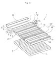
- FIG. 11 is an exploded perspective view of a spread illuminating apparatus of the present invention, showing a light conductive plate including a light reflection pattern and a light dispersive-reflection pattern according to a fifth embodiment;
- FIG. 12 is an exploded perspective view of a spread illuminating apparatus of the present invention, showing a light conductive plate including a light reflection pattern and a light dispersive-reflection pattern according to a sixth embodiment.
- FIG. 13 is an exploded perspective view of a conventional spread illuminating apparatus.
- the spread illuminating apparatus of the present invention is characterized by forming, on the lower face of a light conductive plate of a conventional spread illuminating apparatus, a light dispersive-reflection pattern which is adapted to reflect light in random directions toward a light reflection pattern, and in the construction drawings of the respective embodiments the construction elements corresponding to the elements of the prior art shown in FIG. 13 have the same reference numbers and will not be described in detail.
- a spread illuminating apparatus 1 generally comprises: a light conductive plate 2 ; a bar-like lamp 5 disposed along and close to an end face 8 of the light conductive plate 2 ; and a light reflection member (frame) 13 .
- the light conductive plate 2 has a light reflection pattern 19 formed on its upper face (observation surface) 15 .
- the light reflection pattern 19 is adapted to guide light, which is introduced into the light conductive plate 2 through the end face 8 , toward an LCD L disposed under a lower face 16 of the light conductive plate 2 in a uniform manner regardless of the distance from the lamp 5 .
- the lamp 5 comprises: a light conductive bar 3 made of a light transmissible material, and having an optical path conversion means 12 on one side face thereof, and spot-like light sources 4 , 4 disposed respectively on both end faces 6 , 7 of the light conductive bar 3 .
- the light reflection member 13 is substantially U-shaped in section and is set so as to enclose the light conductive bar 3 .
- the light reflection pattern 19 has a stair-like configuration in section, comprising: a plurality of small surfaces 17 having its longitudinal direction oriented in parallel to or at a predetermined angle with the length of the light conductive bar 3 ( FIG. 1 shows a parallel orientation); and a plurality of large surfaces 18 each present between two adjacent small surfaces 17 .
- the light conductive plate 2 has a light dispersive-reflection pattern 21 formed on its lower face 16 , and the surface of the light dispersive-reflection pattern 21 is provided with a non-reflective coating (not shown).
- the light dispersive-reflection pattern 21 like the light reflection pattern 19 formed on the upper face 15 of the light conductive plate 2 , is oriented in parallel to or at a predetermined angle with (an embodiment of orientation “at a predetermined angle” will be described herein later) the length of the light conductive bar 3 .
- Light rays which account for some 0.2% of entire light rays incident on the lower face 16 of the light conductive plate 2 , namely on the light dispersive-reflection pattern 21 , and which, despite of the non-reflective coating, fail to exit out the light conductive plate 2 as above described, are reflected in random directions toward the light reflection pattern 19 thus exiting out from the light reflection pattern 19 also in random directions, thereby suppressing the generation of the light and dark striping which appears according to the position of the observer's eye (this is to be described in detail later).
- the light reflection pattern 19 has a stair-like configuration in section, comprising small surfaces and large surfaces, but is not limited to the configuration and may alternatively comprise grooves shaped triangular in section and flat portions present between two adjacent grooves, or may comprise grooves shaped trapezoidal in section, grooves with multiple steps, or grooves with a curved outline.
- the lamp 5 has two light sources 4 , 4 disposed respectively on the both end faces 6 , 7 of the light conductive bar 3 , but is not limited to the configuration and may alternatively have one light source 4 disposed only one of the end faces 6 , 7 .
- the lamp 5 may be a fluorescent tube instead of a combination of the light conductive bar 3 and the light source(s) 4 .
- the light conductive plate 2 has one lamp 5 disposed along and close to the one end face 8 but is not limited to the configuration and may alternatively have two lamps 5 disposed along and close to the end faces 8 , 10 , respectively.
- the light and dark striping above described is attributable to the configuration of the light reflection pattern and to the undesired light reflected at the lower face of the light conductive plate, and is considered to be generated by the following mechanism.
- the mechanism will be described with reference to FIGS. 2 and 3 by way of the light conductive plate 2 of the conventional spread illuminating apparatus 1 ′ shown in FIG. 13 .
- the term “light ray(s)” used in the description and illustrated in FIGS. 2 to 5 is referred to the above mentioned 0.2% light rays out of the entire light rays that are reflected at the light reflection pattern 19 and progress toward the lower face 16 or 26 of the light conductive plate 2 , assuming that the 0.2% light rays are reflected at the lower surfaces 12 or 26 back toward the light reflection pattern 19 with the remaining light rays passing through the lower face 16 or 26 to exit out the light conductive plate 2 .
- the light reflection pattern 19 includes a plurality of small surfaces 17 (though only one is shown in FIGS. 2 and 3 ), so when the light reflection pattern 19 has the small surfaces formed at regular intervals, a plurality of angle ranges D are generated and there appear a plurality of dark areas.
- the arrows indicate travel paths of light rays, which are reflected at the small surfaces 17 of the light reflection pattern 19 formed on the upper face 15 of the light conductive plate 2 toward the light dispersive-reflection pattern 21 formed on the lower face 16 of the light conductive plate 2 , reflected at the light dispersive-reflection pattern 21 toward the light reflection pattern 19 , refracted by the surfaces of the light reflection pattern 19 , and exit out the light conductive plate 2 .
- the arrows indicate travel paths of light rays in the conventional light conductive plate 2 having a plain surface on the lower face 26 .
- an observer's eye 35 is shown to be positioned near the light conductive plate 2 , but actually is positioned far therefrom. So, an observer recognizes respective arrows as having a uniformly aligned outgoing angle at a given area of the light reflection pattern. Light rays emitted from the lamp 5 into the light conductive plate 2 are reflected at various portions thereof including the small surfaces 17 and the large surfaces 18 of the light reflection pattern 19 , but only light rays 41 reflected at the small surfaces 17 in the same direction are indicated.
- the light rays 41 are reflected at the plain surface of the lower face 26 to turn into light rays 42 which all progress in the same direction.
- the light rays 42 are refracted by the small surfaces 17 to turn into light rays 43 which all exit out the light conductive plate 2 in the same direction.
- the observer's eye 35 is at a place positioned in the direction indicted by an arrow 44 , one particular light ray 43 exiting out in the direction not parallel to the arrow 44 does not progress to the observer's eye 35 , which means that the observer's eye 35 is in “the angle range D of no light from the light reflection pattern” shown in FIG. 3 , and which makes the observer recognize the portion as a dark area of a striping.
- light rays 31 a , 31 b and 31 c are dispersively reflected at the light dispersive-reflection pattern 21 formed on the lower face 16 of the light conductive plate 2 thereby turning into light rays 32 a , 32 b and 32 c , respectively, which progress in their respective different directions.
- the light rays 32 a , 32 b and 32 c are refracted by the surfaces of the light reflection pattern 19 and exit out the light conductive plate 2 in their different directions.
- only one light ray 33 originating from the light ray 32 b and exiting out so as to overlap the arrow 34 is shown.
- the light dispersive-reflection pattern 21 faces the LCD L, comprises a plurality of surfaces each shaped convex in section, having its longitudinal direction in parallel to the length of the light conductive bar 3 , and continuously arrayed in a direction normal to the length of the light conductive bar 3 forming a valley between two adjacent surfaces, and thus is oriented parallel to the light reflection pattern 19 .
- the light dispersive-reflection pattern 21 will be further described with reference to FIG. 6 , which is exaggerated for ease of understanding.
- the degree of the convexity specifically, the distance from the apex of the convex surface to the bottom level of the valley formed between two adjacent convex surfaces is preferably determined such that a maximum angle ⁇ max, which is defined by a tangent line S with respect to an imaginary datum T parallel to the light conductive plate 2 , is 3 degrees or smaller.
- the light dispersive-reflection pattern 21 comprising the convex surfaces, on which an angle ⁇ i defined by a tangent line with respect to the datum T varies continuously
- the light rays 31 a , 31 b and 31 c reflected at respective small surfaces 17 in the same direction are reflected back toward the light reflection pattern 19 to turn respectively into light rays 32 a , 32 b and 32 c to progress in respective different directions.
- the light rays which are reflected at respective small surfaces 17 of the light reflection pattern 19 toward the lower face of the light conductive plate 2 , and which then, in case of the light conductive plate 2 (shown in FIG.
- the pitch P of the light dispersive-reflection pattern 21 indicated in FIG. 4 is desirably set to differ from that of the light reflection pattern 19 , which is more effective in suppressing the light and dark striping.
- a bottom 51 of the valley between two adjacent convex surfaces of the light dispersive-reflection pattern 21 is rounded so that the light dispersive-reflection pattern 21 is less noticeable when viewed from the observing side thereby enhancing the level of visibility.
- the light dispersive-reflection pattern does not have to be configured as shown in FIG. 6 , but may alternatively be configured as shown in FIGS. 8 to 10 (these figures are exaggerated for ease of understanding).
- a light dispersive-reflection pattern 21 ′ comprises a plurality of surfaces each shaped concave in section and continuously arrayed, and is oriented parallel to the light reflection pattern 19 .
- the angle ⁇ i defined by a tangent line with respect to the datum T varies continuously as in the light dispersive-reflection pattern 21 (see FIG. 6 ), and therefore has the same effect.
- a light dispersive-reflection pattern 21 ′′ comprises a plurality of polygonal surfaces each comprised of a plurality of flat surfaces ( 61 to 67 in this embodiment) and continuous with one another via a flat portion 68 substantially parallel to the datum T.
- an angle defined by a tangent line with respect to the datum T varies gradually, though not continuously as in the preceding embodiments, rendering angles ⁇ A, ⁇ B and ⁇ C in a stepwise manner, and the same effect can be achieved as in the light dispersive-reflection pattern 21 shown in FIG. 4 .
- the maximum angle ⁇ A is preferably set to be 3 degrees or smaller.
- the flat portion 68 may be eliminated.
- a light dispersive-reflection pattern 21 ′′′ comprises a plurality of convex surfaces continuous with one another via a flat portion 71 .
- the light dispersive-reflection pattern 21 ′′′ has the same structure as the light dispersive-reflection pattern 21 except for the flat portion 71 present between two adjacent convex surfaces, and has the same effect with an advantage that the presence of the flat portion 71 eases the production of the pattern.
- the same advantage can be achieved also if the light dispersive-reflection pattern 21 ′ shown in FIG. 8 is provided with a flat portion between two adjacent concave surfaces.
- FIG. 11 shows an illuminating apparatus of the present invention, in which the moire pattern is suppressed as well as the light and dark striping.
- the difference from the embodiment shown in FIG. 4 is that the light reflection pattern 19 ′ formed on the upper face 15 of the light conductive plate 2 is structured such that the small surfaces 17 ′ are positioned at random intervals instead of regular intervals, that is, the large surfaces 18 ′ are randomly dimensioned.
- the pattern may be oriented parallel to the length of the light conductive bar 3 , or may alternatively be oriented at a predetermined angle therewith.
- the light dispersive-reflection pattern is not limited to the configuration shown in FIG. 4 but may alternatively be configured as shown in FIGS. 8 to 10 .
- the light reflection pattern may alternatively comprise grooves and flat portions, wherein the grooves are positioned at random intervals, or may be otherwise configured as conventionally available as long as it is patterned at random intervals.
- FIG. 12 shows another spread illuminating apparatus of the present invention, in which the moire pattern is suppressed as well as the light and dark striping as in the embodiment shown in FIG. 11 .
- the difference from the embodiment shown in FIG. 4 is that the light reflection pattern 19 and the light dispersive-reflection pattern 21 are formed so as to be oriented at a predetermined angle ⁇ with respect to each other.
- the light dispersive-reflection pattern is not limited to the configuration shown in FIG. 4 but may alternatively be configured as shown in FIGS. 8 to 10 .
- the light reflection pattern may alternatively comprise grooves and flat portions, wherein the grooves are positioned at random intervals, or may be otherwise configured as conventionally available.
Landscapes
- Physics & Mathematics (AREA)
- General Physics & Mathematics (AREA)
- Optics & Photonics (AREA)
- Planar Illumination Modules (AREA)
Abstract
A spread illuminating apparatus having a light conductive plate made of a light transmissible material and a bar-like lamp disposed along and close to an end face of the light conductive plate. The spread illuminating apparatus also having a light reflection pattern having a stair-like configuration from a cross-sectional perspective. The light reflection pattern is formed on a major face of the light conductive plate. The spread illuminating apparatus also has a light dispersive-reflection pattern which has, for example, a plurality of convex surfaces which are formed on a major face of the light conductive plate opposite to the major face of the light conductive plate, which is provided with the light reflection pattern.
Description
1. Field of the Invention
The present invention relates to a spread illuminating apparatus, and more particularly to a spread illuminating apparatus used with a liquid crystal display.
2. Description of the Related Art
A liquid crystal display (hereinafter referred to as LCD), which is small in power consumption, low in profile, and light in weight, is heavily used in electric products such as a personal computer (hereinafter referred to as PC), a cellular phone, and the like, and is increasingly demanded.
Since a liquid crystal of the LCD does not emit light by itself, the LCD requires an illuminating means to radiate light on the liquid crystal when used in a place where sunlight or interior lighting is not fully available.
A PC, particularly notebook-type PC, and a cellular phone are required to be lower in profile and smaller in power consumption, and the requirements are fulfilled by a spread illuminating apparatus of side light type.
A conventional spread illuminating apparatus of side light type is shown in FIG. 13. In FIG. 13 , a spread illuminating apparatus 1′ generally comprises a light conductive plate 2 made of a light transmissible material, and a bar-like lamp 5 disposed along and close to an end face 8 of the light conductive plate 2. Light emitted from the light lamp 5 is introduced into the light conductive plate 2 and directed to an LCD (not shown) disposed under the light conductive plate 2.
The lamp 5 comprises a light conductive bar 3 made of a light transmissible material, and two spot-like light sources 4, 4 (for example, light emitting diodes) disposed facing respective end faces 6, 7 of the light conductive bar 3. The light conductive bar 3 has an optical path conversion means 12 formed on a side face thereof opposite to a side face 9 facing the end face 8 of the light conductive plate 2. The optical path conversion means 12 comprises, for example, a plurality of grooves shaped triangular in section, and is adapted to guide light, which is emitted from the light source 4 into the light conductive bar 3, toward the end face 8 of the light conductive plate 2 in a substantially uniform manner. The light conductive bar 3 is disposed with its side face 9 facing the end face 8 of the light conductive plate 2 with a predetermined distance therebetween.
The light conductive bar 3 has a light reflection member (frame) 13 substantially U shaped in section and disposed therearound. The light reflection member 13 covers the longitudinal faces of the light conductive bar 3 except the side face 9 facing the light conductive plate 2.
The light conductive plate 2 has a light reflection pattern 19 formed on its upper face 15, and has a plain surface on its lower face 26. The light reflection pattern 19 has a stair-like configuration in section, comprising a plurality of small surfaces 17 having its longitudinal direction parallel to the length of the light conductive bar 3, and a plurality of large surfaces 18 each present between two adjacent small surfaces 17. The light reflection pattern 19 is adapted to guide light, which is emitted from the lamp 5 into the light conductive plate 2, toward the LCD (not shown) disposed under the light conductive plate 2. The light reflection pattern 19 may alternatively comprise a plurality of grooves, and a plurality of flat portions present between two adjacent grooves.
In the front-lighting system where an illuminating apparatus using the light reflection pattern 19 is disposed over the front face of a reflection type LCD element, when light reflected at the reflection type LCD element passes through the light reflection pattern 19, an interference fringe (moire pattern) appears, which is formed by the striping generated due to a difference in light outgoing efficiency resulting from a difference in refractive index between at the small surface 17 and at the large surface 18, and by the arrangement of the mosaic pattern (cell boundary) of crystal cells constituting pixels of the LCD, and which is detrimental to the observation of the image on the display. The moire pattern is closely related with the configuration of the light reflection pattern 19, specifically, the dimensions and inclinations of the small surfaces 17 and the large surfaces 18, or the like.
Also, there appears a light and dark striping of another kind different from the above described moire pattern. The light and dark striping is peculiar to the front-lighting system, and is characterized in that its location and striping interval change according to the position of the observer's eye. It has become apparent that the light and dark striping is generated by reflected light due to Fresnel reflection at the lower face of the light conductive plate opposite to the face provided with the light reflection pattern, that is, reflected light caused by the difference in refractive index between the light conductive plate and the air. It has been known that this reflected light has an adverse influence on the contrast characteristics of the display device, and the light conductive plate normally has non-reflective coating applied to its lower face for improving contrast.
The current non-reflective coating suppresses light reflection significantly but not down to 0% across the visible display area, normally allowing some 0.2% of light incident thereon to be reflected. This slight amount of reflected light generates the light and dark striping.
The present invention has been made in view of the above problems, and it is an object of the present invention to provide a spread illuminating apparatus, in which the light and dark striping of a kind different from the moire pattern is suppressed without increasing the number of components and also without detriment to the usability of light.
In order to achieve the object, according to a first aspect of the present invention, a spread illuminating apparatus comprises: a light conductive plate made of a light transmissible material; a bar-like lamp disposed along and close to an end face of the light conductive plate; a light reflection pattern having a stair-like configuration in section, and formed on a major face of the light conductive plate; and a light dispersive-reflection pattern formed on a major face of the light conductive plate opposite to the major face provided with the light reflection pattern.
According to a second aspect of the present invention, in the spread illuminating apparatus of the first aspect, the light dispersive-reflection pattern comprises a plurality of convex surfaces arrayed continuous with one another in parallel.
According to a third aspect of the present invention, in the spread illuminating apparatus of the first aspect, the light dispersive-reflection pattern comprises a plurality of convex surfaces arrayed in parallel to one another, and a plurality of flat portions each present between two adjacent convex surfaces.
According to a fourth aspect of the present invention, in the spread illuminating apparatus of the second or third aspect, a maximum angle made by a tangent line to the convex surface with respect to an imaginary datum parallel to the light conductive plate does not exceed 3 degrees.
According to a fifth aspect of the present invention, in the spread illuminating apparatus of the first aspect, the light dispersive-reflection pattern comprises a plurality of concave surfaces arrayed continuously with one another in parallel.
According to a sixth aspect of the present invention, in the spread illuminating apparatus of the first aspect, the light dispersive-reflection pattern comprises a plurality of concave surfaces arrayed in parallel to one another, and a plurality of flat portions each present between two adjacent concave surfaces.
According to a seventh aspect of the present invention, in the spread illuminating apparatus of the fifth or sixth aspect, a maximum angle made by a tangent line to the concave surface with respect to an imaginary datum parallel to the light conductive plate does not exceed 3 degrees.
According to an eighth aspect of the present invention, in the spread illuminating apparatus of the first aspect, the light dispersive-reflection pattern comprises a plurality of polygonal surfaces each composed of a plurality of flat surfaces, and arrayed continuously with one another in parallel, and an angle made by each of the flat surfaces with respect to an imaginary datum parallel to the light conductive plate varies stepwise and gradually.
According to a ninth aspect of the present invention, in the spread illuminating apparatus of the first aspect, the light dispersive-reflection pattern comprises a plurality of polygonal surfaces each composed of a plurality of flat surfaces, and arrayed in parallel to one another, and a plurality of flat portions each present between two adjacent polygonal surfaces, and an angle made by each the flat surfaces with respect to an imaginary datum parallel to the light conductive plate varies stepwise and gradually.
According to a tenth aspect of the present invention, in the spread illuminating apparatus of the eighth or ninth aspect, a maximum angle of the angles made by the flat surfaces with respect to the imaginary datum does not exceed 3 degrees.
According to an eleventh aspect of the present invention, in the spread illuminating apparatus of the first aspect, the light dispersive-reflection pattern is oriented at a predetermined angle with respect to the light reflection pattern.
According to a twelfth aspect of the present invention, in the spread illuminating apparatus of the eleventh aspect, the predetermine angle ranges from 10 to 35 degrees.
Consequently, according to the present invention, the 0.2% light rays, which are incident on the lower face of the light conductive plate but fail to exit out from there while the remaining incident light rays exit out, and which are conventionally reflected at the lower face of the light conductive plate in the uniform direction back toward the light reflection pattern, are now reflected back in random directions by means of the light dispersive-reflection pattern formed on the lower face of the light conductive plate, consequently making the light rays exit out the light conductive plate through the light reflection pattern in random directions, whereby it does not happen that the angle ranges of “no light coming from the light reflection pattern” are aligned to one another, and therefore the light and dark striping is not recognizable.
In this connection, the same effect can be realized without detriment to other display performance when the pattern is configured such that the maximum angle made by the tangent line to the convex, concave or polygonal surface with respect the datum parallel to the light conductive plate is 3 degrees or smaller
The light dispersive-reflection pattern is formed directly on the light conductive plate without using any additional materials or components, thereby holding down cost increase.
Also, when the light dispersive-reflection pattern is used in combination with the light reflection pattern configured with random intervals or misaligned at a predetermined angle therewith, the moire pattern, as well as the light and dark striping, is effectively suppressed.
The above object and other advantages of the present invention will become more apparent by describing in detail the preferred embodiment of the present invention with reference to the attached drawings in which:
Preferred embodiments of the present invention will be described with reference to the drawings. The spread illuminating apparatus of the present invention is characterized by forming, on the lower face of a light conductive plate of a conventional spread illuminating apparatus, a light dispersive-reflection pattern which is adapted to reflect light in random directions toward a light reflection pattern, and in the construction drawings of the respective embodiments the construction elements corresponding to the elements of the prior art shown in FIG. 13 have the same reference numbers and will not be described in detail.
Referring to FIG. 1 , a spread illuminating apparatus 1 generally comprises: a light conductive plate 2; a bar-like lamp 5 disposed along and close to an end face 8 of the light conductive plate 2; and a light reflection member (frame) 13.
The light conductive plate 2 has a light reflection pattern 19 formed on its upper face (observation surface) 15. The light reflection pattern 19 is adapted to guide light, which is introduced into the light conductive plate 2 through the end face 8, toward an LCD L disposed under a lower face 16 of the light conductive plate 2 in a uniform manner regardless of the distance from the lamp 5. The lamp 5 comprises: a light conductive bar 3 made of a light transmissible material, and having an optical path conversion means 12 on one side face thereof, and spot- like light sources 4, 4 disposed respectively on both end faces 6, 7 of the light conductive bar 3. The light reflection member 13 is substantially U-shaped in section and is set so as to enclose the light conductive bar 3.
The light reflection pattern 19 has a stair-like configuration in section, comprising: a plurality of small surfaces 17 having its longitudinal direction oriented in parallel to or at a predetermined angle with the length of the light conductive bar 3 (FIG. 1 shows a parallel orientation); and a plurality of large surfaces 18 each present between two adjacent small surfaces 17.
The light conductive plate 2 has a light dispersive-reflection pattern 21 formed on its lower face 16, and the surface of the light dispersive-reflection pattern 21 is provided with a non-reflective coating (not shown). The light dispersive-reflection pattern 21, like the light reflection pattern 19 formed on the upper face 15 of the light conductive plate 2, is oriented in parallel to or at a predetermined angle with (an embodiment of orientation “at a predetermined angle” will be described herein later) the length of the light conductive bar 3. Light rays, which account for some 0.2% of entire light rays incident on the lower face 16 of the light conductive plate 2, namely on the light dispersive-reflection pattern 21, and which, despite of the non-reflective coating, fail to exit out the light conductive plate 2 as above described, are reflected in random directions toward the light reflection pattern 19 thus exiting out from the light reflection pattern 19 also in random directions, thereby suppressing the generation of the light and dark striping which appears according to the position of the observer's eye (this is to be described in detail later).
In FIG. 1 , the light reflection pattern 19 has a stair-like configuration in section, comprising small surfaces and large surfaces, but is not limited to the configuration and may alternatively comprise grooves shaped triangular in section and flat portions present between two adjacent grooves, or may comprise grooves shaped trapezoidal in section, grooves with multiple steps, or grooves with a curved outline.
Also, in FIG. 1 , the lamp 5 has two light sources 4, 4 disposed respectively on the both end faces 6, 7 of the light conductive bar 3, but is not limited to the configuration and may alternatively have one light source 4 disposed only one of the end faces 6, 7. Further, the lamp 5 may be a fluorescent tube instead of a combination of the light conductive bar 3 and the light source(s) 4. And, the light conductive plate 2 has one lamp 5 disposed along and close to the one end face 8 but is not limited to the configuration and may alternatively have two lamps 5 disposed along and close to the end faces 8, 10, respectively.
The light and dark striping above described is attributable to the configuration of the light reflection pattern and to the undesired light reflected at the lower face of the light conductive plate, and is considered to be generated by the following mechanism.
The mechanism will be described with reference to FIGS. 2 and 3 by way of the light conductive plate 2 of the conventional spread illuminating apparatus 1′ shown in FIG. 13. In the explanation of the mechanism, the term “light ray(s)” used in the description and illustrated in FIGS. 2 to 5 is referred to the above mentioned 0.2% light rays out of the entire light rays that are reflected at the light reflection pattern 19 and progress toward the lower face 16 or 26 of the light conductive plate 2, assuming that the 0.2% light rays are reflected at the lower surfaces 12 or 26 back toward the light reflection pattern 19 with the remaining light rays passing through the lower face 16 or 26 to exit out the light conductive plate 2.
Referring to FIG. 2 , when light, which is emitted from the lamp 5 into the light conductive plate 2, is reflected at the small surface 17 of the light reflection pattern 19 toward the lower face 26 of the light conductive plate 2, and then reflected at the plain surface of the lower face 26 toward the light reflection pattern 19, light rays Q and a light ray R exit out the light conductive plate 2 via the light reflection pattern 19 such that the light rays Q are refracted by a large surface 18 and pass therethrough and the light ray R is refracted by the small surface 17 and passes therethrough. The refraction directions of the light rays Q are significantly different from that of the light ray R, which, as shown in FIG. 3 , results in generating an angle range D where light rays exiting out the light conductive plate 2 are not present. When the observer's eye is positioned in the angle range D, the angle range D is recognized as a dark area. The light reflection pattern 19 includes a plurality of small surfaces 17 (though only one is shown in FIGS. 2 and 3), so when the light reflection pattern 19 has the small surfaces formed at regular intervals, a plurality of angle ranges D are generated and there appear a plurality of dark areas.
Referring to FIG. 4 , the arrows indicate travel paths of light rays, which are reflected at the small surfaces 17 of the light reflection pattern 19 formed on the upper face 15 of the light conductive plate 2 toward the light dispersive-reflection pattern 21 formed on the lower face 16 of the light conductive plate 2, reflected at the light dispersive-reflection pattern 21 toward the light reflection pattern 19, refracted by the surfaces of the light reflection pattern 19, and exit out the light conductive plate 2.
Referring to FIG. 5 provided for the purpose of comparison with FIG. 4 , the arrows indicate travel paths of light rays in the conventional light conductive plate 2 having a plain surface on the lower face 26.
In FIGS. 4 and 5 , an observer's eye 35 is shown to be positioned near the light conductive plate 2, but actually is positioned far therefrom. So, an observer recognizes respective arrows as having a uniformly aligned outgoing angle at a given area of the light reflection pattern. Light rays emitted from the lamp 5 into the light conductive plate 2 are reflected at various portions thereof including the small surfaces 17 and the large surfaces 18 of the light reflection pattern 19, but only light rays 41 reflected at the small surfaces 17 in the same direction are indicated.
In FIG. 5 , the light rays 41 are reflected at the plain surface of the lower face 26 to turn into light rays 42 which all progress in the same direction. The light rays 42 are refracted by the small surfaces 17 to turn into light rays 43 which all exit out the light conductive plate 2 in the same direction. When the observer's eye 35 is at a place positioned in the direction indicted by an arrow 44, one particular light ray 43 exiting out in the direction not parallel to the arrow 44 does not progress to the observer's eye 35, which means that the observer's eye 35 is in “the angle range D of no light from the light reflection pattern” shown in FIG. 3 , and which makes the observer recognize the portion as a dark area of a striping.
On the other hand, in FIG. 4 , for example, light rays 31 a, 31 b and 31 c (corresponding to the light rays 41 in FIG. 5 ) are dispersively reflected at the light dispersive-reflection pattern 21 formed on the lower face 16 of the light conductive plate 2 thereby turning into light rays 32 a, 32 b and 32 c, respectively, which progress in their respective different directions. The light rays 32 a, 32 b and 32 c are refracted by the surfaces of the light reflection pattern 19 and exit out the light conductive plate 2 in their different directions. In the figure, only one light ray 33 originating from the light ray 32 b and exiting out so as to overlap the arrow 34 is shown.
As shown in FIG. 1 , the light dispersive-reflection pattern 21 faces the LCD L, comprises a plurality of surfaces each shaped convex in section, having its longitudinal direction in parallel to the length of the light conductive bar 3, and continuously arrayed in a direction normal to the length of the light conductive bar 3 forming a valley between two adjacent surfaces, and thus is oriented parallel to the light reflection pattern 19. The light dispersive-reflection pattern 21 will be further described with reference to FIG. 6 , which is exaggerated for ease of understanding. The degree of the convexity, specifically, the distance from the apex of the convex surface to the bottom level of the valley formed between two adjacent convex surfaces is preferably determined such that a maximum angle θmax, which is defined by a tangent line S with respect to an imaginary datum T parallel to the light conductive plate 2, is 3 degrees or smaller.
With the light dispersive-reflection pattern 21 comprising the convex surfaces, on which an angle θi defined by a tangent line with respect to the datum T varies continuously, the light rays 31 a, 31 b and 31 c reflected at respective small surfaces 17 in the same direction are reflected back toward the light reflection pattern 19 to turn respectively into light rays 32 a, 32 b and 32 c to progress in respective different directions. Thus, the light rays, which are reflected at respective small surfaces 17 of the light reflection pattern 19 toward the lower face of the light conductive plate 2, and which then, in case of the light conductive plate 2 (shown in FIG. 5 ) of the conventional spread illuminating apparatus, are to be reflected at the plain surface of the lower face 26 in the same direction and refracted by respective small surfaces 17 to exit out in the same direction, are, in case of the light conductive plate 2 (shown in FIG. 4 ) of the present invention, adapted to be reflected at the light dispersive-reflection pattern 21 in respective different directions and refracted by various portions, mostly large surfaces 18, of the light reflection pattern 19 to exit out in respective different directions.
Accordingly, when the observer's eye 35 is at the position indicated by an arrow 34, which is the same position indicated by the arrow 44 as shown in FIG. 5 , the light ray 33 exits out to the observer's eye 35, which means that respective angle ranges D of “no light from the light reflection pattern” are not uniformly oriented, thereby preventing the light and dark striping conventionally incurred. And, not only the light rays 31 a, 31 b and 31 c shown in FIG. 4 but also all of the 0.2% light rays, which are incident on the light dispersive-reflection pattern 21 but fail to exit out from there, are reflected thereat in random directions, consequently exiting out from the light reflection pattern 19 in random directions, whereby the light and dark striping is suppressed from appearing.
The pitch P of the light dispersive-reflection pattern 21 indicated in FIG. 4 is desirably set to differ from that of the light reflection pattern 19, which is more effective in suppressing the light and dark striping.
Referring to FIG. 7 showing an enlarged view of the part B in FIG. 6 , a bottom 51 of the valley between two adjacent convex surfaces of the light dispersive-reflection pattern 21 is rounded so that the light dispersive-reflection pattern 21 is less noticeable when viewed from the observing side thereby enhancing the level of visibility.
The light dispersive-reflection pattern does not have to be configured as shown in FIG. 6 , but may alternatively be configured as shown in FIGS. 8 to 10 (these figures are exaggerated for ease of understanding).
Referring to FIG. 8 , a light dispersive-reflection pattern 21′ comprises a plurality of surfaces each shaped concave in section and continuously arrayed, and is oriented parallel to the light reflection pattern 19. In the light dispersive-reflection pattern 21′, the angle θi defined by a tangent line with respect to the datum T varies continuously as in the light dispersive-reflection pattern 21 (see FIG. 6), and therefore has the same effect.
Referring to FIG. 9 , a light dispersive-reflection pattern 21″ comprises a plurality of polygonal surfaces each comprised of a plurality of flat surfaces (61 to 67 in this embodiment) and continuous with one another via a flat portion 68 substantially parallel to the datum T. In the light dispersive-reflection pattern 21″, an angle defined by a tangent line with respect to the datum T varies gradually, though not continuously as in the preceding embodiments, rendering angles θA, θB and θC in a stepwise manner, and the same effect can be achieved as in the light dispersive-reflection pattern 21 shown in FIG. 4. In this connection, the maximum angle θA is preferably set to be 3 degrees or smaller. Also, the flat portion 68 may be eliminated.
Referring to FIG. 10 , a light dispersive-reflection pattern 21′″ comprises a plurality of convex surfaces continuous with one another via a flat portion 71. In other words, the light dispersive-reflection pattern 21′″ has the same structure as the light dispersive-reflection pattern 21 except for the flat portion 71 present between two adjacent convex surfaces, and has the same effect with an advantage that the presence of the flat portion 71 eases the production of the pattern. The same advantage can be achieved also if the light dispersive-reflection pattern 21′ shown in FIG. 8 is provided with a flat portion between two adjacent concave surfaces.
While the present invention has been illustrated and explained with respect to specific embodiments thereof, it is to be understood that the present invention is by no means limited thereto but encompasses all changes and modifications that will become possible within the scope of the appended claims.
Claims (13)
1. A spread illuminating apparatus of side light type, comprising:
a light conductive plate made of a light transmissible material;
a bar-like lamp disposed along and close to an end face of the light conductive plate;
a light reflection pattern having a stair-like configuration in section, and formed on a major face of the light conductive plate; and
a light dispersive-reflection pattern, the light dispersive-reflection pattern being formed on a major face of the light conductive plate opposite to the major face provided with the light reflection pattern and comprising a plurality of surfaces shaped convex in section and arrayed continuously with one another in parallel,
wherein a maximum angle made by a tangent line to the convex surface with respect to an imaginary datum parallel to the light conductive plate does not exceed 3 degrees.
2. A spread illuminating apparatus according to claim 1 , wherein the light dispersive-reflection pattern comprises a plurality of flat portions each present between two adjacent convex surfaces.
3. A spread illuminating apparatus according to claim 1 , wherein the light dispersive-reflection pattern is oriented at a predetermined angle with respect to the light reflection pattern.
4. A spread illuminating apparatus according to claim 3 , wherein the predetermined angle ranges from 10 to 35 degrees.
5. A spread illuminating apparatus of side light type, comprising:
a light conductive plate made of a light transmissible material;
a bar-like lamp disposed along and close to an end face of the light conductive plate;
a light reflection pattern having a stair-like configuration in section, and formed on a major face of the light conductive plate; and
a light dispersive-reflection pattern, the light dispersive-reflection pattern being formed on a major face of the light conductive plate opposite to the major face provided with the light reflection pattern and comprising a plurality of surfaces shaped concave in section and arrayed continuously with one another in parallels,
wherein a maximum angle made by a tangent line to the concave surface with respect to an imaginary datum parallel to the light conductive plate does not exceed 3 degrees.
6. A spread illuminating apparatus according to claim 5 , wherein the light dispersive-reflection pattern comprises a plurality of flat portions each present between two adjacent concave surfaces.
7. A spread illuminating apparatus according to claim 5 , wherein the light dispersive-reflection pattern is oriented at a predetermined angle with respect to the light reflection pattern.
8. A spread illuminating apparatus of side light type, comprising:
a light conductive plate made of a light transmissible material;
a bar-like lamp disposed along and close to an end face of the light conductive plate;
a light reflection pattern having a stair-like configuration in section, and formed on a major face of the light conductive plate; and
a light dispersive-reflection pattern, the light dispersive-reflection pattern being formed on a major face of the light conductive plate opposite to the major face provided with the light reflection pattern.
wherein the light dispersive-reflection pattern comprises a plurality of surfaces shaped polygonal in section, each composed of a plurality of flat surfaces, and arrayed continuously with one another in parallel, and
wherein an angle made by each of the flat surfaces with respect to an imaginary datum parallel to the light conductive plate varies stepwise and gradually.
9. A spread illuminating apparatus according to claim 8 , wherein the light dispersive-reflection pattern comprises a plurality of flat portions each present between two adjacent polygonal surfaces.
10. A spread illuminating apparatus according to claim 8 , wherein a maximum angle of the angles made by the flat surfaces with respect to the imaginary datum does not exceed 3 degrees.
11. A spread illuminating apparatus according to claim 8 , wherein the light dispersive-reflection pattern is oriented at a predetermined angle with respect to the light reflection pattern.
12. A spread illuminating apparatus according to claim 7 , wherein the predetermined angle ranges from 10 to 35 degrees.
13. A spread illuminating apparatus according to claim 11 , wherein the predetermined angle ranges from 10 to 35 degrees.
Applications Claiming Priority (4)
| Application Number | Priority Date | Filing Date | Title |
|---|---|---|---|
| JP2001-391963 | 2001-12-25 | ||
| JP2001391963A JP2003197019A (en) | 2001-12-25 | 2001-12-25 | Planar lighting system |
| JP2002-048200 | 2002-02-25 | ||
| JP2002048200A JP4038055B2 (en) | 2002-02-25 | 2002-02-25 | Surface lighting device |
Publications (2)
| Publication Number | Publication Date |
|---|---|
| US20030117792A1 US20030117792A1 (en) | 2003-06-26 |
| US6837588B2 true US6837588B2 (en) | 2005-01-04 |
Family
ID=26625254
Family Applications (1)
| Application Number | Title | Priority Date | Filing Date |
|---|---|---|---|
| US10/321,655 Expired - Fee Related US6837588B2 (en) | 2001-12-25 | 2002-12-18 | Spread illuminating apparatus with means for reflecting light dispersely |
Country Status (1)
| Country | Link |
|---|---|
| US (1) | US6837588B2 (en) |
Cited By (10)
| Publication number | Priority date | Publication date | Assignee | Title |
|---|---|---|---|---|
| US20060044834A1 (en) * | 2004-08-27 | 2006-03-02 | Hon Hai Precision Industry Co., Ltd. | Light guide plate and backlight module using the same |
| US20070058359A1 (en) * | 2005-09-13 | 2007-03-15 | Goroh Saitoh | Illumination device and display device |
| US20080123473A1 (en) * | 2005-08-10 | 2008-05-29 | Seiko Epson Corporation | Electronic component and electronic device |
| US20080130115A1 (en) * | 2006-12-01 | 2008-06-05 | Hon Hai Precision Industry Co., Ltd. | Optical plate having three layers |
| US20090141517A1 (en) * | 1999-02-23 | 2009-06-04 | Parker Jeffery R | Light redirecting films and film systems |
| US20090274419A1 (en) * | 2008-05-05 | 2009-11-05 | Edwin Mitchell Sayers | Manifold-type lightguide with reduced thickness |
| US20090316387A1 (en) * | 2008-06-20 | 2009-12-24 | Hon Hai Precision Industry Co., Ltd | Optical plate and backlight module using same |
| US20100110725A1 (en) * | 2008-10-30 | 2010-05-06 | Coretronic Corporation | Light guide plate and backlight module |
| US20140078775A1 (en) * | 2012-09-19 | 2014-03-20 | Samsung Display Co., Ltd. | Backlight unit and display device having the same |
| US9140420B2 (en) * | 2011-06-14 | 2015-09-22 | Osram Sylvania Inc. | Edge-lit light panel having a downlight within a lined indentation in the panel |
Families Citing this family (39)
| Publication number | Priority date | Publication date | Assignee | Title |
|---|---|---|---|---|
| JP3952168B2 (en) * | 2002-06-11 | 2007-08-01 | 富士通株式会社 | Electronic device, liquid crystal display device and light guide plate |
| JP2004253317A (en) * | 2003-02-21 | 2004-09-09 | Minebea Co Ltd | Surface lighting system |
| JP4085379B2 (en) * | 2003-03-28 | 2008-05-14 | ミネベア株式会社 | Surface lighting device |
| JP2005353599A (en) * | 2004-06-11 | 2005-12-22 | Valeo Vision | Vehicle lighting or signaling system with light guide |
| JP4350009B2 (en) * | 2004-08-31 | 2009-10-21 | アルプス電気株式会社 | Surface light emitting device and liquid crystal display device |
| CN101389897B (en) * | 2006-02-27 | 2010-07-21 | 富士通株式会社 | Lighting device and liquid crystal display device |
| JP5133081B2 (en) * | 2007-02-14 | 2013-01-30 | パナソニック株式会社 | Surface illumination device and liquid crystal display device |
| JP2011146381A (en) * | 2010-01-15 | 2011-07-28 | Lg Innotek Co Ltd | Backlight unit and image display device including the same |
| US9046225B2 (en) * | 2013-08-16 | 2015-06-02 | General Electric Company | Lighting system with improved illumination distribution |
| CN103604066B (en) * | 2013-11-13 | 2015-09-09 | 深圳市华星光电技术有限公司 | A backlight module |
| US11079619B2 (en) | 2016-05-19 | 2021-08-03 | Reald Spark, Llc | Wide angle imaging directional backlights |
| EP3622347A4 (en) | 2017-05-08 | 2020-12-23 | RealD Spark, LLC | OPTICAL STACK FOR IMAGING DIRECTIONAL BACKLIGHTS |
| WO2018208619A1 (en) | 2017-05-08 | 2018-11-15 | Reald Spark, Llc | Optical stack for directional display |
| KR102399100B1 (en) * | 2017-06-16 | 2022-05-18 | 삼성디스플레이 주식회사 | Backlight unit and display apparatus including thereof |
| TWI878209B (en) | 2017-09-15 | 2025-04-01 | 美商瑞爾D斯帕克有限責任公司 | Display device and a view angle control optical element for application to a display device |
| WO2019090252A1 (en) | 2017-11-06 | 2019-05-09 | Reald Spark, Llc | Privacy display apparatus |
| TW202414049A (en) | 2018-01-25 | 2024-04-01 | 美商瑞爾D斯帕克有限責任公司 | Reflective optical stack for privacy display |
| JP7353007B2 (en) | 2018-01-25 | 2023-09-29 | リアルディー スパーク エルエルシー | Touch screen for privacy display |
| JP7495027B2 (en) | 2018-03-22 | 2024-06-04 | リアルディー スパーク エルエルシー | Optical waveguide, backlight device and display device |
| US10955715B2 (en) | 2018-06-29 | 2021-03-23 | Reald Spark, Llc | Optical stack for privacy display |
| US11073735B2 (en) | 2018-07-18 | 2021-07-27 | Reald Spark, Llc | Optical stack for switchable directional display |
| WO2020072643A1 (en) | 2018-10-03 | 2020-04-09 | Reald Spark, Llc | Privacy display control apparatus |
| EP3877790B1 (en) | 2018-11-07 | 2024-10-09 | RealD Spark, LLC | Directional display apparatus |
| WO2020146091A1 (en) | 2019-01-07 | 2020-07-16 | Reald Spark, Llc | Optical stack for privacy display |
| WO2020167680A1 (en) | 2019-02-12 | 2020-08-20 | Reald Spark, Llc | Diffuser for privacy display |
| TW202102883A (en) | 2019-07-02 | 2021-01-16 | 美商瑞爾D斯帕克有限責任公司 | Directional display apparatus |
| KR20220074941A (en) | 2019-10-02 | 2022-06-03 | 리얼디 스파크, 엘엘씨 | privacy display device |
| KR20220098382A (en) | 2019-11-13 | 2022-07-12 | 리얼디 스파크, 엘엘씨 | Off-axis display device |
| EP4073560A4 (en) | 2019-12-10 | 2024-02-21 | RealD Spark, LLC | Control of reflections of a display device |
| US11506939B2 (en) | 2020-04-30 | 2022-11-22 | Reald Spark, Llc | Directional display apparatus |
| EP4143042A4 (en) | 2020-04-30 | 2024-05-29 | RealD Spark, LLC | Directional display apparatus |
| EP4143632A4 (en) | 2020-04-30 | 2024-08-14 | RealD Spark, LLC | DIRECTION INDICATOR |
| CN116209945A (en) | 2020-07-29 | 2023-06-02 | 瑞尔D斯帕克有限责任公司 | Backlight for switchable directional displays |
| TW202204818A (en) | 2020-07-29 | 2022-02-01 | 美商瑞爾D斯帕克有限責任公司 | Pupillated illumination apparatus |
| US11892717B2 (en) | 2021-09-30 | 2024-02-06 | Reald Spark, Llc | Marks for privacy display |
| EP4476588A1 (en) | 2022-02-09 | 2024-12-18 | RealD Spark, LLC | Observer-tracked privacy display |
| CN119053908A (en) | 2022-04-07 | 2024-11-29 | 瑞尔D斯帕克有限责任公司 | Directional display device |
| WO2024226506A1 (en) | 2023-04-25 | 2024-10-31 | Reald Spark, Llc | Switchable privacy display |
| WO2025030030A2 (en) | 2023-08-03 | 2025-02-06 | Reald Spark, Llc | Privacy displays |
Citations (5)
| Publication number | Priority date | Publication date | Assignee | Title |
|---|---|---|---|---|
| US4924356A (en) * | 1988-12-07 | 1990-05-08 | General Electric Company | Illumination system for a display device |
| US5420761A (en) * | 1993-03-29 | 1995-05-30 | Precision Lamp, Inc. | Flat, thin, uniform thickness large area light source |
| US6290364B1 (en) * | 1993-04-05 | 2001-09-18 | Enplas Corporation | Surface light source device |
| US6330111B1 (en) * | 2000-06-13 | 2001-12-11 | Kenneth J. Myers, Edward Greenberg | Lighting elements including light emitting diodes, microprism sheet, reflector, and diffusing agent |
| US6742921B2 (en) * | 2000-06-26 | 2004-06-01 | Nitto Denko Corporation | Light pipe, plate light source unit and reflection type liquid-crystal display device |
-
2002
- 2002-12-18 US US10/321,655 patent/US6837588B2/en not_active Expired - Fee Related
Patent Citations (5)
| Publication number | Priority date | Publication date | Assignee | Title |
|---|---|---|---|---|
| US4924356A (en) * | 1988-12-07 | 1990-05-08 | General Electric Company | Illumination system for a display device |
| US5420761A (en) * | 1993-03-29 | 1995-05-30 | Precision Lamp, Inc. | Flat, thin, uniform thickness large area light source |
| US6290364B1 (en) * | 1993-04-05 | 2001-09-18 | Enplas Corporation | Surface light source device |
| US6330111B1 (en) * | 2000-06-13 | 2001-12-11 | Kenneth J. Myers, Edward Greenberg | Lighting elements including light emitting diodes, microprism sheet, reflector, and diffusing agent |
| US6742921B2 (en) * | 2000-06-26 | 2004-06-01 | Nitto Denko Corporation | Light pipe, plate light source unit and reflection type liquid-crystal display device |
Cited By (18)
| Publication number | Priority date | Publication date | Assignee | Title |
|---|---|---|---|---|
| US7810982B2 (en) * | 1999-02-23 | 2010-10-12 | Rambus International Ltd. | Edge-lit optical system having optical elements on two surfaces |
| US20090141517A1 (en) * | 1999-02-23 | 2009-06-04 | Parker Jeffery R | Light redirecting films and film systems |
| US8845176B2 (en) | 1999-02-23 | 2014-09-30 | Rambus Delaware Llc | Light redirecting films with non-prismatic optical elements |
| US20110134362A1 (en) * | 1999-02-23 | 2011-06-09 | Parker Jeffery R | Light redirecting films and film systems |
| US20110058390A1 (en) * | 1999-02-23 | 2011-03-10 | Parker Jeffery R | Light redirecting films and film systems |
| US7273311B2 (en) * | 2004-08-27 | 2007-09-25 | Hon Hai Precision Industry Co., Ltd. | Light guide plate and backlight module using the same |
| US20060044834A1 (en) * | 2004-08-27 | 2006-03-02 | Hon Hai Precision Industry Co., Ltd. | Light guide plate and backlight module using the same |
| US20080123473A1 (en) * | 2005-08-10 | 2008-05-29 | Seiko Epson Corporation | Electronic component and electronic device |
| US20070058359A1 (en) * | 2005-09-13 | 2007-03-15 | Goroh Saitoh | Illumination device and display device |
| US7690810B2 (en) * | 2005-09-13 | 2010-04-06 | Nec Corporation | Illumination device and display device |
| US20080130115A1 (en) * | 2006-12-01 | 2008-06-05 | Hon Hai Precision Industry Co., Ltd. | Optical plate having three layers |
| US7639918B2 (en) * | 2008-05-05 | 2009-12-29 | Visteon Global Technologies, Inc. | Manifold-type lightguide with reduced thickness |
| US20090274419A1 (en) * | 2008-05-05 | 2009-11-05 | Edwin Mitchell Sayers | Manifold-type lightguide with reduced thickness |
| US20090316387A1 (en) * | 2008-06-20 | 2009-12-24 | Hon Hai Precision Industry Co., Ltd | Optical plate and backlight module using same |
| US20100110725A1 (en) * | 2008-10-30 | 2010-05-06 | Coretronic Corporation | Light guide plate and backlight module |
| US8118464B2 (en) * | 2008-10-30 | 2012-02-21 | Coretronic Corporation | Light guide plate and backlight module |
| US9140420B2 (en) * | 2011-06-14 | 2015-09-22 | Osram Sylvania Inc. | Edge-lit light panel having a downlight within a lined indentation in the panel |
| US20140078775A1 (en) * | 2012-09-19 | 2014-03-20 | Samsung Display Co., Ltd. | Backlight unit and display device having the same |
Also Published As
| Publication number | Publication date |
|---|---|
| US20030117792A1 (en) | 2003-06-26 |
Similar Documents
| Publication | Publication Date | Title |
|---|---|---|
| US6837588B2 (en) | Spread illuminating apparatus with means for reflecting light dispersely | |
| US7303324B2 (en) | Backlight module | |
| US7918597B2 (en) | Spread illuminating apparatus | |
| JP6564463B2 (en) | Unidirectional grid-based backlighting using reflective islands | |
| US6174064B1 (en) | Light guide panel and plane illuminator apparatus | |
| US7517130B2 (en) | Planar light source unit | |
| US5704703A (en) | Lighting device and display device using the lighting device | |
| US7160017B2 (en) | Brightness enhancement film using a linear arrangement of light concentrators | |
| US8317386B2 (en) | Laser-lit planar illumination device and LCD using such device | |
| US8149495B2 (en) | Reflective display having improved brightness and contrast | |
| KR101604243B1 (en) | Light guide plate, backlight unit and liquid crystal display having the same | |
| US20060291250A1 (en) | Backlight module | |
| JP4367801B2 (en) | Planar light source unit | |
| JP4653326B2 (en) | Lighting equipment | |
| US20020051355A1 (en) | Spread illuminating apparatus with irregular interval of grooves of light reflection pattern | |
| JP3064224B2 (en) | Lighting equipment | |
| JP3884792B2 (en) | Light guide plate and flat illumination device | |
| TW201305630A (en) | Symmetric serrated edge light guide film having elliptical base segments | |
| JP4391511B2 (en) | Light guide plate and flat illumination device | |
| JP4047437B2 (en) | Linear light projection device and flat illumination device | |
| JPH11174214A (en) | Directional reflector and reflective display using the same | |
| JP4004599B2 (en) | Light guide plate and flat illumination device | |
| JP2006049286A (en) | Surface light source device | |
| JPH10123517A (en) | Light transmission plate and plane illuminator | |
| JP3883121B2 (en) | Lighting device |
Legal Events
| Date | Code | Title | Description |
|---|---|---|---|
| AS | Assignment |
Owner name: MINEBEA CO., LTD., JAPAN Free format text: ASSIGNMENT OF ASSIGNORS INTEREST;ASSIGNORS:KUNIMOCHI, TORU;SUZUKI, SHINGO;EGAWA, MOTOJI;AND OTHERS;REEL/FRAME:013598/0675 Effective date: 20021216 |
|
| FEPP | Fee payment procedure |
Free format text: PAYOR NUMBER ASSIGNED (ORIGINAL EVENT CODE: ASPN); ENTITY STATUS OF PATENT OWNER: LARGE ENTITY |
|
| FPAY | Fee payment |
Year of fee payment: 4 |
|
| REMI | Maintenance fee reminder mailed | ||
| LAPS | Lapse for failure to pay maintenance fees | ||
| STCH | Information on status: patent discontinuation |
Free format text: PATENT EXPIRED DUE TO NONPAYMENT OF MAINTENANCE FEES UNDER 37 CFR 1.362 |
|
| FP | Lapsed due to failure to pay maintenance fee |
Effective date: 20130104 |