US6834559B1 - Vibration compensation system for tire testing systems - Google Patents
Vibration compensation system for tire testing systems Download PDFInfo
- Publication number
- US6834559B1 US6834559B1 US10/030,610 US3061002A US6834559B1 US 6834559 B1 US6834559 B1 US 6834559B1 US 3061002 A US3061002 A US 3061002A US 6834559 B1 US6834559 B1 US 6834559B1
- Authority
- US
- United States
- Prior art keywords
- tire
- loadwheel
- forces
- accelerometer
- spindle
- Prior art date
- Legal status (The legal status is an assumption and is not a legal conclusion. Google has not performed a legal analysis and makes no representation as to the accuracy of the status listed.)
- Expired - Lifetime, expires
Links
Images


Classifications
-
- G—PHYSICS
- G01—MEASURING; TESTING
- G01M—TESTING STATIC OR DYNAMIC BALANCE OF MACHINES OR STRUCTURES; TESTING OF STRUCTURES OR APPARATUS, NOT OTHERWISE PROVIDED FOR
- G01M17/00—Testing of vehicles
- G01M17/007—Wheeled or endless-tracked vehicles
- G01M17/02—Tyres
- G01M17/022—Tyres the tyre co-operating with rotatable rolls
Definitions
- the present invention relates generally to tire testing of the type that measures tire uniformity and, in particular, to an improved method and apparatus for acquiring more accurate tire uniformity data so that some or all of the irregularities detected in the tire during the testing process can be corrected more precisely.
- the data gathered during the testing process may be used to grade the tire and/or to take immediate corrective action via shoulder and tread grinders, which selectively grind rubber from regions of the tire to compensate for the variations detected during the testing process.
- the data taken during the testing cycle may be used to mark specific regions of the tire to alert the installer to an area of interest, such as an irregularity or point of high force in the tire, which will enable the installer to take corrective or compensating action during the installation of the tire onto a wheel.
- the loadwheel In a typical tire testing system the loadwheel is free to rotate about an axis parallel to the rotational axis of the tire.
- the loadwheel has spindles at its opposite ends provided with load cells which measure forces acting on the loadwheel in directions of interest. Precise measurement of the forces exerted by the tire permits accurate adjustment of the uniformity of the tire after the force measuring procedure, for example, by grinding devices which remove excess tire material to correct any irregularities that may have arisen during the manufacturing process.
- the loadwheel spindles are provided with load cells that are secured to a movable carriage.
- the carriage is attached to a ball screw housed driven by a motor and gear reduction unit. Rotation of the screw shaft moves the ball screw and carriage toward or away from the tire being tested, the carriage sliding along the frame of the machine.
- a servomechanism moves the carriage to a desired position based on the force signals generated by the load cells.
- the loadwheel assembly (which includes a loadwheel, axle and bearings) is fairly heavy. As a result, the load cells receive and respond to the motion of the overall machine frame, as well as the forces produced by the rotating tire.
- the motions in the machine frame can be caused by external vibration, such as that produced by the traffic of industrial trucks near the machine or by vibrations internal to the machine, such as that produced by the operation of tire conveyors or grinders that form part of the testing machine.
- the apparatus includes a loadwheel assembly including a rotatable loadwheel.
- Load sensors or load cells for detecting forces imposed on the loadwheel by a tire being tested also form part of the assembly.
- a vibration sensor for detecting vibrations in the loadwheel is also provided.
- the vibrations being monitored are generally caused by movements in the frame of the machine caused by industrial lift truck traffic in the vicinity of the machine or movement of components, such as conveyors and grinders within the machine itself.
- the signal or information obtained from the vibration sensor is subtracted from the overall signal or data generated by the load cells in order to provide more precise tire uniformity data.
- the disclosed apparatus reduces or eliminates the error that sometimes occurs in tire uniformity data measurements due to extraneous forces or vibrations that are received by the load cells during the testing of a tire.
- the vibration sensor comprises an accelerometer mounted to the loadwheel assembly.
- at least two accelerometers are used, one for detecting the lateral force component and one for detecting the radial force component.
- two radial accelerometers are used, because due to existing componentry, a single radial accelerometer cannot be mounted in alignment with a radial plane of the loadwheel assembly. As a result, two symmetrically-spaced radial accelerometers are used.
- the signal generated by an accelerometer is communicated to a differential amplifier via a conditioning circuit and a scaler.
- the scaling factor used by the scaler is determined by the characteristics of the accelerometer being used.
- a signal from the load cells which represents the total force on the loadwheel is also communicated to the differential amplifier.
- the total force includes both forces generated by the tire being tested, as well as the forces generated by vibrations applied to the tire machine.
- the resuting net signal from the differential amplifier is one that more precisely reflects the actual tire uniformity data of the tire being measured.
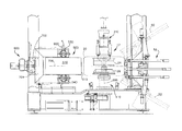
- FIG. 1 is a fragmentary, side elevational view of a tire testing station and load wheel assembly constructed in accordance with a preferred embodiment of the invention
- FIG. 2 is a fragmentary view of the load wheel assembly, portions of which are shown in section;
- FIG. 3 is a top plan view of the load wheel assembly shown in FIG. 2;
- FIG. 4 is a block diagram illustrating a data acquisition method that compensates for erroneous lateral forces or lateral vibrations imparted to the test station and/or load wheel;
- FIG. 5 is a block diagram illustrating a data acquisition method that compensates for erroneous radial forces or radial vibrations.
- FIG. 6 is sectional view of a load wheel constructed in accordance with a preferred embodiment of the invention.
- FIG. 1 illustrates the overall arrangement of a tire uniformity machine that includes an apparatus for reducing the effects of erroneous vibrations on the measurement of force on a tire being tested.
- the overall tire uniformity machine is more fully described in co-pending application Ser. No. 08/988,480 filed on Dec. 10, 1997 and entitled “TIRE UNIFORMITY TESTING SYSTEM”, the subject matter of which is incorporated by reference.
- a copy of the co-pending '480 application is attached as Appendix 1 to this application.
- the tire testing system includes a testing station 12 where a tire is tested and optionally ground to adjust the roundness, mechanically uniformity and/or other physical properties of the tire.
- a tire indicated by reference character 20 (shown in phantom) is delivered to the testing station 12 by a suitable conveyor such as the conveyor disclosed in the above-identified co-pending '480 application so that the tire is clamped between lower and upper rims 24 , 26 of a chuck apparatus.
- the rims 24 , 26 form, respectively, part of a spindle assembly 410 and a moveable chuck assembly 310 .
- the chuck apparatus nay comprise an adjustable width chuck apparatus for a tire testing system that is disclosed in co-pending application Ser. No. 08/988,119, filed on Dec. 10, 1997 and entitled “AUTOMATIC ADJUSTABLE WIDTH CHUCK APPARATUS FOR TIRE TESTING SYSTEMS”, the subject matter which is hereby incorporated by reference.
- the tire is clamped between the rims 24 , 26 and inflated via the chuck apparatus.
- a load wheel 510 forming part of a loadwheel assembly 500 is moved into abutting relationship with the outer surface of the tire 20 .
- the tire is rotated against the load wheel 510 which monitors the load exerted by the tire via load cells 530 , 540 .
- the data taken from the load cells is used to determine the uniformity of the tire. If desired, adjustments to the uniformity of the tire are made by one or more grinders, indicated generally by the reference characters 50 , 52 (shown in phantom).
- the tire testing system includes a probe system indicated generally by the reference character 56 .
- a probe system suitable for use with the illustrated tire testing system is fully disclosed in the above-identified '480 application entitle “TIRE UNIFORMITY TESTING SYSTEMS”, the subject matter of which has been previously incorporated by reference and is contained in Appendix 1.
- the load wheel assembly 500 may have various configurations.
- An example of a suitable load wheel assembly is disclosed in co-pending application Ser. No. 08/988,509, which is hereby incorporated by reference. A copy of the co-pending '509 application is attached as Appendix 2 to this application.
- the load wheel assembly 500 includes three main components, namely, a load wheel 510 , C-shaped carriage 550 and a drive mechanism 600 .
- the illustrated load wheel includes a cylindrical outer wall 512 , the exterior of which contacts the rotating tire held by the chuck assembly, as is known in the art.
- the outer wall 512 of the load wheel 510 is connected to a hub 514 defining a hollow bore 520 .
- Hub 514 is joined to the outer wall 512 by a plurality of solid annular disks 516 , 518 .
- disk 516 are disposed between the hub 514 and outer wall 512 near the opposite ends thereof closing off the hollow interior of the load wheel while disk 518 is disposed between the central portions of hubs 514 and wall 512 . Further details of the illustrative load wheel can be found in the above-identified '509 patent application.
- a C-shaped carriage 550 is shown to include an upper horizontal leg 552 , a lower horizontal leg 554 and a vertical connecting leg 556 extending there between.
- the end portions 553 , 555 of carriage legs 552 , 554 are formed to include step or recessed areas attached to (or alternatively formed integrally width) mounting pads 558 , 560 .
- Pads 558 , 560 mount the spindle ends 522 , 524 of a load wheel spindle 521 and the load cells 530 , 540 .
- the C-shaped frame 552 is supported for sliding movement upon a base 62 a .
- a drive mechanism 600 mounted to vertical frame pieces 68 a , 68 b (see FIG. 3) affects motion in the carriage 552 towards and away from a tire 20 located in the testing station.
- the drive includes a ball screw 640 operatively connected to the load wheel frame 552 at its radial center. Details of the drive mechanism 600 can be found in the above-identified '509 application.
- the disclosed tire uniformity machine includes data acquisition apparatus that compensates for extraneous vibrations and/or forces transmitted to the load cells 530 , 540 which would ordinarily represent errors in the measurement system.
- the apparatus comprises one or more transducers or other sensors that measure or monitor the vibration of the tire testing machine in terms of its acceleration.
- the vibration compensating apparatus includes acceleration transducers strategically mounted on the load wheel assembly 500 .
- the tire uniformity machine measures forces in the “radial” and “lateral” directions.
- the term “lateral” in the tire testing art is defined to refer to forces along the axis of rotation of the tire, in the direction lateral to a tire as it would be oriented on a vehicle. In the tire testing machine shown in FIGS. 1 and 2, the tire is oriented horizontally during the test and thus the “lateral” force is actually directed vertically as viewed in FIGS. 1 and 2.
- the lateral force component acts along a vector that is parallel to the axis of rotation (indicated by the reference character 688 in FIG. 1) of the tire itself.
- the radial component is defined to be along the axis connecting the center of rotation of the tire and the load wheel, and is also directed horizontally, i.e., parallel to a plane of rotation of the tire.
- the lateral component of the vibrations is monitored by an accelerometer 700 that is mounted at or near the axis of rotation 698 for the load wheel 510 .
- the actual mounting location for the lateral accelerometer 700 is offset to one side of the axis since in the illustrated construction, it is impossible to mount the accelerometer precisely on the rotational axis of the load wheel 510 .
- the radial component of the force is monitored by at least one accelerometer 702 mounted to the C-shaped carriage 552 of the load wheel assembly 500 .
- the carriage drive mechanism 600 is attached to the C-shaped carriage at its radial center. This makes it impossible for the accelerometer 702 to be located coincident with a center rotational plane indicated by the phantom line 706 for the load wheel 510 .
- a pair of accelerometers 702 , 704 are disposed on either side of the center plane and are symmetrically spaced about the axis to achieve the desired sensitivity to the force being monitored.
- the acceleration measuring apparatus measure motion in the same direction that the motion of the mass causes the influence on the load cell measurement of force.
- uniformity machines are designed to be sensitive to the indicated forces, with very low sensitivity to the corresponding moment.
- the transducer for measuring acceleration should be mounted on a line which passes through the center of mass of the load wheel assembly in the desired measurement direction, i.e., lateral or radial. In some cases, this may not be possible, for lack of suitable mounting surfaces as is the case with the embodiment shown in FIG. 2 . In these cases, two transducers may be used, symmetrically spaced about the axis to achieve the desired sensitivity to the force while reducing sensitivity to the moment.
- acceleration transducers 700 , 702 and 704 form part of a uniformity testing machine such as that is disclosed in the above-identified co-pending '480 application.
- the load wheel has a mass of approximately 340 pounds.
- Two biaxial load cells 530 , 540 are used to measure radial and lateral force.
- the load cells in the illustrated embodiment are Lebow Model 6443-105, with a range of 500 pounds in the lateral direction, and 2,000 pounds in the radial direction. These cells are summed to provide a total range of 1,000 pounds lateral and 4,000 pounds radial.
- the load cell signals are processed by Akron Standard Instrument Amplifier Cards designated as model 440-0027-XX which are modified as shown in FIGS. 4 and 5.
- the lateral channel includes a signal from the load cells 530 , 540 which is amplified (by amplifier 709 ) and fed to a differential amplifier 710 .
- a signal from the accelerometer 700 is conditioned (by conditioning circuitry 712 ) and scaled (by a factor of 1.36) by a scaler 714 and also fed to the differential amplifier 710 which outputs a net signal that is representative of the actual force variation being measured in the tire being tested.
- the radial channel includes a signal received from the load cells 530 , 540 communicated to another differential amplifier 716 via an amplifier 718 .
- Acceleration related information is communicated by the accelerometers 702 , 704 to the differential amplifier 716 .
- the signals are conditioned and scaled (by signal conditioners 720 , 722 and a scaler 724 ) and are summed with the load cell data resulting in data that does not include the radial force data generated by the erroneous vibrations.
- acceleration transducers denoted as PCB model 393A03 seismic accelerometers have produced satisfactory results.
- Signal conditioners known as PCB model 482A16 were used.
- the transducers 700 , 702 , 704 and the signal conditioners 720 , 722 are available from PCB Piezotronics, Inc. of Depew N.Y.
- accelerometer 700 for measuring the extraneous forces in the lateral direction is mounted to the top of the load carriage 552 substantially vertically above the center of mass of the load wheel 510 .
- the accelerometers 702 , 704 for the radial direction are mounted to the load wheel assembly symmetrically above and below the center of mass of the load wheel since the ball screw 640 (see FIG. 2) which drives the load wheel carriage is located on the radial centerline.
- the signals from the accelerometers 700 , 702 , 704 are scaled by scalers 714 and/or 724 .
- the actual scaling factor for a given accelerometer, such as accelerometer 700 is determined by characteristics of the accelerometer itself.
- the methodology for arriving at an appropriate scaling factor is set out below.
- the scaling factor which is shown as 1.36 in FIG. 4 for the above-identified accelerometer 700 is derived as follows:
- the scaling factor K 4 which is equal to 1.36 for the accelerometer 700 is thus used in the scaler 714 .
- FIG. 6 illustrates an alternate embodiment in which accelerometers are mounted to the load wheel spindle itself.
- the load wheel 510 ′ is rotatably supported on a fixed axle or spindle 521 ′ by a pair of roller bearings 740 , 742 .
- an accelerometer 700 ′ for measuring force in the lateral direction is mounted within a center bore 750 formed in the spindle 521 ′.
- Electrical signal conductors 700 a for the accelerometer 700 ′ are fed from the bore 750 to a suitable controller (not shown) that contains the channel circuitry depicted in FIG. 4 .
- a single accelerometer 702 ′ for measuring forces in the radial direction is positioned in a diametrical bore 760 formed in the spindle 521 ′. Electrical signal carrying conductors 702 a from the radial accelerometer 702 ′ pass from the bore 760 along the outside of the axle 730 and enter the center bore 750 (in which the vertical accelerometer 700 ′ is mounted) via a small cross bore 762 .
- the center bore 750 in which the vertical accelerometer 700 ′ is mounted
- the accelerometers 700 ′, 702 ′ are located precisely along the respective lateral and radial axes of the load wheel assembly and should provide highly accurate data signals that accurately reflect the lateral and radial accelerations imparted to the load wheel assembly by external forces such as vehicular traffic in the plant or internal component movement such as movement in conveyors or grinders.
Landscapes
- Physics & Mathematics (AREA)
- General Physics & Mathematics (AREA)
- Testing Of Balance (AREA)
Abstract
Description
Claims (12)
Priority Applications (1)
| Application Number | Priority Date | Filing Date | Title |
|---|---|---|---|
| US10/030,610 US6834559B1 (en) | 1999-07-09 | 2000-07-06 | Vibration compensation system for tire testing systems |
Applications Claiming Priority (3)
| Application Number | Priority Date | Filing Date | Title |
|---|---|---|---|
| US14300799P | 1999-07-09 | 1999-07-09 | |
| US10/030,610 US6834559B1 (en) | 1999-07-09 | 2000-07-06 | Vibration compensation system for tire testing systems |
| PCT/US2000/018568 WO2001002826A1 (en) | 1999-07-07 | 2000-07-06 | Vibration compensation system for tire testing systems |
Publications (1)
| Publication Number | Publication Date |
|---|---|
| US6834559B1 true US6834559B1 (en) | 2004-12-28 |
Family
ID=33543668
Family Applications (1)
| Application Number | Title | Priority Date | Filing Date |
|---|---|---|---|
| US10/030,610 Expired - Lifetime US6834559B1 (en) | 1999-07-09 | 2000-07-06 | Vibration compensation system for tire testing systems |
Country Status (1)
| Country | Link |
|---|---|
| US (1) | US6834559B1 (en) |
Cited By (7)
| Publication number | Priority date | Publication date | Assignee | Title |
|---|---|---|---|---|
| US20100068418A1 (en) * | 2006-04-13 | 2010-03-18 | Industrial Technology Research Institute | Sensitized Photochemical Switching for Cholesteric Liquid Crystal Displays |
| EP2196789A1 (en) * | 2008-12-10 | 2010-06-16 | Snap-on Equipment Srl a unico socio. | Apparatus for measuring unbalance forces |
| US20120298390A1 (en) * | 2011-05-23 | 2012-11-29 | Illinois Tool Works Inc. | Stud miss indicator for fastener driving tool |
| EP3227657A4 (en) * | 2014-12-02 | 2019-03-20 | Micro-Poise Measurement Systems, LLC | TIRE UNIFORMITY CONTROL SYSTEM |
| CN109596368A (en) * | 2019-02-15 | 2019-04-09 | 江苏江昕轮胎有限公司 | Tire low-temperature test instrument |
| US10335937B2 (en) | 2012-06-05 | 2019-07-02 | Illinois Tool Works Inc. | Fastener-driving tool including a fastening result detector |
| JPWO2018154649A1 (en) * | 2017-02-22 | 2019-12-12 | 三菱重工機械システム株式会社 | Rotating body load measuring device |
Citations (27)
| Publication number | Priority date | Publication date | Assignee | Title |
|---|---|---|---|---|
| US3817003A (en) | 1972-04-05 | 1974-06-18 | Gen Tire & Rubber Co | Harmonic composite grinding of tires |
| US3849942A (en) | 1972-04-05 | 1974-11-26 | Gen Tire & Rubber Co | Harmonic composite grind |
| US3914907A (en) | 1967-02-01 | 1975-10-28 | Gen Tire & Rubber Co | Method for improving the ride characteristics of tires |
| US3987672A (en) | 1974-08-07 | 1976-10-26 | Picker Corporation | Tire inspection system |
| US4024372A (en) | 1975-12-19 | 1977-05-17 | Akron Standard, Division Of Eagle-Picher Industries, Inc. | Method of making a load cell |
| US4191055A (en) | 1978-07-25 | 1980-03-04 | Ransburg Corporation | Dynamic imbalance determining system |
| US4241300A (en) | 1977-03-24 | 1980-12-23 | Eagle-Picher Industries, Inc. | Circuit responsive to rate change in amplitude of analog electrical signal for use in tire processing apparatus |
| GB2104010A (en) | 1981-08-20 | 1983-03-02 | Froude Eng Ltd | >Tyre testing apparatus |
| US4489607A (en) | 1983-05-23 | 1984-12-25 | Park Hyo Sup | Dynamic vehicle tire and wheel balancing system |
| US4489598A (en) | 1983-05-09 | 1984-12-25 | Eagle-Picher Industries, Inc. | Tire rolling resistance measurement system |
| US4576040A (en) | 1983-06-29 | 1986-03-18 | Eagle-Picher Industries, Inc. | Device for measuring extraneous losses in apparatus for measuring the rolling resistance of tires |
| US4704900A (en) | 1986-08-19 | 1987-11-10 | Eagle-Picher Industries, Inc. | Apparatus and method for imposing a desired average radial force on a tire |
| US4805125A (en) | 1987-06-12 | 1989-02-14 | Eagle-Picher Industries, Inc. | Apparatus and methods for improving uniformity measurements |
| US4815004A (en) | 1986-10-17 | 1989-03-21 | Eagle-Picher Industries, Inc. | Apparatus and method for predicting fore/aft forces generated by tires |
| US4852398A (en) | 1988-03-09 | 1989-08-01 | Eagle-Picher Industries, Inc. | Tire testing machine having adjustable bead width |
| US5027649A (en) | 1989-07-06 | 1991-07-02 | Gebr. Hofmann Gmbh & Co. Kg | Process and apparatus for testing the uniformity of pneumatic tires |
| US5052218A (en) | 1989-08-30 | 1991-10-01 | Kabushiki Kaisha Kobe Seiko Sho | Tire uniformity inspecting machine |
| US5067348A (en) | 1989-06-14 | 1991-11-26 | Gebr. Hofmann Gmbh & Co. Kg Maschinenfabrik | Rotary member measuring apparatus with improved support bed |
| US5103595A (en) | 1990-05-14 | 1992-04-14 | Fmc Corporation | Apparatus and method for reducing vibration characteristics in a wheel rim and tire assembly |
| US5448910A (en) * | 1994-03-07 | 1995-09-12 | Bridgestone/Firestone, Inc. | Portable tire uniformity test machine |
| US5614676A (en) * | 1996-03-08 | 1997-03-25 | The Goodyear Tire & Rubber Company | Method of machine vibration analysis for tire uniformity machine |
| WO1998004897A1 (en) | 1996-07-30 | 1998-02-05 | The Goodyear Tire & Rubber Company | Method of enhancing the measurement accuracy of a tire uniformity machine |
| US5979231A (en) | 1997-01-24 | 1999-11-09 | Illinois Tool Works, Inc. | Loadwheel assembly for tire testing systems having conical support plates |
| US5992227A (en) | 1997-01-24 | 1999-11-30 | Jellison; Frank R. | Automatic adjustable width chuck apparatus for tire testing systems |
| US6016695A (en) | 1997-01-24 | 2000-01-25 | Illinois Tool Works Inc. | Tire uniformity testing system |
| US6035709A (en) | 1996-07-30 | 2000-03-14 | The Goodyear Tire & Rubber Company | Method of enhancing the measurement accuracy of a tire uniformity machine |
| US6082191A (en) | 1997-01-24 | 2000-07-04 | Illinois Tool Works, Inc. | Inlet conveyor for tire testing systems |
-
2000
- 2000-07-06 US US10/030,610 patent/US6834559B1/en not_active Expired - Lifetime
Patent Citations (27)
| Publication number | Priority date | Publication date | Assignee | Title |
|---|---|---|---|---|
| US3914907A (en) | 1967-02-01 | 1975-10-28 | Gen Tire & Rubber Co | Method for improving the ride characteristics of tires |
| US3817003A (en) | 1972-04-05 | 1974-06-18 | Gen Tire & Rubber Co | Harmonic composite grinding of tires |
| US3849942A (en) | 1972-04-05 | 1974-11-26 | Gen Tire & Rubber Co | Harmonic composite grind |
| US3987672A (en) | 1974-08-07 | 1976-10-26 | Picker Corporation | Tire inspection system |
| US4024372A (en) | 1975-12-19 | 1977-05-17 | Akron Standard, Division Of Eagle-Picher Industries, Inc. | Method of making a load cell |
| US4241300A (en) | 1977-03-24 | 1980-12-23 | Eagle-Picher Industries, Inc. | Circuit responsive to rate change in amplitude of analog electrical signal for use in tire processing apparatus |
| US4191055A (en) | 1978-07-25 | 1980-03-04 | Ransburg Corporation | Dynamic imbalance determining system |
| GB2104010A (en) | 1981-08-20 | 1983-03-02 | Froude Eng Ltd | >Tyre testing apparatus |
| US4489598A (en) | 1983-05-09 | 1984-12-25 | Eagle-Picher Industries, Inc. | Tire rolling resistance measurement system |
| US4489607A (en) | 1983-05-23 | 1984-12-25 | Park Hyo Sup | Dynamic vehicle tire and wheel balancing system |
| US4576040A (en) | 1983-06-29 | 1986-03-18 | Eagle-Picher Industries, Inc. | Device for measuring extraneous losses in apparatus for measuring the rolling resistance of tires |
| US4704900A (en) | 1986-08-19 | 1987-11-10 | Eagle-Picher Industries, Inc. | Apparatus and method for imposing a desired average radial force on a tire |
| US4815004A (en) | 1986-10-17 | 1989-03-21 | Eagle-Picher Industries, Inc. | Apparatus and method for predicting fore/aft forces generated by tires |
| US4805125A (en) | 1987-06-12 | 1989-02-14 | Eagle-Picher Industries, Inc. | Apparatus and methods for improving uniformity measurements |
| US4852398A (en) | 1988-03-09 | 1989-08-01 | Eagle-Picher Industries, Inc. | Tire testing machine having adjustable bead width |
| US5067348A (en) | 1989-06-14 | 1991-11-26 | Gebr. Hofmann Gmbh & Co. Kg Maschinenfabrik | Rotary member measuring apparatus with improved support bed |
| US5027649A (en) | 1989-07-06 | 1991-07-02 | Gebr. Hofmann Gmbh & Co. Kg | Process and apparatus for testing the uniformity of pneumatic tires |
| US5052218A (en) | 1989-08-30 | 1991-10-01 | Kabushiki Kaisha Kobe Seiko Sho | Tire uniformity inspecting machine |
| US5103595A (en) | 1990-05-14 | 1992-04-14 | Fmc Corporation | Apparatus and method for reducing vibration characteristics in a wheel rim and tire assembly |
| US5448910A (en) * | 1994-03-07 | 1995-09-12 | Bridgestone/Firestone, Inc. | Portable tire uniformity test machine |
| US5614676A (en) * | 1996-03-08 | 1997-03-25 | The Goodyear Tire & Rubber Company | Method of machine vibration analysis for tire uniformity machine |
| WO1998004897A1 (en) | 1996-07-30 | 1998-02-05 | The Goodyear Tire & Rubber Company | Method of enhancing the measurement accuracy of a tire uniformity machine |
| US6035709A (en) | 1996-07-30 | 2000-03-14 | The Goodyear Tire & Rubber Company | Method of enhancing the measurement accuracy of a tire uniformity machine |
| US5979231A (en) | 1997-01-24 | 1999-11-09 | Illinois Tool Works, Inc. | Loadwheel assembly for tire testing systems having conical support plates |
| US5992227A (en) | 1997-01-24 | 1999-11-30 | Jellison; Frank R. | Automatic adjustable width chuck apparatus for tire testing systems |
| US6016695A (en) | 1997-01-24 | 2000-01-25 | Illinois Tool Works Inc. | Tire uniformity testing system |
| US6082191A (en) | 1997-01-24 | 2000-07-04 | Illinois Tool Works, Inc. | Inlet conveyor for tire testing systems |
Cited By (13)
| Publication number | Priority date | Publication date | Assignee | Title |
|---|---|---|---|---|
| US20100068418A1 (en) * | 2006-04-13 | 2010-03-18 | Industrial Technology Research Institute | Sensitized Photochemical Switching for Cholesteric Liquid Crystal Displays |
| EP2196789A1 (en) * | 2008-12-10 | 2010-06-16 | Snap-on Equipment Srl a unico socio. | Apparatus for measuring unbalance forces |
| US8671734B2 (en) | 2008-12-10 | 2014-03-18 | Snap-On Equipment Srl A Unico Socio | Apparatus for measuring unbalance forces |
| CN101750189B (en) * | 2008-12-10 | 2014-09-10 | 施耐宝仪器股份有限公司 | Apparatus for measuring unbalance forces |
| US20120298390A1 (en) * | 2011-05-23 | 2012-11-29 | Illinois Tool Works Inc. | Stud miss indicator for fastener driving tool |
| US10442065B2 (en) * | 2011-05-23 | 2019-10-15 | Illinois Tool Works Inc. | Stud miss indicator for fastener driving tool |
| US10335937B2 (en) | 2012-06-05 | 2019-07-02 | Illinois Tool Works Inc. | Fastener-driving tool including a fastening result detector |
| US10782209B2 (en) | 2014-12-02 | 2020-09-22 | Micro-Poise Measurement Systems Llc | Tire uniformity testing machine and a load wheel carriage assembly for a tire uniformity machine |
| EP3227657A4 (en) * | 2014-12-02 | 2019-03-20 | Micro-Poise Measurement Systems, LLC | TIRE UNIFORMITY CONTROL SYSTEM |
| US11549863B2 (en) | 2014-12-02 | 2023-01-10 | Micro-Poise Measurement Systems Llc | Tire uniformity testing machine |
| JPWO2018154649A1 (en) * | 2017-02-22 | 2019-12-12 | 三菱重工機械システム株式会社 | Rotating body load measuring device |
| US11243136B2 (en) | 2017-02-22 | 2022-02-08 | Mitsubishi Heavy Industries Machinery Systems, Ltd. | Rotating body load measuring device |
| CN109596368A (en) * | 2019-02-15 | 2019-04-09 | 江苏江昕轮胎有限公司 | Tire low-temperature test instrument |
Similar Documents
| Publication | Publication Date | Title |
|---|---|---|
| JP2008507695A (en) | Lateral load tire test system | |
| CA1178088A (en) | Tire dynamic imbalance screening system | |
| CN108072490B (en) | Dynamic balancer | |
| EP3163282B1 (en) | Method for characterizing tire uniformity machines | |
| US6834559B1 (en) | Vibration compensation system for tire testing systems | |
| US6907781B2 (en) | Wheel balancing system with integrated wheel lift, loaded mode testing, and wheel imaging system | |
| US6035709A (en) | Method of enhancing the measurement accuracy of a tire uniformity machine | |
| US4787150A (en) | Fixture for checking the alignment of a loadwheel with the spindle of a tire uniformity machine | |
| US4055081A (en) | Method and apparatus for improving the ride characteristics of motor vehicle wheels | |
| US6575024B2 (en) | Apparatus and method for testing tires and calibrating flat belt tire testing machines | |
| US8943881B2 (en) | System for characterizing tire uniformity machines and methods of using the characterizations | |
| EP1203213B1 (en) | Vibration compensation system for tire testing systems | |
| JP4741126B2 (en) | Vibration correction system for tire test system | |
| US4545239A (en) | Method and apparatus for controlling the quality of tires | |
| JP2004537711A5 (en) | ||
| JP2003021572A (en) | Impact test equipment for rolling bearings | |
| WO1998008070A1 (en) | Method of balance screening a pneumatic tire with a tire uniformity machine | |
| WO1998004897A1 (en) | Method of enhancing the measurement accuracy of a tire uniformity machine | |
| US6931911B1 (en) | Dynamic calibrator | |
| EP3572780B1 (en) | Rotary-body load measurement device | |
| JPS63241302A (en) | Apparatus for inspecting deflection of wheel | |
| JPH05203530A (en) | Tire-uniformity measuring method | |
| JPS647300Y2 (en) | ||
| JPS6311614B2 (en) | ||
| SU1746245A1 (en) | Test bed for measuring vehicleъs wheels toe-in and camber |
Legal Events
| Date | Code | Title | Description |
|---|---|---|---|
| AS | Assignment |
Owner name: ILLINOIS TOOL WORKS, INC., ILLINOIS Free format text: ASSIGNMENT OF ASSIGNORS INTEREST;ASSIGNOR:BEEBE, JAMES C.;REEL/FRAME:012978/0586 Effective date: 20020107 |
|
| STCF | Information on status: patent grant |
Free format text: PATENTED CASE |
|
| AS | Assignment |
Owner name: GMAC COMMERCIAL FINANCE LLC, NEW YORK Free format text: SECURITY AGREEMENT;ASSIGNOR:MICRO-POISE MEASUREMENT SYSTERM, LLC;REEL/FRAME:019161/0292 Effective date: 20070403 |
|
| AS | Assignment |
Owner name: MICRO-POISE MEASUREMENT SYSTEMS, LLC, A DELAWARE L Free format text: ASSIGNMENT OF ASSIGNORS INTEREST;ASSIGNOR:ILLINOIS TOOL WORKS, INC., A DELAWARE CORPORATION;REEL/FRAME:019419/0927 Effective date: 20070403 |
|
| FPAY | Fee payment |
Year of fee payment: 4 |
|
| AS | Assignment |
Owner name: GMAC COMMERCIAL FINANCE LLC, NEW YORK Free format text: THIS IS A CORECTIVE FILING TO CORRECT THE PATENT NUMBER WHICH WAS ORIGINALLY INDEX AS 11103099 BUT SHOULD BE 111103090 AS CAN BE FOUND ON THE LIST OF PATENT NUMBERS IN SCHEDULE A. THIS SECURITY AGREEMENT WAS ORIGINALLY FILED ON 04/03/2007 IN REEL/FRAME 019161/0292.;ASSIGNOR:MICRO-POISE MEASUREMENT SYSTEM, LLC;REEL/FRAME:023699/0028 Effective date: 20070403 |
|
| FEPP | Fee payment procedure |
Free format text: PAYOR NUMBER ASSIGNED (ORIGINAL EVENT CODE: ASPN); ENTITY STATUS OF PATENT OWNER: LARGE ENTITY Free format text: PAT HOLDER CLAIMS SMALL ENTITY STATUS, ENTITY STATUS SET TO SMALL (ORIGINAL EVENT CODE: LTOS); ENTITY STATUS OF PATENT OWNER: LARGE ENTITY |
|
| FPAY | Fee payment |
Year of fee payment: 8 |
|
| FEPP | Fee payment procedure |
Free format text: PAT HOLDER NO LONGER CLAIMS SMALL ENTITY STATUS, ENTITY STATUS SET TO UNDISCOUNTED (ORIGINAL EVENT CODE: STOL); ENTITY STATUS OF PATENT OWNER: LARGE ENTITY |
|
| FPAY | Fee payment |
Year of fee payment: 12 |
|
| SULP | Surcharge for late payment |