US683409A - Process of making gas. - Google Patents
Process of making gas. Download PDFInfo
- Publication number
- US683409A US683409A US6763201A US1901067632A US683409A US 683409 A US683409 A US 683409A US 6763201 A US6763201 A US 6763201A US 1901067632 A US1901067632 A US 1901067632A US 683409 A US683409 A US 683409A
- Authority
- US
- United States
- Prior art keywords
- gas
- generator
- regenerator
- valve
- air
- Prior art date
- Legal status (The legal status is an assumption and is not a legal conclusion. Google has not performed a legal analysis and makes no representation as to the accuracy of the status listed.)
- Expired - Lifetime
Links
- 238000000034 method Methods 0.000 title description 10
- 239000007789 gas Substances 0.000 description 27
- 239000000446 fuel Substances 0.000 description 17
- XEEYBQQBJWHFJM-UHFFFAOYSA-N Iron Chemical compound [Fe] XEEYBQQBJWHFJM-UHFFFAOYSA-N 0.000 description 8
- 238000002485 combustion reaction Methods 0.000 description 7
- XLYOFNOQVPJJNP-UHFFFAOYSA-N water Substances O XLYOFNOQVPJJNP-UHFFFAOYSA-N 0.000 description 6
- 238000007664 blowing Methods 0.000 description 4
- 229910052742 iron Inorganic materials 0.000 description 4
- 238000004519 manufacturing process Methods 0.000 description 4
- 239000002956 ash Substances 0.000 description 3
- 239000011449 brick Substances 0.000 description 3
- 238000004140 cleaning Methods 0.000 description 3
- 239000003245 coal Substances 0.000 description 3
- 238000010438 heat treatment Methods 0.000 description 3
- 239000002184 metal Substances 0.000 description 3
- 229910052751 metal Inorganic materials 0.000 description 3
- 235000002918 Fraxinus excelsior Nutrition 0.000 description 2
- 239000000571 coke Substances 0.000 description 2
- 239000000470 constituent Substances 0.000 description 2
- 230000000694 effects Effects 0.000 description 2
- 229930195733 hydrocarbon Natural products 0.000 description 2
- 150000002430 hydrocarbons Chemical class 0.000 description 2
- -1 ordinary coal Chemical class 0.000 description 2
- 238000000197 pyrolysis Methods 0.000 description 2
- 239000011819 refractory material Substances 0.000 description 2
- 241001556567 Acanthamoeba polyphaga mimivirus Species 0.000 description 1
- OKTJSMMVPCPJKN-UHFFFAOYSA-N Carbon Chemical compound [C] OKTJSMMVPCPJKN-UHFFFAOYSA-N 0.000 description 1
- 239000004215 Carbon black (E152) Substances 0.000 description 1
- 241000948268 Meda Species 0.000 description 1
- 229910052799 carbon Inorganic materials 0.000 description 1
- 238000005336 cracking Methods 0.000 description 1
- 238000005520 cutting process Methods 0.000 description 1
- 239000001257 hydrogen Substances 0.000 description 1
- 229910052739 hydrogen Inorganic materials 0.000 description 1
- 125000004435 hydrogen atom Chemical class [H]* 0.000 description 1
- 210000003141 lower extremity Anatomy 0.000 description 1
- 239000000463 material Substances 0.000 description 1
- 238000005201 scrubbing Methods 0.000 description 1
- 239000000779 smoke Substances 0.000 description 1
- 239000007921 spray Substances 0.000 description 1
- 239000002023 wood Substances 0.000 description 1
Images


Classifications
-
- C—CHEMISTRY; METALLURGY
- C10—PETROLEUM, GAS OR COKE INDUSTRIES; TECHNICAL GASES CONTAINING CARBON MONOXIDE; FUELS; LUBRICANTS; PEAT
- C10J—PRODUCTION OF PRODUCER GAS, WATER-GAS, SYNTHESIS GAS FROM SOLID CARBONACEOUS MATERIAL, OR MIXTURES CONTAINING THESE GASES; CARBURETTING AIR OR OTHER GASES
- C10J3/00—Production of combustible gases containing carbon monoxide from solid carbonaceous fuels
Definitions
- My invention comprises an improved man ufacture of gas for heating, lighting, and other purposes.
- the said gas is made from coal, coke, wood, or other carbonaceous or combustible substancesin conjunction with water in an apparatus constructed and working as hereinafter described, and by the said manufacture,apparatus,and particular working volatile hydrocarbons, such as ordinary coal, as well as carbon, such as coke or an thracite coal, can be converted into a gas for industrial uses without splitting up, cracking, or otherwise prejudicially afiecting the volatile product.
- the apparatus for carrying out my invention is characterized by a generator or producer, a regenerator, a system of valves, and an annular air-space and passages, operating and controlling mechanism for said valves, and devices and propelling means for blowing air into the generator or producer and for supplying water or steam to the regenerator.
- the generator or producer a consists of a vertical metal casing 1, thickly lined with fire-brick or other suitable refractory material 2 and provided at the top with a hopper 3, for the supply of the fuel tobe converted into gas.
- the generator at has in its walls a number (in the example three) of air-inlet pipes and passages 4, disposed at difother fittings common to similar furnaces and not, therefore, necessary to more particularly describe or illustrate, and at its base a fireplace 6 is provided for the initial starting of the apparatus.
- At the bottom of the generator there is an outlet through which the ashes fall into an ash pan or trough 7, which is kept nearly full of water in order to seal the outlet and keep the generator gas-tight.
- the generator is connected at its base by a passage 8 with the base of a regenerator 17, consisting of a vertical metal casing 1, thickly lined with refractory material 2 and partly filled with fire-brick checker-work 9 and partly with checker-work of iron 10 or other material not liable to disintegrate under the action of moisture and heat.
- a regenerator 17 At its upper end the regenerator b is connected with a chimney 11, which is opened and closed bya valve, and at some suitable point in the regenerator, preferably near the base, is an airinlet pipe and passage 12, fitted with a valve in a casing 13, and a scavenging-outlet 14:, fitted with a valve in a casing 15.
- the regenerator has also sight-holes (not shown) for enabling its interior to be inspected and a suitable door 16, for cleaning purposes.
- a revolving distributor l7 supplied with water, as required, through a pipe 18, controlled by a tap or valve.
- the distributer 17 is revolved by a pair of bevel-gears 19, shaft 20, belt-pulley 21, belt 22, and pulley 23 on a shaft 24:, which is driven by a pulley 25., belt 26, and pulley 27 from a shaft 28, which is driven in any convenient manner from a gas-engine or other suitable motor and has mounted on it the cams for actuating the several gas and air valves by the following or any other'convenessjioe ient arrangement of mechanism.
- each elbow-lever has an antifrictionroller 31 at its end contiguous to its cam, while at the other end it is connected by a rod 32 to the valve which it controls.
- the cam 33 through its elbow-lever 30 and connecting-rod 32, opens and closes the valve in the casing 34, which controls the gas-outlet pipe 5 from the top of the generator at.
- the cam 41 opens and closes the valve in the casing 13, controlling the air-inlet 12 to the passage 8 between the generator and regenerator
- the cam 42 opens and closes the valve in the casing 15, controlling the scavenging-outlet 14 from the regenerator
- the cam 43 opens and closes the valve in the casing 44, controlling the outlet at the top of the regenerator to the chimney 11.
- the fresh fuel owing to the high temperature of the generator, at once volatilizes to the extent of giving off a combustible gas which may be allowed to pass ofi through the gas-outlet pipe 5 to a holder, (not shown,) whence it may be conducted to the gas-engine (where such is employed) and utilized to run the engine for a few turns while starting the apparatus. Then the gas-valve 34 is closed and the outlet-valve 44 from the regenerator to the chimney is opened and the ordinary working of the apparatus now begins. First, air is blown into the generator from a suitable fan or equivalent, (not shown,) connected to a pipe 46, leading to the pipes and passages 4 and 12.
- the air passes down through the highly-heated mass of fuel first from the highest air-inlet 4 and then from the next in order lower down, the valves 38 39 40 of said inlets being opened and closed by their respective cams to bring the said air-inlets progressively into action, and thereby create a series of zones of high temperature at different heights which combine to constitute a column of incandescent fuel.
- the gaseous products of combustion pass from the generator a into the lower extremity of the regenerator b and in their passage meet a supplementary supply of air admitted by the valve 13 through the air-inlet 12,whereby complete combustion iseffected.
- the scavenging-valve 15 is only opened for a very brief period and immediately it is closed the gas-outlet valve 34 of the generator is opened.
- the steam now superheated passes along the passage 8 up through the column of incandescent fuel in the generator and'in so ,doing'becomes decomposed into its constituents, hydrogen, carbonic-oxid,and other gases being produced.
- These gases now pass up through -the green or raw fuel at the top of the generator and subject it to destructive distillation, the hydrocarbon and other vapor thereby liberated mixing with the said gases and passing away with them through the gas outlet pipe 5 to the gas-holder.
- a smoke pipe or passage 45 (controlled by a valve) may be em-' ployed leading from the upper part to the lower part of the generator.
- the effect of this pipe or passage is by providing an outlet in the upper part of the generator to cause an updraft of part of the blast introduced through the air-inlet passages.
- any suitable and known means for scrubbing and purifying the gas may be employed, if required, for illuminating or certain other purposes; but for heating or the like thegas may be used as produced. 1
- the blowing period in the generator recommences.
- water-gas is first formed and then is converted into a richer gas by its passage through and its action upon the green or raw fuel.
- the apparatus may be operated by any convenient motor, and if a gas-engine be employed the gas-producing plant is intended to make the gas necessary for the engine, and this engine will, through the shafts, cams, and connecting mechanism, effect the automatic working of the apparatus.
Landscapes
- Chemical & Material Sciences (AREA)
- Engineering & Computer Science (AREA)
- Combustion & Propulsion (AREA)
- Oil, Petroleum & Natural Gas (AREA)
- Organic Chemistry (AREA)
- Output Control And Ontrol Of Special Type Engine (AREA)
Description
No. 683,409. Patented Sept. 24, l90l.
H. LANE.
PROCESS OF MAKING GAS.
(Application filed July 9. 1901.) (No Model.) 5 Sheets-Shunt 1.
Fl 0. I.
m: NORRIS wnsas co. morauruou wAsmuo'rou. u c.
No. 683,409. Patented Sept. 24, I90l.
H. LANE.
PROCESS OF MAKING GAS.
(Application filed July 9, 1901.) (No Model.) 5 Sheets-Sheet 2.
52W Ill {X Y J 5; 3/ 1 .2- 1. 3.? HM! 35/ mm/r0 w/nv-ssses; M we I Arron/v5 rs.
m: NORRIS PETERS c0. Pnaf'uumm WASHINDTON. n. c.
No. 683,409. Patented Sept. 24, l90l. H. LANE.
PROCESS OF MAKING GAS.
(Application filed July 9, 1901.)
5 Sheets-Sheet 3.
(No Model.)
MIMI
WITNESSES.-
No" 683,409. Patented Sept. 24, I90l.
H. LANE.
PROCESS OF MAKING GAS.
(Application filed luly 9, 1901.) (No Model.) 5Sheets-Sheet 4.
m: Meda s PETERS do. Pnurc utno WASHINGTON, n. c.
(No Model.)
Patented Sept. 24, l90l.,
H. LANE.
PROCESS OF MAKING GAS.
(Application filed July 9, 1901.
5 Sheets-Sheet 5.
lN-VENTO. 4
A TTORNEYS UNITED STATES PATENT OFFICE.
HOWARD LANE, OE BIRMINGHAM, ENGLAND.
PROCESS OF MAKING GAS.
SPECIFICATION forming part of Letters Patent No. 683,409, dated September 24, 1901; Application filed July 9; 1901. Serial No. 67,632. (No specimens.)
Tb all whom, it may concern.-
Be it known that I, HOWARD LANE, mechanical engineer, a subject of the King of Great Britain, residing at 6 Corporation street, Birmingham, in the county of Warwick, England, have invented certain new and useful Improvements in the Manufacture of Gas for Lighting, Heating, and other Purposes, of which the following is a specification.
My invention comprises an improved man ufacture of gas for heating, lighting, and other purposes. The said gas is made from coal, coke, wood, or other carbonaceous or combustible substancesin conjunction with water in an apparatus constructed and working as hereinafter described, and by the said manufacture,apparatus,and particular working volatile hydrocarbons, such as ordinary coal, as well as carbon, such as coke or an thracite coal, can be converted into a gas for industrial uses without splitting up, cracking, or otherwise prejudicially afiecting the volatile product.
The apparatus for carrying out my invention is characterized by a generator or producer, a regenerator, a system of valves, and an annular air-space and passages, operating and controlling mechanism for said valves, and devices and propelling means for blowing air into the generator or producer and for supplying water or steam to the regenerator.
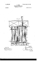
In the accompanying five sheets of drawings I illustrate apparatus for the purposes of my invention, in which- Figure 1 is a vertical section, Fig. 2 a side elevation, and Fig. 3 a front elevation, of apparatus, in which the generator and regenerator are shown as separate vessels. Fig. 4 is a vertical section, and Fig. 5 a front elevation, of apparatus, in which the generator and regenerator are combined in one vessel or casing.
Similar letters and numerals refer to similar parts throughout the several views.
In Figs. 1, 2, and 3 the generator or producer a consists of a vertical metal casing 1, thickly lined with fire-brick or other suitable refractory material 2 and provided at the top with a hopper 3, for the supply of the fuel tobe converted into gas. The generator at has in its walls a number (in the example three) of air-inlet pipes and passages 4, disposed at difother fittings common to similar furnaces and not, therefore, necessary to more particularly describe or illustrate, and at its base a fireplace 6 is provided for the initial starting of the apparatus. At the bottom of the generator there is an outlet through which the ashes fall into an ash pan or trough 7, which is kept nearly full of water in order to seal the outlet and keep the generator gas-tight. The ashes as they fall can be raked out periodically and removed from the ash-pan. The generator is connected at its base by a passage 8 with the base of a regenerator 17, consisting of a vertical metal casing 1, thickly lined with refractory material 2 and partly filled with fire-brick checker-work 9 and partly with checker-work of iron 10 or other material not liable to disintegrate under the action of moisture and heat. At its upper end the regenerator b is connected with a chimney 11, which is opened and closed bya valve, and at some suitable point in the regenerator, preferably near the base, is an airinlet pipe and passage 12, fitted with a valve in a casing 13, and a scavenging-outlet 14:, fitted with a valve in a casing 15. The regenerator has also sight-holes (not shown) for enabling its interior to be inspected and a suitable door 16, for cleaning purposes.
In the regenerator above the iron checkerwork 10 is mounted a revolving distributor l7, supplied with water, as required, through a pipe 18, controlled by a tap or valve. (Not shown.) The distributer 17is revolved by a pair of bevel-gears 19, shaft 20, belt-pulley 21, belt 22, and pulley 23 on a shaft 24:, which is driven by a pulley 25., belt 26, and pulley 27 from a shaft 28, which is driven in any convenient manner from a gas-engine or other suitable motor and has mounted on it the cams for actuating the several gas and air valves by the following or any other'convenessjioe ient arrangement of mechanism. There is a rod or shaft 29 fixed parallel to the shaft 28, and on this rod 29 are pivoted loosely as many elbow-levers 30 as there are cams on the shaft 28, and each elbow-lever has an antifrictionroller 31 at its end contiguous to its cam, while at the other end it is connected by a rod 32 to the valve which it controls. Thus the cam 33, through its elbow-lever 30 and connecting-rod 32, opens and closes the valve in the casing 34, which controls the gas-outlet pipe 5 from the top of the generator at. The cams 35 36 3'7, through their respective elbowlevers 30 and connecting-rods 32, open and close the valves in the casings 38 39 40, which control the air-blast supplied to the several inlets 4 of the generator. In like manner the cam 41 opens and closes the valve in the casing 13, controlling the air-inlet 12 to the passage 8 between the generator and regenerator, the cam 42 opens and closes the valve in the casing 15, controlling the scavenging-outlet 14 from the regenerator, and the cam 43 opens and closes the valve in the casing 44, controlling the outlet at the top of the regenerator to the chimney 11.
When starting the apparatus, a little fuel is fed throughthe hopper 3 into the interior of the generator and afire is started in the fireplace 6 beneath it, the cleaning and poking orifices being open at the time. As the fuel burns, the cleaning and poking orifices are closed, and a fresh supply of fuel is gradually fed in through the hopper 3'until the whole mass Within the interior becomes highly heat-- ed. The fresh fuel, owing to the high temperature of the generator, at once volatilizes to the extent of giving off a combustible gas which may be allowed to pass ofi through the gas-outlet pipe 5 to a holder, (not shown,) whence it may be conducted to the gas-engine (where such is employed) and utilized to run the engine for a few turns while starting the apparatus. Then the gas-valve 34 is closed and the outlet-valve 44 from the regenerator to the chimney is opened and the ordinary working of the apparatus now begins. First, air is blown into the generator from a suitable fan or equivalent, (not shown,) connected to a pipe 46, leading to the pipes and passages 4 and 12. The air passes down through the highly-heated mass of fuel first from the highest air-inlet 4 and then from the next in order lower down, the valves 38 39 40 of said inlets being opened and closed by their respective cams to bring the said air-inlets progressively into action, and thereby create a series of zones of high temperature at different heights which combine to constitute a column of incandescent fuel. During the blowing period,as described,the gaseous products of combustion pass from the generator a into the lower extremity of the regenerator b and in their passage meet a supplementary supply of air admitted by the valve 13 through the air-inlet 12,whereby complete combustion iseffected. After this the gaseous products ascend up the interior of the regenerator, first through the fire-brick checker-work 9, and then through the iron checker-work l0,which absorb the heat from the products before they escape up the chimney. When the regenerator has become highly heated, the blowing period is'terminated and all the air- valves 38, 39, 40, and 13 are closed, as well as the valve 44, controlling the outlet to the chimney 11. The scavenging-valve 15 is then opened, and the tap or valve of the water-supply is also opened by hand or automatically by means of a cam and connections, (not shown,) so that water is sprayed upon the heated iron checker work 10 and is instantly converted into steam;
which passes downward through the interiorof the regenerator and displacing the remnant of combustion products therein scours them out through the scavenging-opening 14. The scavenging-valve 15 is only opened for a very brief period and immediately it is closed the gas-outlet valve 34 of the generator is opened. The steam now superheated passes along the passage 8 up through the column of incandescent fuel in the generator and'in so ,doing'becomes decomposed into its constituents, hydrogen, carbonic-oxid,and other gases being produced. These gases now pass up through -the green or raw fuel at the top of the generator and subject it to destructive distillation, the hydrocarbon and other vapor thereby liberated mixing with the said gases and passing away with them through the gas outlet pipe 5 to the gas-holder.
i To facilitate combustion and prevent cak ing or clinkering of such fuel in the generator a as has that tendency, a smoke pipe or passage 45 (controlled by a valve) may be em-' ployed leading from the upper part to the lower part of the generator. The effect of this pipe or passage is by providing an outlet in the upper part of the generator to cause an updraft of part of the blast introduced through the air-inlet passages. I
Any suitable and known means for scrubbing and purifying the gas may be employed, if required, for illuminating or certain other purposes; but for heating or the like thegas may be used as produced. 1 On the termination of the gasu'naking period the blowing period in the generator recommences. Thus it will be seen that water-gas is first formed and then is converted into a richer gas by its passage through and its action upon the green or raw fuel. As already stated, the apparatus may be operated by any convenient motor, and if a gas-engine be employed the gas-producing plant is intended to make the gas necessary for the engine, and this engine will, through the shafts, cams, and connecting mechanism, effect the automatic working of the apparatus. It will be readily understood that the here in-described process of gas production could be carried out in other forms of apparatus suitably arranged for carrying out the cycle of operations specified, and as an example one such alternative arrangement of apparatus is illustrated in Figs. 4 and 5. -In these views the generator at and the regenerator b are shown combined within one metal casing 1, the regenerator taking the form of an annular chamber or jacket surrounding the generator. In this arrangement only two air blasts or inlets 4 are shown to the generator; but the method of working and the order of the cycle of operations is identically the same as that already described.
What I claim, and desire to secure by Let ters Patent, is-- The herein-described process of making gas, consisting in introducing an air-blast be neath the raw fuel, forcing the gaseous products of combustion downward through the burning fuel located beneath the raw fuel, causing the gaseous products after leaving the burning fuel to flow upward to heat checker=work in a rege'nerator-chamber, furnishing a supply of air to the gaseous products of combustion before they reach the re= generator in order to complete combustion; then cutting off the air-supply and generating steam by causing water to contact in the ,form of spray with the highly-heated checkerup through the coked and raw fuel, the su-' perheated steam being decomposed into its constituent gases and the raw fuel being sub jected to destructive distillation by the upward-flowing gases, the new gaseous products being formed by the admixture of the vapor with the upward-flowing gases, substantially as described.
In witness whereof I have hereunto set my hand in presence of two witnesses.
HOWARD LANE. Witnesses:
HENRY B. BARLOW, HERBERT R. ABBEY.
Priority Applications (1)
| Application Number | Priority Date | Filing Date | Title |
|---|---|---|---|
| US6763201A US683409A (en) | 1901-07-09 | 1901-07-09 | Process of making gas. |
Applications Claiming Priority (1)
| Application Number | Priority Date | Filing Date | Title |
|---|---|---|---|
| US6763201A US683409A (en) | 1901-07-09 | 1901-07-09 | Process of making gas. |
Publications (1)
| Publication Number | Publication Date |
|---|---|
| US683409A true US683409A (en) | 1901-09-24 |
Family
ID=2751952
Family Applications (1)
| Application Number | Title | Priority Date | Filing Date |
|---|---|---|---|
| US6763201A Expired - Lifetime US683409A (en) | 1901-07-09 | 1901-07-09 | Process of making gas. |
Country Status (1)
| Country | Link |
|---|---|
| US (1) | US683409A (en) |
-
1901
- 1901-07-09 US US6763201A patent/US683409A/en not_active Expired - Lifetime
Similar Documents
| Publication | Publication Date | Title |
|---|---|---|
| US683409A (en) | Process of making gas. | |
| US683300A (en) | Apparatus for the manufacture of gas. | |
| US404404A (en) | Apparatus for the manufacture of fuel and illuminating gas | |
| US716455A (en) | Method of producing gas from peat. | |
| US404205A (en) | Process of and apparatus for the manufacture of gas | |
| US290926A (en) | Process of and apparatus for manufacturing gas | |
| US688120A (en) | Process of manufacturing gas. | |
| US882908A (en) | Method of manufacturing gas. | |
| US522687A (en) | Apparatus for manufacturing gas | |
| US644806A (en) | Apparatus for manufacturing gas. | |
| US500424A (en) | Apparatus for the manufacture of gas | |
| US130383A (en) | Improvement in processes and apparatus for making gas | |
| US339471A (en) | Process of and apparatus for manufacturing gas | |
| US389103A (en) | Apparatus for manufacturing gas | |
| US487616A (en) | Apparatus for manufacturing gas | |
| US207413A (en) | Improvement in processes and apparatus for manufacturing water-gas | |
| US437098A (en) | Gas-producer | |
| US472077A (en) | Apparatus for the manufacture of gas | |
| US795208A (en) | Apparatus for the generation of gas. | |
| US300466A (en) | hanlon | |
| US1066296A (en) | Apparatus for treating furnace-gases and preparing fuel. | |
| US893462A (en) | Method of producing gas. | |
| US478459A (en) | Method of manufacturing gas | |
| US334700A (en) | geangee | |
| US314486A (en) | spring-be |