US6834088B2 - Method and apparatus for calculating bit log-likelihood ratios for QAM signals - Google Patents
Method and apparatus for calculating bit log-likelihood ratios for QAM signals Download PDFInfo
- Publication number
- US6834088B2 US6834088B2 US09/804,585 US80458501A US6834088B2 US 6834088 B2 US6834088 B2 US 6834088B2 US 80458501 A US80458501 A US 80458501A US 6834088 B2 US6834088 B2 US 6834088B2
- Authority
- US
- United States
- Prior art keywords
- symbol
- bits
- bit
- predetermined
- symbols
- Prior art date
- Legal status (The legal status is an assumption and is not a legal conclusion. Google has not performed a legal analysis and makes no representation as to the accuracy of the status listed.)
- Expired - Lifetime, expires
Links
Images


Classifications
-
- H—ELECTRICITY
- H04—ELECTRIC COMMUNICATION TECHNIQUE
- H04L—TRANSMISSION OF DIGITAL INFORMATION, e.g. TELEGRAPHIC COMMUNICATION
- H04L27/00—Modulated-carrier systems
- H04L27/32—Carrier systems characterised by combinations of two or more of the types covered by groups H04L27/02, H04L27/10, H04L27/18 or H04L27/26
- H04L27/34—Amplitude- and phase-modulated carrier systems, e.g. quadrature-amplitude modulated carrier systems
- H04L27/38—Demodulator circuits; Receiver circuits
-
- H—ELECTRICITY
- H04—ELECTRIC COMMUNICATION TECHNIQUE
- H04L—TRANSMISSION OF DIGITAL INFORMATION, e.g. TELEGRAPHIC COMMUNICATION
- H04L25/00—Baseband systems
- H04L25/02—Details ; arrangements for supplying electrical power along data transmission lines
- H04L25/06—Dc level restoring means; Bias distortion correction ; Decision circuits providing symbol by symbol detection
- H04L25/067—Dc level restoring means; Bias distortion correction ; Decision circuits providing symbol by symbol detection providing soft decisions, i.e. decisions together with an estimate of reliability
Definitions
- the present invention relates generally to communications systems, and more particularly to methods for demodulating and decoding encoded data bits transmitting in a code division multiple access (CDMA) system.
- CDMA code division multiple access
- the communication path used by such systems has various limitations, such as bandwidth.
- bandwidth As a result, there are upper practical limitations that restrict the quantity of information that can be supported by the communication path over a given period of time.
- modulation techniques have been proposed that effectively increase the information handling capacity of the communication path as measured against other modulation techniques.
- QAM M-ary quadrature amplitude modulation
- QAM provides a constellation of an M number of modulation values (distinguished from one another by each having a different combination of phase and amplitude) wherein each constellation point represents a plurality of information bits.
- M-ary quadrature amplitude modulation provides a constellation of an M number of modulation values (distinguished from one another by each having a different combination of phase and amplitude) wherein each constellation point represents a plurality of information bits.
- M-ary quadrature amplitude modulation In order to achieve greater spectral efficiency in CDMA systems, for example, higher order modulations are used.
- the number of bits that are represented by each symbol in an M-ary QAM system is equal to log M.
- 16 QAM uses 16 distinct constellation points (four points in each quadrant of a complex Cartesian plane having I and Q axes) that each represent log 2 16 or four information bits.
- 64-QAM wherein 64 constellation points each represent a combination of log 264 or six information
- FIG. 1 illustrates a constellation for a 64-QAM communication system that is a map of 64 points each representing a combination of six bits on the complex plane defined by a horizontal axis representing the real portions (i.e., I) and a vertical axis representing imaginary portions (i.e., Q) of a complex number.
- Transmitted QAM information symbols on a communication channel (and the pilot and sync symbols as well) are discrete packets of a carrier signal modulated to convey information using both the amplitude and phase-angle displacement of the carrier from some reference.
- QAM information symbols are represented on the constellation of FIG. 1 as complex quantities represented as vectors having both magnitude (represented as length or distance from origin) and phase angles ⁇ (angles measured with respect to one of the axes).
- each of the 64 points on the constellation is identified as representing one combination of six bits.
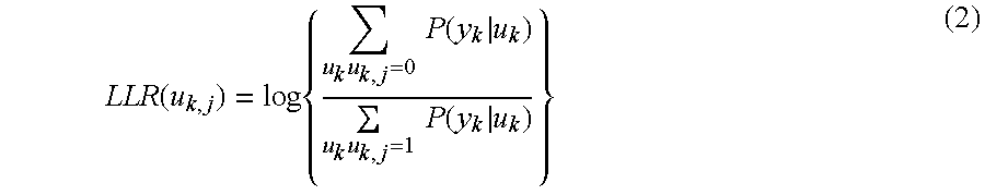
- the demodulator preferably should provide the decoder with the log-likelihood ratio (LLR) of the received encoded bits.
- LLR log-likelihood ratio
- a receiver 200 in a CDMA system includes a log-likelihood ratio calculator 202 that receives demodulated symbols from a demodulator 204 and calculates a LLR for each bit of the demodulated symbols.
- the decoder 206 receives the LLR's calculated by the log-likelihood ratio calculator 202 and decodes the individual bits based on the received LLR's.
- each encoded bit cannot be mapped to an orthogonal symbol component.
- bit LLR's must be calculated from Euclidean distances between the demodulated symbol and the constellation symbols.
- the probability P is represented by the following relationship assuming a perfect channel correction, such that the real and imaginary components are independent:
- D k 2 is the squared Euclidean distance between the received symbol and the hypothesis symbol and ⁇ 2 is the variance of the Gaussian noise. Accordingly, the squared Euclidean distance D k 2 is calculated by summing the squares of the differences between the received and hypothesis symbol of both the real (r) and imaginary (i) components as represented by the following relationship:
- the LLR of a bit u k . . . j in a symbol is found by computing the difference of the minimum distance between the received symbol and a QAM constellation point where that particular bit equals one and the minimum distance between the received symbol and a QAM constellation point where that particular bit equals zero.
- M-ary QAM systems the M number of symbols is equal to 2 m with m being the number of bits per symbol. Hence, a m number of LLR calculations are required per modulation symbol (i.e., finding the LLR for each of the m number of bits in the symbol).
- a M number of squared Euclidian distances (D 2 ) must first be determined between the received QAM symbol and each of the QAM symbols in the QAM constellation of symbols.
- the calculation of LLR values for each received modulation symbol require a M number of squared Euclidean distance calculations (i.e., D 2 calculations, each of which involve 2 multiplication operations and an addition operation), a M number of comparison/selections per bit to determine the minimum squared Euclidean to the particular bit values of one and zero for all of the m bits in the symbol (i.e.
- the total number of operations required per received QAM modulation symbol is 2M multiplication operations plus mM comparison/selection operation plus a M+m number of addition operations.
- a clock rate for a CDMA system is 32 ⁇ 1.2288 MHz, or 39.3216 MHz, although the teachings of the present application are advantageous at any number of different clock rates.
- a multiplication operation typically requires 2 clock cycles to complete, addition operations 1 clock cycle and comparison/selection operations 2 clock cycles.
- the time required to process a frame with 64-QAM modulation containing 5376 symbols with 6 bits per symbol would be approximately 150 ms. This time period becomes problematic because it is much greater than the 5 to 20 ms frame turn around time required for high speed data channels.
- Techniques such as parallelization and pipelining may be used to reduce calculation time, but are nonetheless insufficient to reduce the receiver throughput rate down to the order of a frame turn around time in a high speed data channel.
- FIG. 1 illustrates a Cartesian graph showing symbols in a 64-QAM system
- FIG. 2 illustrates a block diagram of a receiver in a communications system
- FIG. 3 illustrates a Cartesian graph showing Karnaugh mapped, Gray coded constellation symbols in a 64-QAM communication system according to the teachings of the present invention.
- FIG. 4 illustrates a schematic of a logic circuit employed to calculate LLR values for each I component bits in a 64-QAM communication system according to the teachings of the present invention.
- mapping the QAM signal with a specific mapping scheme allows reduced computation time for log-likelihood ratios for each of the bits in a QAM symbol through the elimination of calculation steps based on characteristics of the predetermined specific mapping scheme.
- the signal is Karnaugh mapped and Gray coded, which introduces symmetry into the constellation such that calculation steps may be eliminated based on the symmetrical characteristics of the QAM constellation.
- FIG. 3 illustrates an exemplary 64-QAM square constellation with each of the 64 points corresponding to a particular bit sequence of the 6 bits.
- Each of the 6 bit sequences is of the form i 1 q 1 i 2 q 2 i 3 q 3 labeled from most significant bit to least significant bit.
- each of the “i” bits are independent of the ordinate or Q axis and each of the “q” bits are independent of the abscissa or I axis.
- the “i” bits change along the “I” or abscissa axis of the Cartesian graph in FIG.
- the lines shown at the top of the graph and the left side of the graph indicate subsets of constellation points wherein the bit is a one value whereas the absence of a line indicates a subset of points wherein the corresponding bit is a zero value.
- the subset of points where bit i 1 is equal to a value of one all lie in the left half of the Cartesian plane whereas the subset of points where i 1 is equal to a zero value lie in the right half plane.
- a TRUE region of the constellation for a particular bit refers to a subset of points where the value of that bit equals the desired value.
- the FALSE region is the compliment of the TRUE region.
- the TRUE region is the right-hand plane as shown in FIG. 3 and the FALSE region is the left-hand plane.
- the TRUE region comprises the second and third rows above and below the abscissa of the Cartesian graph in FIG. 3 and the FALSE regions comprise the first and fourth rows above and below the abscissa.
- the Karnaugh mapped QAM signals are also Gray coded such that the symbols adjoining a given symbol only change by one bit value.
- the symbol 300 representing the bits 000000 is adjoined by four constellation points 302 , 304 , 306 and 308 , two in the I direction and two in the Q direction, that only differ by a one bit value.
- the point 302 located directly below has the value 000001 where only bit q 3 has changed in value.
- the demodulated QAM symbol is also represented in the form of 1+jQ.
- the log-likelihood ratio of a bit i j or q j is independent of the quadrature component of the demodulated symbol. Specifically, a bit i j is independent of the Q quadrature component and a bit q j is independent of the I quadrature component.
- the calculation of the squared Euclidean distances as given in equation (7) previously can be greatly simplified since the calculation need only involve either horizontal or vertical distances, but not both.
- the log-likelihood ratio calculations for the I j and Q 1 bits are given respectively by the following equations:
- ⁇ I 1 and ⁇ Q j are the horizontal and vertical distances, respectively, between the demodulated symbol and a point where the bit equals a value that is either a zero or a one.
- embodiments may utilize distances between rows and columns other than two and, thus, different values would be added to the magnitude of the distance from the demodulated symbol to the border. Additionally, if the demodulated symbol lies in a TRUE region for a particular bit the distance to the nearest point is equal to fractional part f or 1 ⁇ f dependent on whether the integer portion i of the demodulated symbol component I is even or odd.
- I i is the two's complement formatted position of the first bit I 1 .
- the minimum distance between the demodulated symbol bit I 1 and a constellation point having a bit I 1 can be determined using the following relationships rather than calculating squared Euclidean distances for all 32 symbols where the most significant bit will be equal to zero.
- the minimum distance to a constellation point having the i) bit equal to zero will be one (i.e., this value is arbitrary but is preferably one as illustrated in FIG. 3 where the first column of constellation points are set at a value of one on the abscissa axis) plus the absolute value of I (i.e., the absolute value must be taken since I is less than or equal to zero or, in other words, negative).
- the minimum distance to a constellation point having a bit I 1 equal to zero can be easily obtained dependent on whether the integer portion of the demodulated symbol value I is even or odd. If the integer portion is odd, then the minimum value is simply equal to the fractional portion of the two's complement formatted demodulated symbol. For example, if the demodulated symbol location is at 3.9 in the I direction of the Cartesian plane then the closest constellation points will be those in the second column at a value of 3. Thus, the distance along the I axis between the demodulated symbol and the constellation point is 0.9, which is the fractional part f of I.
- the minimum value is equal to 1 ⁇ f.
- the demodulated symbol lies at 4.1 in the I direction
- the closest constellation points will lie in the third column at 5 along the I axis of the Cartesian plane.
- the distance is 1 minus the fractional portion f (i.e., 0.1) or, in other words, 0.9.
- the minimum distance to a constellation symbol with the most significant bit i 1 equal to zero will be the difference between the value of I and the last column to the right of 7.
- the distance is calculated by the expression 1 plus I minus 8.
- the particular characteristics of the Karnaugh mapped constellation are again utilized to reduce the calculation of squared Euclidean distances necessary to determine the LLR for this bit.
- the conditions used to calculate the LLR for i 3 for the particular Karnaugh mapped 64-QAM constellation of FIG. 3 having the characteristics of the inner and outer columns on both sides of the Q axis having the same bit values for i 3 .
- FIG. 4 illustrates a logic apparatus block diagram that may be used to implement the previously discussed algorithm.
- This apparatus may be employed within the log-likelihood ratio calculator 202 as illustrated in FIG. 2 .
- the demodulated symbol being formatted in the two's complement form of si.f is input to the logic apparatus where the individual components are split into the sign s, the integer and fractional portions i.f, the integer portion i alone and the fractional portion f alone.
- an absolute value block 402 Prior to splitting the two's complemented symbol into its components, an absolute value block 402 is used to remove the sign portion S of the two's complemented symbol.
- Each of the values is input to a combinatorial logic 404 , which, in turn, calculates numerous flags dependent on the values input.
- the logic 404 outputs a flag when the value of i is greater than zero, an even or odd indication when the integer value is respectively even or odd or when the absolute value of i lies between, above or below particular numerical values. These flags are used by the logic to decide which of various inputs will be output, as will be discussed later and are essentially indicative of the position of i relative to various values along the I axis.
- the logic contains a number of summing blocks 406 , 408 , 410 , 412 , 414 , 416 , 418 , 420 , 422 , and 424 that all receive as an input the absolute value
- various values are either added or subtracted and the resultant values are used to input to the various decision multiplexers.
- the resultants of the addition blocks are time controlled by D flip-flops being clocked with a clock it (i.e., 426 , 428 , 430 , 432 , 434 , 436 , 438 , 440 , 442 and 442 ).
- each of these decision multiplexers receives two or more input bits, which are comprised of the flag values output from the combinatorial logic 404 . Furthermore, each of the multiplexers is used to output a value comprised of one of the inputs that represents the minimum distances ⁇ I 1 0 , ⁇ I 1 1 , ⁇ I 2 0 , ⁇ I 3 0 , and ⁇ I 3 1 .
- the decisions output by the multiplexers are based on the particular flag values input and correspond to the previously discussed conditions of finding the minimum distance based on the particular bit 1 , and whether the distances are to a zero or a one value.
- the multiplexers are paired to output the ⁇ I j values to both zero and one.
- multiplexers 446 and 454 respectively output the values ⁇ I 1 0 and ⁇ I 1 1 to D clocked flip-flops 448 and 456 that are triggered by clock ⁇ 2.
- similar pairings of multiplexers e.g., 462 and 470 , and 478 and 486 ) are arranged, respectively, to determine the ⁇ I values for bits I 2 and I 3 ).
- the D flip-flops 448 , 456 , 464 , 472 , 480 and 488 are all simultaneously clocked to release the values of ⁇ I j to the zero or one values, respectively, to multipliers (i.e., 450 , 458 , 466 , 474 , 482 and 490 ) that are arranged to square the value that is input thereto.
- multipliers i.e., 450 and 458 , 466 and 474 , and 482 and 490
- the squared resultants are output to respective summing blocks 452 , 468 and 484 that subtract the squared minimum distances thereby calculating the LLR in accordance with the relationship described previously in equation 7.
- Each of the summing blocks 452 , 468 , and 484 are input to clocked D flip-flops, which are clocked in parallel via clock ⁇ 3 to output the LLR values for the I j bits simultaneously. It is noted that the apparatus used to calculate the LLRs of the Q component is identical with the apparatus illustrated in FIG. 4 .
- An advantage of the configuration of FIG. 4 is that all of the operations are logically combinatorial thereby allowing execution of the operations to be clocked with a single clock and performed in a single clock cycle.
- the calculation of the flags output from the combinatorial logic 404 and the intermediate calculations output by the D flip-flops 426 , 428 , 430 , 432 , 434 , 436 , 438 , 440 , 442 and 444 can be performed in a single clock cycle.
- the minimum distances can be derived via the multiplexers and their accompanying flag inputs also on a single clock cycle.
- the multiplication operation performed by the multipliers configured to square the input value requires 2 clock cycles to perform.
- the latched LLRs are released via the D flip-flops 460 , 476 and 492 in a single clock cycle from clock ⁇ 3.
- the total number of clock cycles required to calculate the LLRs of a demodulated symbol is 5.
- the processing time for a 5376 symbol frame assuming the same clock rate of 32 ⁇ 1.2288 MHz used previously, is approximately 0.684 milliseconds.
- feasible calculation of bit LLRs in 64-QAM modulated systems is possible even for high speed data channels.
Abstract
Description


Claims (16)
Priority Applications (6)
| Application Number | Priority Date | Filing Date | Title |
|---|---|---|---|
| US09/804,585 US6834088B2 (en) | 2001-03-12 | 2001-03-12 | Method and apparatus for calculating bit log-likelihood ratios for QAM signals |
| CA002373543A CA2373543C (en) | 2001-03-12 | 2002-02-19 | Method and apparatus for calculating bit log-likelihood ratios for qam signals |
| EP02004102A EP1246419A1 (en) | 2001-03-12 | 2002-02-25 | Method and apparatus for calculating bit log-likelihood ratios for qam signals |
| JP2002061556A JP4084059B2 (en) | 2001-03-12 | 2002-03-07 | Method and apparatus for bit log likelihood ratio calculation of QAM signal |
| KR1020020012859A KR100557693B1 (en) | 2001-03-12 | 2002-03-11 | Method and apparatus for calculating bit log-likelihood ratios for QAM signals |
| CN02107091A CN1375953A (en) | 2001-03-12 | 2002-03-12 | Method and apparatus for computing bit logarithm likelihood ratio for orthogonal amplitude modualtion signals |
Applications Claiming Priority (1)
| Application Number | Priority Date | Filing Date | Title |
|---|---|---|---|
| US09/804,585 US6834088B2 (en) | 2001-03-12 | 2001-03-12 | Method and apparatus for calculating bit log-likelihood ratios for QAM signals |
Publications (2)
| Publication Number | Publication Date |
|---|---|
| US20020159535A1 US20020159535A1 (en) | 2002-10-31 |
| US6834088B2 true US6834088B2 (en) | 2004-12-21 |
Family
ID=25189341
Family Applications (1)
| Application Number | Title | Priority Date | Filing Date |
|---|---|---|---|
| US09/804,585 Expired - Lifetime US6834088B2 (en) | 2001-03-12 | 2001-03-12 | Method and apparatus for calculating bit log-likelihood ratios for QAM signals |
Country Status (6)
| Country | Link |
|---|---|
| US (1) | US6834088B2 (en) |
| EP (1) | EP1246419A1 (en) |
| JP (1) | JP4084059B2 (en) |
| KR (1) | KR100557693B1 (en) |
| CN (1) | CN1375953A (en) |
| CA (1) | CA2373543C (en) |
Cited By (18)
| Publication number | Priority date | Publication date | Assignee | Title |
|---|---|---|---|---|
| US20020067777A1 (en) * | 2000-10-06 | 2002-06-06 | Gibong Jeong | Method and apparatus for processing modulation symbols for soft input decoders |
| US20020136238A1 (en) * | 2001-03-22 | 2002-09-26 | Pei-Chieh Hsiao | ADSL encoder and decoder |
| US20030138054A1 (en) * | 2001-09-18 | 2003-07-24 | Sang-Hyuck Ha | Apparatus and method for calculating soft decision value input to channel decoder in a data communication system |
| US20050111563A1 (en) * | 2003-11-20 | 2005-05-26 | Hsu-Hsiang Tseng | De-mapping method for wireless communications systems |
| US20050210039A1 (en) * | 2002-08-30 | 2005-09-22 | David Garrett | Method of sphere decoding with low complexity and good statistical output |
| US20060034392A1 (en) * | 2003-06-23 | 2006-02-16 | Seo Hong-Seok | Demodulation method using soft decision for quadrature amplitude modulation and apparatus thereof |
| US20060045211A1 (en) * | 2004-08-30 | 2006-03-02 | Samsung Electronics Co., Ltd. | Method and apparatus for calculating log-likelihood ratio for decoding in a receiver for a mobile communication system |
| US20060104378A1 (en) * | 2004-11-05 | 2006-05-18 | Steve Allpress | Method and system for computing log-likelihood ratios for coded quadrature amplitude modulated signals |
| US20060227901A1 (en) * | 2004-04-24 | 2006-10-12 | Wen Gao | Apparatus and method for decoding in a hierarchical, modulation system |
| US20070058745A1 (en) * | 2005-09-09 | 2007-03-15 | Sony Corporation | Wireless communication apparatus, wireless communication method and computer program therefor |
| US20070230631A1 (en) * | 2006-03-30 | 2007-10-04 | Yuval Lomnitz | System, method and device of decoding spatially multiplexed signals |
| US20070260959A1 (en) * | 2006-03-14 | 2007-11-08 | Jonathan Sidi | Log-likelyhood ratio (llr) computation using piecewise linear approximation of llr functions |
| US20100150268A1 (en) * | 2006-09-29 | 2010-06-17 | Eisaku Sasaki | Log Likelihood Ratio Arithmetic CircuitTransmission Apparatus, Log Likelihood Ratio Arithmetic Method, and Program |
| US20110222618A1 (en) * | 2010-03-11 | 2011-09-15 | Fredrik Huss | Method and Apparatus for Efficient Soft Modulation for Gray-Mapped QAM Symbols |
| TWI387274B (en) * | 2005-12-07 | 2013-02-21 | Hong-Seok Seo | A demodulation method using soft decision for quadrature amplitude modulation and apparatus thereof |
| US20140270000A1 (en) * | 2013-03-14 | 2014-09-18 | Research In Motion Limited | Computation of Reliability Values |
| US9008241B1 (en) * | 2013-10-25 | 2015-04-14 | Samsung Electronics Co., Ltd | Low complexity near optimal two spatial stream maximal likelihood detector |
| US9531577B2 (en) | 2013-01-25 | 2016-12-27 | Mitsubishi Electric Corporation | Bit-likelihood calculating apparatus and bit-likelihood calculating method |
Families Citing this family (36)
| Publication number | Priority date | Publication date | Assignee | Title |
|---|---|---|---|---|
| KR100781969B1 (en) * | 2001-03-26 | 2007-12-06 | 삼성전자주식회사 | Data communication apparatus and method based on the Orthogonal Frequency Division Multiple Access |
| KR100800885B1 (en) * | 2001-08-13 | 2008-02-04 | 삼성전자주식회사 | Demodulation apparatus and method for communication using multi level modulation |
| US7315576B1 (en) * | 2002-02-05 | 2008-01-01 | Qualcomm Incorporated | System for soft symbol decoding with MIMO log-map detection |
| KR100450764B1 (en) * | 2002-10-10 | 2004-10-01 | 한국전자통신연구원 | Apparatus and method for constellation mapping |
| FR2848758A1 (en) | 2002-12-13 | 2004-06-18 | St Microelectronics Sa | LOW COMPLEXITY SIGNAL DECODING TRANSMITTED BY CONSTELLATION MODULATION |
| DE10260348A1 (en) * | 2002-12-20 | 2004-07-15 | Ingenieurbüro Ludwig Schäffler | Method and device for soft-decoding a sequence of useful data bits, signal receiving and decoding device and telecommunication device |
| BRPI0410010A (en) * | 2003-05-05 | 2006-04-25 | Thomson Licensing | apparatus and method for decoding in a hierarchical modulation system |
| US7283593B2 (en) * | 2003-06-20 | 2007-10-16 | Intel Corporation | Distance determinations associated with a trellis decoder |
| US7315578B2 (en) * | 2003-12-24 | 2008-01-01 | Telefonaktiebolaget Lm Ericsson (Publ) | Fast soft value computation methods for gray-mapped QAM |
| JP2006101345A (en) * | 2004-09-30 | 2006-04-13 | Kyocera Corp | Communication system, communication apparatus, and transmission method control method |
| WO2006070438A1 (en) * | 2004-12-27 | 2006-07-06 | Mitsubishi Denki Kabushiki Kaisha | Receiver |
| WO2006095061A1 (en) * | 2005-03-08 | 2006-09-14 | Commissariat A L'energie Atomique | Method for the flexible demodulation of estimated complex symbols |
| CN100512260C (en) * | 2005-07-08 | 2009-07-08 | 中兴通讯股份有限公司 | Demodulation method of 16QAM in time division synchronized CDMA system |
| RU2384960C2 (en) * | 2005-10-21 | 2010-03-20 | Нек Корпорейшн | Modulation and demodulation method, modulation device and demodulation device |
| KR100892104B1 (en) | 2005-11-16 | 2009-04-08 | 삼성전자주식회사 | Apparatus and method for generating llr in mimo communication system |
| GB2440584A (en) * | 2006-08-04 | 2008-02-06 | Kassem Benzair | Bit Metric Calculation for Gray Coded M-QAM using (piecewise) linear equations derived from Max-Log approximations |
| KR101282568B1 (en) | 2006-08-08 | 2013-07-04 | 삼성전자주식회사 | Method and apparatus for calculating log likeligddo ratio in communication system |
| CN101136898B (en) * | 2006-08-28 | 2010-12-08 | 联芯科技有限公司 | Quadrature amplitude modulated soft decision method and apparatus |
| CN1921366B (en) * | 2006-09-25 | 2010-07-21 | 华为技术有限公司 | Method and device for realizing coded identification log-likelihood ratio |
| ITVA20070032A1 (en) * | 2007-03-21 | 2008-09-22 | Dora Spa | APPROXIMATION METHOD OF LIKING RELATIONSHIPS IN DIGITAL TRANSMISSIONS QAM AND ITS SOFT-AUTPUT DE-MAPPER |
| CN101232349B (en) * | 2007-12-27 | 2011-08-03 | 复旦大学 | Method for fast generating QAM bit confidence coefficient soft adjudicate measurement |
| US20090213953A1 (en) * | 2008-02-25 | 2009-08-27 | Legend Silicon Corp. | Bit Log Likelihood Ratio (LLR) Computation of a 32-QAM System |
| GB0805054D0 (en) * | 2008-03-18 | 2008-04-16 | Cambridge Silicon Radio Ltd | Method and apparatus for performing log-likelihood calculations |
| US9313061B2 (en) * | 2008-12-17 | 2016-04-12 | Harris Corporation | Wireless communication system using selective mapping for memory-less demodulation and related methods |
| US8238487B2 (en) * | 2009-01-26 | 2012-08-07 | Cisco Technology, Inc. | Log-likelihood ratio algorithm for use in reducing co-channel interference in wireless communication systems |
| WO2011014926A1 (en) | 2009-08-07 | 2011-02-10 | National Ict Australia Limited | Soft-demapping of qam signals |
| KR101284792B1 (en) | 2009-12-08 | 2013-07-10 | 한국전자통신연구원 | Apparatus and method of demapping in modified dual carrier modulation system |
| EP2779552A1 (en) * | 2013-03-14 | 2014-09-17 | BlackBerry Limited | Computation of reliability values |
| JP6177141B2 (en) * | 2014-01-09 | 2017-08-09 | 三菱電機株式会社 | Log likelihood ratio calculation device, log likelihood ratio calculation method, and log likelihood ratio calculation program |
| CN106063216B (en) * | 2014-02-24 | 2018-06-19 | 三菱电机株式会社 | Soft decision value generating means and soft decision value generation method |
| KR101702235B1 (en) * | 2015-10-02 | 2017-02-02 | 전북대학교산학협력단 | Soft demapping method and apparatus for M-ary PSK and QAM schemes |
| US10756765B2 (en) | 2016-04-26 | 2020-08-25 | Nec Corporation | Optical reception apparatus, system, and control method |
| CN109600195B (en) * | 2017-09-30 | 2020-09-25 | 电信科学技术研究院 | Information interleaving method, information de-interleaving method and related device |
| CN112104587A (en) * | 2020-08-31 | 2020-12-18 | 中国电子科技集团公司第二十研究所 | 64QAM signal soft demodulation simplified algorithm |
| CN114285524B (en) * | 2021-12-24 | 2024-01-23 | 北京中科晶上科技股份有限公司 | LLR vector quantization calculation method, device and communication system |
| CN115987745A (en) * | 2022-12-12 | 2023-04-18 | 北京航空航天大学 | Low-complexity quadrature amplitude modulation cross constellation demapping method |
Citations (3)
| Publication number | Priority date | Publication date | Assignee | Title |
|---|---|---|---|---|
| US6078626A (en) | 1997-09-24 | 2000-06-20 | Ericsson Inc. | Methods and systems for communicating information using separable modulation constellations |
| US6499128B1 (en) * | 1999-02-18 | 2002-12-24 | Cisco Technology, Inc. | Iterated soft-decision decoding of block codes |
| US6594318B1 (en) * | 1999-12-02 | 2003-07-15 | Qualcomm Incorporated | Method and apparatus for computing soft decision input metrics to a turbo decoder |
Family Cites Families (3)
| Publication number | Priority date | Publication date | Assignee | Title |
|---|---|---|---|---|
| US5862190A (en) * | 1995-12-29 | 1999-01-19 | Motorola, Inc. | Method and apparatus for decoding an encoded signal |
| US6088387A (en) * | 1997-12-31 | 2000-07-11 | At&T Corp. | Multi-channel parallel/serial concatenated convolutional codes and trellis coded modulation encoder/decoder |
| KR100656321B1 (en) * | 1999-10-29 | 2006-12-12 | 엠텍비젼 주식회사 | LLR module to extract binary soft information which are necessary for using binary turbo decoder in mobile communication and method thereof |
-
2001
- 2001-03-12 US US09/804,585 patent/US6834088B2/en not_active Expired - Lifetime
-
2002
- 2002-02-19 CA CA002373543A patent/CA2373543C/en not_active Expired - Fee Related
- 2002-02-25 EP EP02004102A patent/EP1246419A1/en not_active Ceased
- 2002-03-07 JP JP2002061556A patent/JP4084059B2/en not_active Expired - Lifetime
- 2002-03-11 KR KR1020020012859A patent/KR100557693B1/en active IP Right Grant
- 2002-03-12 CN CN02107091A patent/CN1375953A/en active Pending
Patent Citations (3)
| Publication number | Priority date | Publication date | Assignee | Title |
|---|---|---|---|---|
| US6078626A (en) | 1997-09-24 | 2000-06-20 | Ericsson Inc. | Methods and systems for communicating information using separable modulation constellations |
| US6499128B1 (en) * | 1999-02-18 | 2002-12-24 | Cisco Technology, Inc. | Iterated soft-decision decoding of block codes |
| US6594318B1 (en) * | 1999-12-02 | 2003-07-15 | Qualcomm Incorporated | Method and apparatus for computing soft decision input metrics to a turbo decoder |
Cited By (34)
| Publication number | Priority date | Publication date | Assignee | Title |
|---|---|---|---|---|
| US6907084B2 (en) * | 2000-10-06 | 2005-06-14 | Texas Instruments Incorporated | Method and apparatus for processing modulation symbols for soft input decoders |
| US20020067777A1 (en) * | 2000-10-06 | 2002-06-06 | Gibong Jeong | Method and apparatus for processing modulation symbols for soft input decoders |
| US20060018373A1 (en) * | 2001-03-22 | 2006-01-26 | Realtek Semiconductor, Inc. | ADSL encoder and decoder |
| US20020136238A1 (en) * | 2001-03-22 | 2002-09-26 | Pei-Chieh Hsiao | ADSL encoder and decoder |
| US7149244B2 (en) | 2001-03-22 | 2006-12-12 | Realtek Semiconductor Corp. | ADSL encoder and decoder |
| US7065142B2 (en) * | 2001-03-22 | 2006-06-20 | Realtek Semiconductor Corp. | ADSL encoder and decoder |
| US7042954B2 (en) * | 2001-09-18 | 2006-05-09 | Samsung Electronics Co., Ltd. | Apparatus and method for calculating soft decision value input to channel decoder in a data communication system |
| US20030138054A1 (en) * | 2001-09-18 | 2003-07-24 | Sang-Hyuck Ha | Apparatus and method for calculating soft decision value input to channel decoder in a data communication system |
| US20050210039A1 (en) * | 2002-08-30 | 2005-09-22 | David Garrett | Method of sphere decoding with low complexity and good statistical output |
| US7782984B2 (en) * | 2002-08-30 | 2010-08-24 | Alcatel-Lucent Usa Inc. | Method of sphere decoding with low complexity and good statistical output |
| US20060034392A1 (en) * | 2003-06-23 | 2006-02-16 | Seo Hong-Seok | Demodulation method using soft decision for quadrature amplitude modulation and apparatus thereof |
| US7580480B2 (en) | 2003-06-23 | 2009-08-25 | Hong-seok Seo | Demodulation method using soft decision for quadrature amplitude modulation and apparatus thereof |
| US20050111563A1 (en) * | 2003-11-20 | 2005-05-26 | Hsu-Hsiang Tseng | De-mapping method for wireless communications systems |
| US7949074B2 (en) | 2004-04-24 | 2011-05-24 | Thomson Licensing | Apparatus and method for decoding in a hierarchical, modulation system |
| US20060227901A1 (en) * | 2004-04-24 | 2006-10-12 | Wen Gao | Apparatus and method for decoding in a hierarchical, modulation system |
| US20060045211A1 (en) * | 2004-08-30 | 2006-03-02 | Samsung Electronics Co., Ltd. | Method and apparatus for calculating log-likelihood ratio for decoding in a receiver for a mobile communication system |
| US7483497B2 (en) * | 2004-08-30 | 2009-01-27 | Samsung Electronics Co., Ltd. | Method and apparatus for calculating log-likelihood ratio for decoding in a receiver for a mobile communication system |
| US7796700B2 (en) * | 2004-11-05 | 2010-09-14 | Icera Inc. | Method and system for computing log-likelihood ratios for coded quadrature amplitude modulated signals |
| US20060104378A1 (en) * | 2004-11-05 | 2006-05-18 | Steve Allpress | Method and system for computing log-likelihood ratios for coded quadrature amplitude modulated signals |
| US7751472B2 (en) * | 2005-09-09 | 2010-07-06 | Sony Corporation | Wireless communication apparatus, wireless communication method and computer program therefor |
| US20070058745A1 (en) * | 2005-09-09 | 2007-03-15 | Sony Corporation | Wireless communication apparatus, wireless communication method and computer program therefor |
| TWI387274B (en) * | 2005-12-07 | 2013-02-21 | Hong-Seok Seo | A demodulation method using soft decision for quadrature amplitude modulation and apparatus thereof |
| US20070260959A1 (en) * | 2006-03-14 | 2007-11-08 | Jonathan Sidi | Log-likelyhood ratio (llr) computation using piecewise linear approximation of llr functions |
| US8793560B2 (en) * | 2006-03-14 | 2014-07-29 | Qualcomm Incorporated | Log-likelihood ratio (LLR) computation using piecewise linear approximation of LLR functions |
| US20070230631A1 (en) * | 2006-03-30 | 2007-10-04 | Yuval Lomnitz | System, method and device of decoding spatially multiplexed signals |
| US7720166B2 (en) * | 2006-03-30 | 2010-05-18 | Intel Corporation | System, method and device of decoding spatially multiplexed signals |
| US20100150268A1 (en) * | 2006-09-29 | 2010-06-17 | Eisaku Sasaki | Log Likelihood Ratio Arithmetic CircuitTransmission Apparatus, Log Likelihood Ratio Arithmetic Method, and Program |
| US8675771B2 (en) | 2006-09-29 | 2014-03-18 | Nec Corporation | Log likelihood ratio arithmetic circuit, transmission apparatus, log likelihood ratio arithmetic method, and program |
| US8340202B2 (en) | 2010-03-11 | 2012-12-25 | Telefonaktiebolaget Lm Ericsson (Publ) | Method and apparatus for efficient soft modulation for gray-mapped QAM symbols |
| US20110222618A1 (en) * | 2010-03-11 | 2011-09-15 | Fredrik Huss | Method and Apparatus for Efficient Soft Modulation for Gray-Mapped QAM Symbols |
| US9531577B2 (en) | 2013-01-25 | 2016-12-27 | Mitsubishi Electric Corporation | Bit-likelihood calculating apparatus and bit-likelihood calculating method |
| US20140270000A1 (en) * | 2013-03-14 | 2014-09-18 | Research In Motion Limited | Computation of Reliability Values |
| US9008241B1 (en) * | 2013-10-25 | 2015-04-14 | Samsung Electronics Co., Ltd | Low complexity near optimal two spatial stream maximal likelihood detector |
| US20150117559A1 (en) * | 2013-10-25 | 2015-04-30 | Samsung Electronics Co., Ltd. | Low complexity near optimal two spatial stream maximal likelihood detector |
Also Published As
| Publication number | Publication date |
|---|---|
| KR20020072790A (en) | 2002-09-18 |
| JP4084059B2 (en) | 2008-04-30 |
| KR100557693B1 (en) | 2006-03-07 |
| CA2373543C (en) | 2005-08-02 |
| US20020159535A1 (en) | 2002-10-31 |
| CN1375953A (en) | 2002-10-23 |
| JP2002330188A (en) | 2002-11-15 |
| CA2373543A1 (en) | 2002-09-12 |
| EP1246419A1 (en) | 2002-10-02 |
Similar Documents
| Publication | Publication Date | Title |
|---|---|---|
| US6834088B2 (en) | Method and apparatus for calculating bit log-likelihood ratios for QAM signals | |
| US6636555B1 (en) | Amplitude limitation | |
| US7362824B1 (en) | Modulation method and radio communication system | |
| US6661282B2 (en) | Demodulation apparatus and method in a communication system employing 16-ary QAM | |
| CN101010922A (en) | Method and apparatus for calculating log-likelihood ratio for decoding in a receiver for a mobile communication system | |
| EP1252751B1 (en) | Method of clipping signal amplitudes in a modulation system | |
| EP1964299A2 (en) | Mimo receiver | |
| EP2448203B1 (en) | Method for defining a search sequence for soft-decision sphere decoding algorithm | |
| AU649801B2 (en) | Apparatus and methods employing distribution preserving tomlinson precoding in transmission of digital data signals | |
| EP2448205A1 (en) | Method and apparatus for soft-decision sphere decoding | |
| EP0827299B1 (en) | Data receiver and data receiving method with soft decoding | |
| US5475713A (en) | Shaped signal spaces in a simultaneous voice and data system | |
| EP0630131A1 (en) | Companding of voice signal for simultaneous voice and data transmission | |
| Ryan et al. | GLRT-optimal noncoherent lattice decoding | |
| US8023578B2 (en) | Two-stage low-complexity max-log bit-level LLR calculator and method | |
| JPH07154303A (en) | Data receiver | |
| US6781447B2 (en) | Multi-pass phase tracking loop with rewind of current waveform in digital communication systems | |
| US7684522B2 (en) | Method and system for determining a log-likelihood ratio (LLR) corresponding to each bit of a symbol | |
| CN103595508B (en) | The method and soft de-mapped method of fixed point process are carried out to receiving symbol | |
| faydhe Al-Azzawi et al. | Performance Comparison between DPSK and OQPSK modulation approaches in multi environments channels with Matlab Simulink models | |
| US7580480B2 (en) | Demodulation method using soft decision for quadrature amplitude modulation and apparatus thereof | |
| JPH08139775A (en) | Digital demodulating device | |
| US20070030915A1 (en) | Receiver Block Providing Signal Quality Information in a Communication System with Signal Constellation not Having multiple Symbols in Same Angle | |
| KR20110137282A (en) | System and method of generating soft bits | |
| JPH05335893A (en) | Equalizing method and device |
Legal Events
| Date | Code | Title | Description |
|---|---|---|---|
| AS | Assignment |
Owner name: MOTOROLA, INC.,, ILLINOIS Free format text: ASSIGNMENT OF ASSIGNORS INTEREST;ASSIGNORS:AGAMI, GREGORY;CORKE, ROBERT JOHN;ROTSTEIN, RON;REEL/FRAME:011671/0569;SIGNING DATES FROM 20010308 TO 20010312 |
|
| STCF | Information on status: patent grant |
Free format text: PATENTED CASE |
|
| FPAY | Fee payment |
Year of fee payment: 4 |
|
| AS | Assignment |
Owner name: MOTOROLA MOBILITY, INC, ILLINOIS Free format text: ASSIGNMENT OF ASSIGNORS INTEREST;ASSIGNOR:MOTOROLA, INC;REEL/FRAME:025673/0558 Effective date: 20100731 |
|
| FPAY | Fee payment |
Year of fee payment: 8 |
|
| AS | Assignment |
Owner name: MOTOROLA MOBILITY LLC, ILLINOIS Free format text: CHANGE OF NAME;ASSIGNOR:MOTOROLA MOBILITY, INC.;REEL/FRAME:029216/0282 Effective date: 20120622 |
|
| AS | Assignment |
Owner name: GOOGLE TECHNOLOGY HOLDINGS LLC, CALIFORNIA Free format text: ASSIGNMENT OF ASSIGNORS INTEREST;ASSIGNOR:MOTOROLA MOBILITY LLC;REEL/FRAME:034311/0001 Effective date: 20141028 |
|
| FPAY | Fee payment |
Year of fee payment: 12 |