US683068A - Forge-die. - Google Patents
Forge-die. Download PDFInfo
- Publication number
- US683068A US683068A US4074200A US1900040742A US683068A US 683068 A US683068 A US 683068A US 4074200 A US4074200 A US 4074200A US 1900040742 A US1900040742 A US 1900040742A US 683068 A US683068 A US 683068A
- Authority
- US
- United States
- Prior art keywords
- die
- cheeks
- forge
- hammer
- bed
- Prior art date
- Legal status (The legal status is an assumption and is not a legal conclusion. Google has not performed a legal analysis and makes no representation as to the accuracy of the status listed.)
- Expired - Lifetime
Links
- 239000002184 metal Substances 0.000 description 6
- 229910052751 metal Inorganic materials 0.000 description 6
- 238000005242 forging Methods 0.000 description 5
- 238000012986 modification Methods 0.000 description 3
- 230000004048 modification Effects 0.000 description 3
- 238000010276 construction Methods 0.000 description 2
- 230000000284 resting effect Effects 0.000 description 2
- 239000007787 solid Substances 0.000 description 2
- 150000002739 metals Chemical class 0.000 description 1
Images

Classifications
-
- B—PERFORMING OPERATIONS; TRANSPORTING
- B21—MECHANICAL METAL-WORKING WITHOUT ESSENTIALLY REMOVING MATERIAL; PUNCHING METAL
- B21D—WORKING OR PROCESSING OF SHEET METAL OR METAL TUBES, RODS OR PROFILES WITHOUT ESSENTIALLY REMOVING MATERIAL; PUNCHING METAL
- B21D7/00—Bending rods, profiles, or tubes
- B21D7/06—Bending rods, profiles, or tubes in press brakes or between rams and anvils or abutments; Pliers with forming dies
Definitions
- My invention relates to frames or dies employed in forging metals by means of a haminer, &c.; and it consists of a frame having cheeks so arranged as to form a solid and substantial die or frame for the metal piece, but which checks can be easily raised, so that ready access may be had to said piece whether its sides are perpendicular or oblique.
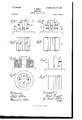
- Figure 1 is an end view of an open-end die with the lower end of the hammer embodying my invention.
- Fig. 2 is an end view of an open-end die with modified form of mounting the cheeks.
- Fig. 3 is a longitudinal section of Fig. 2.
- Fig. 4 is an end view of an open-end die for forging cylindrical articles.
- Fig. 5 illustrates a plan View of a die having inclosed ends.
- Figs. 6, 6 and 6 illustrate, respectively, a vertical cross-sectional View, a longitudinal View with one cheek removed, and a plan view of a die used for forming a desired article, as here the check of a vise with the necessary punch for forming a hole therein.
- Fig. 7 is an end view illustrating other modifications for mounting the cheeks.
- Figs. 8 and 8 are respectively end and plan views of an open-end die, illustratin g modifications in mounting the cheeks.
- Figs. 9 and 9 illustrate a die having cheeks mounted similarly to Figs. 8 and 8 with a diiferent-shaped die.
- Figs. 10 and 10 show an inclosed die respectively in cross-section and plan view.
- Figs. 11 and 11 represent in elevation and plan views another modified form of construction.
- the work-piece is illustrated as resting upon the bed-plate, Whereas in the remaining figures the die is formed out of the cheeks, with the exception of the upper surface, which is of course formed by the hammer. It will be clearly understood that after placing the metal lump in .position between the cheeks the hammer is dropped or a press-plunger is forced thereon, or any other pressure is brought to bear against the piece, whence the latter assumes the form of the die.
- I may employ checks (1 d, mounted on small arms h it, (see Fig. 7,) or, in place of either of these, sliding cheeks d 01*, moving against inclined faces formed in the inner sides of flanges c 0 as shown in Figs. 8, 8", 9*, and 9", in which case guide-cleats Z Z are formed or fastened on the ends of the flanges to prevent the lateral movement of the cheeks, or as another modification the die may be formed of a stationary flange d and a single cheek. (See Figscll and 11*.)
- a forging to be made require a closed die
- I may employ a plurality of rotatable checks, as shown in Fig. 5, or a plurality of sliding cheeks arranged pyramidically.
- the necessary die is formed in the cheeks, which may be rotatable, as shown in Figs. 6 to 6, inclusive, or may be sliding.
- Any necessary punches, 850. may be arranged on the hammer, as m, (see Figs. 6 and 6 with corresponding openings formed in the cheeks.
- a die is formed in which the cheeks are movable and ready access is to be had to the forging and in which the said checks are brought firmly into a cor-. rect position by the downward movement of the hammer.
- a bed-plate loosely and movably mounted cheeks supported on said bed-plate and a hammer mounted to frictionally directly engage the adjacent faces of said cheeks substantially as described.
- a bed-plate loosely and esaoe movably mounted cheeks having rounded tailpieces, and a hammer adapted to directly engage the adjacent faces of said checks, as set forth.
- a bed-plate Ina forge-die, a bed-plate, a plurality of cheeks arranged pyramidally with their adjacent faces relatively disposed to be frictionally directly engaged by a hammer, as and for-the purpose set forth.
- a bed-plate having par allel rounded grooves and inwardly-projecting flanges, and checks having rounded tailpieces loosely engaged in said groove and partiallybeneath said flanges for pivotal movement and having their adjacent faces relatively disposed andadapted to be frictionally engaged by a hammer, substantially as described.
Landscapes
- Engineering & Computer Science (AREA)
- Mechanical Engineering (AREA)
- Forging (AREA)
Description
no. 683,068. Patented Sept. 24, IBM.
K. PROTT. FORGE DIE.
- (Application filed. Dec. 22, 1900.)
2 Sheets-Sheet I.
(No Model.)
Invewlv 74 No. 683,068. Patented Sept. 24, l9'0l,
K. PRfiTT.
, FORGE ma.
, I (Application filed Due. 22, 1900.) (Np Modal.) 2 Sheets-Shoat 2.
' UNITED STATES PATENT ()FFICE.
KARL PRoTT, or HAGEN, GERMANY.
FORGE-DIE.
SPECIFICATION forming part of Letters Patent No. 683,068, dated September 24., 1901. Application filed Dec'e'inber 22, 1900. 'se'rin No. 40,742. on model.)
To all whom it may concern/.-
Be it known that I, KARL PRdTT, a subject of the German Emperor, and a resident of Hagen Westfallen, Germany, have invented a new and useful Forge-Die, of which the following is a specification.
My invention relates to frames or dies employed in forging metals by means of a haminer, &c.; and it consists of a frame having cheeks so arranged as to form a solid and substantial die or frame for the metal piece, but which checks can be easily raised, so that ready access may be had to said piece whether its sides are perpendicular or oblique.
In the accompanying drawings, in which similar letters refer throughout to similarparts, Figure 1 is an end view of an open-end die with the lower end of the hammer embodying my invention. Fig. 2 is an end view of an open-end die with modified form of mounting the cheeks. Fig. 3 is a longitudinal section of Fig. 2. Fig. 4 is an end view of an open-end die for forging cylindrical articles. Fig. 5 illustrates a plan View of a die having inclosed ends. Figs. 6, 6 and 6 illustrate, respectively, a vertical cross-sectional View, a longitudinal View with one cheek removed, and a plan view of a die used for forming a desired article, as here the check of a vise with the necessary punch for forming a hole therein. Fig. 7 is an end view illustrating other modifications for mounting the cheeks. Figs. 8 and 8 are respectively end and plan views of an open-end die, illustratin g modifications in mounting the cheeks. Figs. 9 and 9 illustrate a die having cheeks mounted similarly to Figs. 8 and 8 with a diiferent-shaped die. Figs. 10 and 10 show an inclosed die respectively in cross-section and plan view. Figs. 11 and 11 represent in elevation and plan views another modified form of construction.
As is well known in the art forged metal pieces having downwardly-converging sides can be easily removed from the die; but in the other instances, as where the piecehas parallel vertical sides or is circular in form or has upwardly-converging sides, the finished piece is difficult of access. In order, therefore, to eliminate this disadvantage, I have invented a die with movable cheeks. In
the construction thereof I employ a bed-plate a, which is provided with parallel grooves 11, Fig. 1, and upwardly and inwardly projecting flanges c. Cheeks d have rounded tailpieces e fitting into said grooves and partially beneath said flanges are mounted on said bed-plate and form between their adjacent faces the desired dies, in which the metal lump is placed and into which the head of the hammerf drops. For the purpose of clearly understanding the operation a work-piece of metal is shown in dotted lines in the several figures, with the head of the hammer thereagainst. In Fig. 1 the work-piece is illustrated as resting upon the bed-plate, Whereas in the remaining figures the die is formed out of the cheeks, with the exception of the upper surface, which is of course formed by the hammer. It will be clearly understood that after placing the metal lump in .position between the cheeks the hammer is dropped or a press-plunger is forced thereon, or any other pressure is brought to bear against the piece, whence the latter assumes the form of the die. The hammer in descending comes into frictional contact with the inner faces of the checks (1 aforesaid, which are thus pressed firmly down upon the bed-plate,forming thereby a solid and substantial die; but, however, when the said hammer is raised the cheeks can be easily swung about their points of pivott'. e., the said tailpieces resting in the said grooves-thus aifording ready access to the forging. In place, however, of forming grooves inthe bed-plate I'may simply form the said flanges as at c, (shown in Fig. 2,) while tailpieces e are correspondingly formed on the said-cheeks. In cases Where the bottom of the die is formed in the cheeks themselves, as illustrated in all the figures with the exception of Fig. 1, the adjacent contactingsurfaces are somewhat formed as illustrated at g g, Fig. 4. In place, however, of rotating checks, as shown in Figs. 1 to 6, inclusive,
I may employ checks (1 d, mounted on small arms h it, (see Fig. 7,) or, in place of either of these, sliding cheeks d 01*, moving against inclined faces formed in the inner sides of flanges c 0 as shown in Figs. 8, 8", 9*, and 9", in which case guide-cleats Z Z are formed or fastened on the ends of the flanges to prevent the lateral movement of the cheeks, or as another modification the die may be formed of a stationary flange d and a single cheek. (See Figscll and 11*.)
Whenever the forging to be made require a closed die, I may employ a plurality of rotatable checks, as shown in Fig. 5, or a plurality of sliding cheeks arranged pyramidically. In case it is desired to forge some particular article or design, as a vise-cheek, the necessary die is formed in the cheeks, which may be rotatable, as shown in Figs. 6 to 6, inclusive, or may be sliding. Any necessary punches, 850., may be arranged on the hammer, as m, (see Figs. 6 and 6 with corresponding openings formed in the cheeks. In all cases it will be seen that a die is formed in which the cheeks are movable and ready access is to be had to the forging and in which the said checks are brought firmly into a cor-. rect position by the downward movement of the hammer.
Having now described my invention, what I claim as new, and desire to protect by Letters Patent, is-
1. In a forge-die, a bed-plate, loosely and movably mounted cheeks supported on said bed-plate and a hammer mounted to frictionally directly engage the adjacent faces of said cheeks substantially as described.
2. In a forge-die, a bed-plate, loosely and esaoe movably mounted cheeks having rounded tailpieces, and a hammer adapted to directly engage the adjacent faces of said checks, as set forth.
3. In a forge-die, a bed-plate and a plurality of rotatable cheeks thereon having their adjacent faces relatively disposed to be engaged directly by a hammer, as set forth.
4. Ina forge-die, a bed-plate, a plurality of cheeks arranged pyramidally with their adjacent faces relatively disposed to be frictionally directly engaged by a hammer, as and for-the purpose set forth.
5. In a forge-die, a bed-plate having par allel rounded grooves and inwardly-projecting flanges, and checks having rounded tailpieces loosely engaged in said groove and partiallybeneath said flanges for pivotal movement and having their adjacent faces relatively disposed andadapted to be frictionally engaged by a hammer, substantially as described. i
In testimony whereof I have hereunto set my hand, this 10th day of September, 1900, in the presence of two witnesses.
p KARL PROT'I.
Witnesses:
OTTO KoNIG, HANS SCHADDE.
Priority Applications (1)
| Application Number | Priority Date | Filing Date | Title |
|---|---|---|---|
| US4074200A US683068A (en) | 1900-12-22 | 1900-12-22 | Forge-die. |
Applications Claiming Priority (1)
| Application Number | Priority Date | Filing Date | Title |
|---|---|---|---|
| US4074200A US683068A (en) | 1900-12-22 | 1900-12-22 | Forge-die. |
Publications (1)
| Publication Number | Publication Date |
|---|---|
| US683068A true US683068A (en) | 1901-09-24 |
Family
ID=2751611
Family Applications (1)
| Application Number | Title | Priority Date | Filing Date |
|---|---|---|---|
| US4074200A Expired - Lifetime US683068A (en) | 1900-12-22 | 1900-12-22 | Forge-die. |
Country Status (1)
| Country | Link |
|---|---|
| US (1) | US683068A (en) |
Cited By (1)
| Publication number | Priority date | Publication date | Assignee | Title |
|---|---|---|---|---|
| US2700906A (en) * | 1950-10-30 | 1955-02-01 | Cameron Iron Works Inc | Die holder |
-
1900
- 1900-12-22 US US4074200A patent/US683068A/en not_active Expired - Lifetime
Cited By (1)
| Publication number | Priority date | Publication date | Assignee | Title |
|---|---|---|---|---|
| US2700906A (en) * | 1950-10-30 | 1955-02-01 | Cameron Iron Works Inc | Die holder |
Similar Documents
| Publication | Publication Date | Title |
|---|---|---|
| US683068A (en) | Forge-die. | |
| US3595011A (en) | Method of forming chain side bars with curved bearing surfaces | |
| US839839A (en) | Apparatus for forming sheet-metal hanger-legs. | |
| US279118A (en) | allen | |
| US516180A (en) | Herman v | |
| US562309A (en) | Worth | |
| US397786A (en) | Die for the manufacture of lids for journal-boxes | |
| US1142419A (en) | Apparatus for manufacture of car and similar wheels. | |
| US6477883B2 (en) | Die block apparatus for shaping workpieces | |
| US1007942A (en) | Apparatus for the manufacture of car-wheels. | |
| US1148245A (en) | Nail, spike, and the like with soft-metal head. | |
| US28565A (en) | Machine eoe making tabs foe ckossctjt-saws | |
| US42907A (en) | Improvement in stamping | |
| US651748A (en) | Spiral-die. | |
| US949807A (en) | Press. | |
| US66436A (en) | Lorenz wolf | |
| US104931A (en) | Improved machine for forging the heads of wrenches | |
| US55944A (en) | Improvement in dies for cupping and raising articles of metal | |
| US438112A (en) | William mitchell | |
| US58040A (en) | Improvement in making bolts | |
| US487730A (en) | Stamping-press | |
| US471148A (en) | Island | |
| US406552A (en) | Apparatus for upsetting eye-bars | |
| US123079A (en) | Improvement in the manufacture of carriage-spring clips | |
| US1522149A (en) | Apparatus for truing brake drums |