US6830426B1 - Gas injection seal system for a centrifugal pump - Google Patents
Gas injection seal system for a centrifugal pump Download PDFInfo
- Publication number
- US6830426B1 US6830426B1 US10/193,841 US19384102A US6830426B1 US 6830426 B1 US6830426 B1 US 6830426B1 US 19384102 A US19384102 A US 19384102A US 6830426 B1 US6830426 B1 US 6830426B1
- Authority
- US
- United States
- Prior art keywords
- impeller
- centrifugal pump
- grooves
- seal
- tip ring
- Prior art date
- Legal status (The legal status is an assumption and is not a legal conclusion. Google has not performed a legal analysis and makes no representation as to the accuracy of the status listed.)
- Expired - Fee Related, expires
Links
- 238000002347 injection Methods 0.000 title claims description 16
- 239000007924 injection Substances 0.000 title claims description 16
- 239000012530 fluid Substances 0.000 claims abstract description 15
- 230000013011 mating Effects 0.000 claims description 3
- 238000000034 method Methods 0.000 claims 1
- 238000007789 sealing Methods 0.000 description 2
- 230000008030 elimination Effects 0.000 description 1
- 238000003379 elimination reaction Methods 0.000 description 1
- 230000030400 head development Effects 0.000 description 1
- 230000002706 hydrostatic effect Effects 0.000 description 1
- 238000012827 research and development Methods 0.000 description 1
- 238000010008 shearing Methods 0.000 description 1
Images


Classifications
-
- F—MECHANICAL ENGINEERING; LIGHTING; HEATING; WEAPONS; BLASTING
- F04—POSITIVE - DISPLACEMENT MACHINES FOR LIQUIDS; PUMPS FOR LIQUIDS OR ELASTIC FLUIDS
- F04D—NON-POSITIVE-DISPLACEMENT PUMPS
- F04D29/00—Details, component parts, or accessories
- F04D29/08—Sealings
- F04D29/10—Shaft sealings
- F04D29/12—Shaft sealings using sealing-rings
- F04D29/126—Shaft sealings using sealing-rings especially adapted for liquid pumps
- F04D29/128—Shaft sealings using sealing-rings especially adapted for liquid pumps with special means for adducting cooling or sealing fluid
-
- F—MECHANICAL ENGINEERING; LIGHTING; HEATING; WEAPONS; BLASTING
- F04—POSITIVE - DISPLACEMENT MACHINES FOR LIQUIDS; PUMPS FOR LIQUIDS OR ELASTIC FLUIDS
- F04D—NON-POSITIVE-DISPLACEMENT PUMPS
- F04D29/00—Details, component parts, or accessories
- F04D29/08—Sealings
- F04D29/16—Sealings between pressure and suction sides
- F04D29/165—Sealings between pressure and suction sides especially adapted for liquid pumps
- F04D29/167—Sealings between pressure and suction sides especially adapted for liquid pumps of a centrifugal flow wheel
Definitions
- This invention relates to gas injection seal systems for centrifugal pumps and particularly to centrifugal pumps disk friction reducing injection rings and eye ring seals.
- centrifugal pumps with closed impellers have a cavity between the impeller and the pump casing.
- a small radial gap exists at the eye of the impeller between the rotating impeller and the stationary casing, which is called the wear ring gap.
- the designs allow fluid at discharge pressure from the impeller to circulate behind the impeller shroud in the cavity between the shroud and the casing. It also allows a certain quantity of fluid to leak back to the suction side of the impeller through the wear ring gap.
- the fluid behind the impeller creates a power loss due to the shearing of the fluid between the impeller shroud and the casing wall.
- the wear ring leakage also creates a power loss because the leaking fluid loses all of the energy that the impeller imparted to it and then is reintroduced to the suction stream to be pumped again.
- a set of seals is installed on the impeller that allows a low viscosity fluid (typically gas) to be injected into a chamber between the impeller shroud and the casing sidewall at a pressure higher than suction pressure.
- a low viscosity fluid typically gas
- each impeller shroud there is a seal ring installed on the tip of the impeller's outer perimeter. Another seal ring is mounted at the leading edge of the eye of the impeller.
- the seals installed on the tip of the impeller (tip seals) have a series of grooves formed in them that are open to the chamber on the backside of the impeller shroud.
- a gas is injected through a port in the case and into a chamber formed by the tip seal, the eye ring seal, the impeller shroud and the casing wall. The gas is then picked up by the grooves in the impeller tip seal ring inside diameter and is compressed by centrifugal force to a higher pressure than the discharge pressure of the impeller. It is then injected into the pumpage stream.
- the eye ring seals have pockets and inject gas at a low volume into the eye of the impeller. In this way, both leakage problems described above can be eliminated.
- the disk friction reducing injection mechanism drastically reduces the losses associated with disk friction and wear ring leakage losses. This combination increase pump efficiencies.
- This invention can work on a variety of centrifugal pump types including double suction impellers; single suction closed impellers and open face impellers with a single shroud.
- FIG. 1 is a partial exploded view of the disk friction reducing injection system.
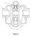
- FIG. 2 is a cross-sectional view of the invention.
- FIG. 3 is an inset of the invention as shown in cross-section of FIG. 2 .
- FIG. 4 is a detail cross-sectional view of the invention showing gas ports and the chambers formed by the seals.
- FIG. 5 is a perspective view of a tip ring showing one style of groove pattern.
- FIG. 5 a is an enlarged view of one of the radial tapered trapezoid grooves in the top ring of FIG. 5 .
- FIG. 6 is a perspective view of a second tip ring showing a second groove pattern.
- FIG. 7 is an enlarged detail view of a portion of the tip ring of FIG. 6 .
- FIG. 8 a is a front view of a tip ring having a third groove pattern with a first profile.
- FIG. 8 b is a front view of a tip ring having the third groove pattern with a second profile.
- FIG. 9 is a cross-sectional view taken along the lines 9 — 9 of FIG. 8 a of one of the grooves of FIG. 8 a showing the pattern as being rectangular.
- FIG. 10 is a cross-sectional view taken along the lines 10 — 10 of FIG. 8 b of one of the grooves of FIG. 8 b showing the pattern as being angled.
- the invention is a centrifugal pump 1 that has an outer casing 2 .
- an impeller 3 that has two disk shrouds 4 that enclose the vanes 5 .
- Two seal rings 6 also called tip seal rings
- the chambers 7 are used in part to inject gas into the pump, as discussed below.
- a two-part mating seal ring 8 a and 8 b is mounted to the case 2 for each tip ring seal.
- the compliant structure includes a spring 9 . See FIG. 3 .
- other similar structures may also be used.
- a tip seal ring 6 that has a number of grooves 11 that allow a gas to be compressed due to the centrifugal force is installed on the tip of the impeller.
- the gas is discussed in more detail below.
- the groove depth flow area at the inner diameter of the ring is significantly greater than the discharge area of the seal allowing for full head development. For example, for a seal discharge area of 0.068 in 2 (0.439 cm 2 ), the groove depth flow area at the inner diameter of the ring is typically between 0.204 in 2 (1.31 cm 2 ) and 0.272 in 2 (1.75 cm 2 ).
- the preferred grooving is a radial tapered trapezoid that extends from a narrow throat at the inside diameter to a broad shallow structure at a diameter that is not greater than the outside diameter creating sealing dam. See FIG. 5 a . These grooves allow the gas on the chamber side of the impeller to be injected into the discharge stream of the impeller.
- FIG. 5 shows a tip ring 30 having a number of radial tapered grooves 31 . See also FIG. 5 a.
- FIG. 6 shows the seal ring 40 having a number of recessed pockets 41 . Within each pocket is an injection port 42 . This structure creates a hydrostatic force in the pocket and allows for a gas seal.
- multiple pockets 41 can be arranged around the diameter of the ring 40 and an external gas source is brought directly to an annular groove 44 that distributes the gas to all of the pockets.
- the small diameter hole 42 connects each pocket with the annular groove. The pressurized gas is then injected between the faces to create a seal.
- the design can either be on a face, taper or annular design.
- the grooving pattern for both the disk injection seal and the eye ring seal also can be a spiral groove pattern.
- FIG. 8 a shows a tip ring 50 with spiral grooves 51 .
- FIG. 9 shows these grooves have a generally rectangular cross-section.
- FIG. 8 b shows the tip ring 50 with radial tapered grooves 52 .
- FIG. 10 shows these grooves 52 to be angled.
- the seals (also called eye rings) consist of a smooth ring 10 mounted on the impeller eye, and a mating ring 12 consisting of recessed pockets 13 , is also to the case as shown in FIG. 1 .
- FIG. 4 shows the gas handling structure.
- the pockets (or grooves) in the tip rings are set to control the amount of gas injected.
- the chambers 7 formed by the eye ring seal and the tip injection seal are ported to an external source of pressurized fluid.
- the ports 25 carry the gas to the chambers 7 as shown in FIG. 4 . In this way, the chamber pressure on the opposing sides of the impeller shrouds controls the impeller thrust.
- the efficiency of the pump can be increased by drastically reducing the disk friction and the normal fluid leakage loss that flows around the back side of the impeller and through the small gap at the impeller eye.
- seal rings described above can be used for abrasive service pumps to inject a clean fluid into the discharge stream reducing the amount of exposed surface to wear.
- seal rings can be utilized as a bearing system for the pump.
- the pressure produced by a radial or taper groove design is sufficient to support the rotor weight and seal the chamber. This allows for the elimination of external bearings.
- the disk injection ring 6 at the tip of the impeller has multiple grooves 11 with each groove throat open to the chamber 7 that has the pressurized gas.
- the motion of the injection ring as it rotates with the impeller imparts a centrifugal force to the gas and compresses it proportional to the head generation of the impeller.
- the gas pressure in the chamber is significant enough to allow the added head of the injection ring to inject a small quantity of gas into the discharge stream.
- the eye seal ring pockets are pressurized to allow for a controlled amount of gas to flow between the seal faces and be injected into the suction fluid.
Landscapes
- Engineering & Computer Science (AREA)
- Mechanical Engineering (AREA)
- General Engineering & Computer Science (AREA)
- Structures Of Non-Positive Displacement Pumps (AREA)
Abstract
A set of seals is installed on the impeller of a centrifugal pump that allows a low viscosity fluid to be injected into a chamber between the impeller shroud and the casing sidewall. A seal ring, with a number of grooves formed in it is installed on the tip of the impeller. Another seal ring is mounted at the leading edge of the eye of the impeller. The gas is picked up by the grooves in the impeller tip ring inside diameter and is compressed by centrifugal force to a higher pressure than the discharge pressure of the impeller. It is then injected into the pumpage stream. The eye ring seals have pockets or grooves and inject gas at a low volume into the eye of the impeller.
Description
Not Applicable
Not Applicable
1. Field of the Invention
This invention relates to gas injection seal systems for centrifugal pumps and particularly to centrifugal pumps disk friction reducing injection rings and eye ring seals.
2. Description of the Prior Art
In the prior art, centrifugal pumps with closed impellers (i.e., those with shrouds on both sides of the vanes) have a cavity between the impeller and the pump casing. Also, a small radial gap exists at the eye of the impeller between the rotating impeller and the stationary casing, which is called the wear ring gap. The designs allow fluid at discharge pressure from the impeller to circulate behind the impeller shroud in the cavity between the shroud and the casing. It also allows a certain quantity of fluid to leak back to the suction side of the impeller through the wear ring gap. As the impeller rotates, the fluid behind the impeller creates a power loss due to the shearing of the fluid between the impeller shroud and the casing wall. The wear ring leakage also creates a power loss because the leaking fluid loses all of the energy that the impeller imparted to it and then is reintroduced to the suction stream to be pumped again.
The instant invention overcomes all of these problems. In the instant design, a set of seals is installed on the impeller that allows a low viscosity fluid (typically gas) to be injected into a chamber between the impeller shroud and the casing sidewall at a pressure higher than suction pressure.
On each impeller shroud there is a seal ring installed on the tip of the impeller's outer perimeter. Another seal ring is mounted at the leading edge of the eye of the impeller. The seals installed on the tip of the impeller (tip seals) have a series of grooves formed in them that are open to the chamber on the backside of the impeller shroud. A gas is injected through a port in the case and into a chamber formed by the tip seal, the eye ring seal, the impeller shroud and the casing wall. The gas is then picked up by the grooves in the impeller tip seal ring inside diameter and is compressed by centrifugal force to a higher pressure than the discharge pressure of the impeller. It is then injected into the pumpage stream. The eye ring seals have pockets and inject gas at a low volume into the eye of the impeller. In this way, both leakage problems described above can be eliminated. The disk friction reducing injection mechanism drastically reduces the losses associated with disk friction and wear ring leakage losses. This combination increase pump efficiencies.
This invention can work on a variety of centrifugal pump types including double suction impellers; single suction closed impellers and open face impellers with a single shroud.
FIG. 1 is a partial exploded view of the disk friction reducing injection system.
FIG. 2 is a cross-sectional view of the invention.
FIG. 3 is an inset of the invention as shown in cross-section of FIG. 2.
FIG. 4 is a detail cross-sectional view of the invention showing gas ports and the chambers formed by the seals.
FIG. 5 is a perspective view of a tip ring showing one style of groove pattern.
FIG. 5a is an enlarged view of one of the radial tapered trapezoid grooves in the top ring of FIG. 5.
FIG. 6 is a perspective view of a second tip ring showing a second groove pattern.
FIG. 7 is an enlarged detail view of a portion of the tip ring of FIG. 6.
FIG. 8a is a front view of a tip ring having a third groove pattern with a first profile.
FIG. 8b is a front view of a tip ring having the third groove pattern with a second profile.
FIG. 9 is a cross-sectional view taken along the lines 9—9 of FIG. 8a of one of the grooves of FIG. 8a showing the pattern as being rectangular.
FIG. 10 is a cross-sectional view taken along the lines 10—10 of FIG. 8b of one of the grooves of FIG. 8b showing the pattern as being angled.
Referring new to FIGS. 1, 2 and 3 the invention is a centrifugal pump 1 that has an outer casing 2. Within the outer casing there is an impeller 3 that has two disk shrouds 4 that enclose the vanes 5. Two seal rings 6 (also called tip seal rings) are mounted to the impeller disk shrouds at the tip of the outer diameter of the impeller 3 to prevent fluid from leaking from the impeller 3 into the chamber 7 between the shroud disks 4 and the casing 2. (See FIG. 4). The chambers 7 are used in part to inject gas into the pump, as discussed below.
A two-part mating seal ring 8 a and 8 b is mounted to the case 2 for each tip ring seal. In the preferred embodiment, the compliant structure includes a spring 9. See FIG. 3. However, other similar structures may also be used.
A tip seal ring 6 that has a number of grooves 11 that allow a gas to be compressed due to the centrifugal force is installed on the tip of the impeller. The gas is discussed in more detail below. The groove depth flow area at the inner diameter of the ring is significantly greater than the discharge area of the seal allowing for full head development. For example, for a seal discharge area of 0.068 in2 (0.439 cm2), the groove depth flow area at the inner diameter of the ring is typically between 0.204 in2 (1.31 cm2) and 0.272 in2 (1.75 cm2).
The preferred grooving is a radial tapered trapezoid that extends from a narrow throat at the inside diameter to a broad shallow structure at a diameter that is not greater than the outside diameter creating sealing dam. See FIG. 5a. These grooves allow the gas on the chamber side of the impeller to be injected into the discharge stream of the impeller. FIG. 5 shows a tip ring 30 having a number of radial tapered grooves 31. See also FIG. 5a.
Moreover, instead of tapered grooves for the seal rings, recessed pockets can be utilized and gas can be directly injected into the pocket. These are shown in FIGS. 6 and 7. FIG. 6 shows the seal ring 40 having a number of recessed pockets 41. Within each pocket is an injection port 42. This structure creates a hydrostatic force in the pocket and allows for a gas seal. In one embodiment, multiple pockets 41 can be arranged around the diameter of the ring 40 and an external gas source is brought directly to an annular groove 44 that distributes the gas to all of the pockets. The small diameter hole 42 connects each pocket with the annular groove. The pressurized gas is then injected between the faces to create a seal. The design can either be on a face, taper or annular design.
As shown in FIGS. 8a-10, the grooving pattern for both the disk injection seal and the eye ring seal also can be a spiral groove pattern. FIG. 8a shows a tip ring 50 with spiral grooves 51. FIG. 9 shows these grooves have a generally rectangular cross-section. FIG. 8b shows the tip ring 50 with radial tapered grooves 52. FIG. 10 shows these grooves 52 to be angled.
Referring now to FIG. 1, two seals are mounted at the eye of the impeller to prevent excessive gas flow into the suction of the impeller. The seals (also called eye rings) consist of a smooth ring 10 mounted on the impeller eye, and a mating ring 12 consisting of recessed pockets 13, is also to the case as shown in FIG. 1.
The injected gas mentioned above has sufficient pressure to inject itself into the eye of the impeller, i.e.; its pressure is greater than the pump head developed by the pump. FIG. 4 shows the gas handling structure. As discussed above, the pockets (or grooves) in the tip rings are set to control the amount of gas injected. The chambers 7 formed by the eye ring seal and the tip injection seal are ported to an external source of pressurized fluid. The ports 25 carry the gas to the chambers 7 as shown in FIG. 4. In this way, the chamber pressure on the opposing sides of the impeller shrouds controls the impeller thrust.
Thus, by injecting a low viscosity fluid on the back side of the impeller and sealing the chamber at the eye side of the impeller, the efficiency of the pump can be increased by drastically reducing the disk friction and the normal fluid leakage loss that flows around the back side of the impeller and through the small gap at the impeller eye.
Note that the above design can work also with open-faced impellers with only one shroud. In this design only the impeller tip seal ring is used.
Note also that the seal rings described above can be used for abrasive service pumps to inject a clean fluid into the discharge stream reducing the amount of exposed surface to wear.
Finally, the seal rings can be utilized as a bearing system for the pump. The pressure produced by a radial or taper groove design is sufficient to support the rotor weight and seal the chamber. This allows for the elimination of external bearings.
Description of Operation
As discussed above, the disk injection ring 6 at the tip of the impeller has multiple grooves 11 with each groove throat open to the chamber 7 that has the pressurized gas. The motion of the injection ring as it rotates with the impeller imparts a centrifugal force to the gas and compresses it proportional to the head generation of the impeller. The gas pressure in the chamber is significant enough to allow the added head of the injection ring to inject a small quantity of gas into the discharge stream. The eye seal ring pockets are pressurized to allow for a controlled amount of gas to flow between the seal faces and be injected into the suction fluid.
The net result is that disk friction is significantly reduced, producing a more efficient centrifugal pump.
The present disclosure should not be construed in any limited sense other than that limited by the scope of the claims having regard to the teachings herein and the prior art being apparent with the preferred form of the invention disclosed herein and which reveals details of structure of a preferred form necessary for a better understanding of the invention and may be subject to change by skilled persons within the scope of the invention without departing from the concept thereof.
Claims (18)
1. In a centrifugal pump having a case, an impeller, and an impeller shroud, a disk fiction reducing system comprising:
a) at least one tip ring seal in fluid communication with said impeller; and
b) a means for injecting a gas into said impeller through said tip ring seal, said means for injecting including a means for pressurizing said gas whereby said gas is at a pressure higher than a discharge pressure of the centrifugal pump;
c) wherein said at least one tip ring seal comprises a plurality of recessed pockets formed about said tip ring seal, and a port formed in each of said plurality of recessed pockets through which a low viscosity fluid may be directly injected.
2. The centrifugal pump according to claim 1 further comprising a mating seal having a compliant structure.
3. The centrifugal pump according to claim 2 wherein the compliant structure includes a spring.
4. The centrifugal pump according to claim 1 wherein the tip ring seal has a plurality of grooves formed thereon.
5. The centrifugal pump according to claim 4 wherein the plurality of grooves has a radial design.
6. The centrifugal pump according to claim 4 wherein the plurality of grooves has a tapered design.
7. The centrifugal pump according to claim 4 wherein the plurality of grooves has a recessed design.
8. The centrifugal pump according to claim 1 , wherein the tip ring seal can be utilized as a bearing for the centrifugal pump.
9. A seal ring system for a centrifugal pump having an impeller having a first side and a second side, an impeller shroud and a housing, comprising:
a) a first eye seal sealably attached to the first side of said impeller;
b) a first tip ring, in operable contact with the first side of said impeller, wherein the first tip ring having a plurality of grooves formed therein;
c) a second eye seal sealably attached to the second side of said impeller;
d) a second tip ring, in operable contact with the second side of said impeller, wherein the second tip ring having a plurality of grooves formed therein;
e) a gas injection port, in communication with said plurality of grooves in said first tip ring; and
f) a gas injection port, in communication with said plurality of grooves in said second tip ring.
10. The seal ring system for a centrifugal pump of claim 9 wherein the second eye seal further has plurality of grooves formed therein.
11. The centrifugal pump according to claim 9 wherein the plurality of grooves has a radial design.
12. The centrifugal pump according to claim 9 wherein the plurality of grooves has a tapered design.
13. The centrifugal pump according to claim 9 wherein the plurality of grooves has a recessed design.
14. A seal ring system for a centrifugal pump having an impeller having a first side and a second side, an impeller shroud and a housing, comprises:
a) a first eye seal sealably attached to the first side of said impeller;
b) a first tip ring, in operable contact with the first side of said impeller, said first tip ring having a plurality of grooves;
c) a second eye seal sealably attached to the second side of said impeller;
d) a second tip ring, in operable contact with the second side of said impeller,
wherein the second tip ring having a plurality of grooves formed therein;
e) a first chamber formed in said housing and bounded by the first tip ring, the first eye seal, the impeller shroud and a wall of said housing;
f) a second chamber formed in said housing and bounded by the second tip ring, the second eye seal, the impeller shroud and a wall of said housing;
e) a first gas injection port, in communication with first chamber; and
f) a second gas port in communication with said second chamber.
15. The centrifugal pump according to claim 14 wherein the plurality of grooves in said first and second tip rings have a radial design.
16. The centrifugal pump according to claim 14 , wherein the plurality of grooves in said first and second tip rings have a tapered design.
17. The centrifugal pump according to claim 14 wherein the plurality of grooves in said first and second tip rings have a recessed design.
18. A method of reducing disk friction in a centrifugal pump having a housing, a first eye seal sealably attached to a first side of an impeller, a first tip ring, in operable contact with the first side of said impeller, said first tip ring having a plurality of grooves, a second eye seal sealably attached to a second side of said impeller, a second tip ring in operable contact with the second side of said impeller, wherein the second tip ring, having a plurality of grooves formed therein, a first chamber formed in said housing and bounded by the first tip ring, the first eye seal, the impeller shroud and a wall of said housing; a second chamber formed in said housing and bounded by the second tip ring, the second eye seal, the impeller shroud and a wall of said housing; a first gas injection port, in communication with said first chamber, and a second gas port in communication with said second chamber, comprising the steps of:
a) injecting a quantity of gas into said first and second gas injection ports;
b) moving said quantity of gas into said first and second chambers;
c) forcing said quantity of gas into the plurality of grooves on said first and second tip rings; and
d) accelerating said quantity of gas, thereby pressurizing said quantity of gas to a pressure greater than a head pressure generated by said centrifugal pump.
Priority Applications (1)
| Application Number | Priority Date | Filing Date | Title |
|---|---|---|---|
| US10/193,841 US6830426B1 (en) | 2002-07-11 | 2002-07-11 | Gas injection seal system for a centrifugal pump |
Applications Claiming Priority (1)
| Application Number | Priority Date | Filing Date | Title |
|---|---|---|---|
| US10/193,841 US6830426B1 (en) | 2002-07-11 | 2002-07-11 | Gas injection seal system for a centrifugal pump |
Publications (1)
| Publication Number | Publication Date |
|---|---|
| US6830426B1 true US6830426B1 (en) | 2004-12-14 |
Family
ID=33489012
Family Applications (1)
| Application Number | Title | Priority Date | Filing Date |
|---|---|---|---|
| US10/193,841 Expired - Fee Related US6830426B1 (en) | 2002-07-11 | 2002-07-11 | Gas injection seal system for a centrifugal pump |
Country Status (1)
| Country | Link |
|---|---|
| US (1) | US6830426B1 (en) |
Cited By (1)
| Publication number | Priority date | Publication date | Assignee | Title |
|---|---|---|---|---|
| US20140054863A1 (en) * | 2012-08-21 | 2014-02-27 | General Electric Company | Seal assembly for a turbine system |
Citations (9)
| Publication number | Priority date | Publication date | Assignee | Title |
|---|---|---|---|---|
| US794185A (en) * | 1904-07-21 | 1905-07-11 | Laval Steam Turbine Co | Wearing-ring for centrifugal pumps. |
| US835836A (en) * | 1906-02-27 | 1906-11-13 | Richard Schulz | Labyrinth packing for rotary machines. |
| US1820150A (en) * | 1920-09-15 | 1931-08-25 | Moody Lewis Ferry | Labyrinth packing for turbines |
| US2013499A (en) * | 1932-08-29 | 1935-09-03 | Pettibone Mulliken Company | Sealing means |
| US2604050A (en) * | 1948-04-27 | 1952-07-22 | Standard Oil Dev Co | Centrifugal pump impeller seal ring |
| GB932632A (en) * | 1960-08-23 | 1963-07-31 | Dominion Eng Works Ltd | Improvements in or relating to hydraulic turbines |
| US3245656A (en) * | 1964-04-06 | 1966-04-12 | Dominion Eng Works Ltd | Automatic supply of sealing fluid for rotary fluid machines |
| US3797962A (en) * | 1971-01-27 | 1974-03-19 | Stahlecker Gmbh Wilhelm | Spinning turbine |
| US5297928A (en) * | 1992-06-15 | 1994-03-29 | Mitsubishi Jukogyo Kabushiki Kaisha | Centrifugal compressor |
-
2002
- 2002-07-11 US US10/193,841 patent/US6830426B1/en not_active Expired - Fee Related
Patent Citations (9)
| Publication number | Priority date | Publication date | Assignee | Title |
|---|---|---|---|---|
| US794185A (en) * | 1904-07-21 | 1905-07-11 | Laval Steam Turbine Co | Wearing-ring for centrifugal pumps. |
| US835836A (en) * | 1906-02-27 | 1906-11-13 | Richard Schulz | Labyrinth packing for rotary machines. |
| US1820150A (en) * | 1920-09-15 | 1931-08-25 | Moody Lewis Ferry | Labyrinth packing for turbines |
| US2013499A (en) * | 1932-08-29 | 1935-09-03 | Pettibone Mulliken Company | Sealing means |
| US2604050A (en) * | 1948-04-27 | 1952-07-22 | Standard Oil Dev Co | Centrifugal pump impeller seal ring |
| GB932632A (en) * | 1960-08-23 | 1963-07-31 | Dominion Eng Works Ltd | Improvements in or relating to hydraulic turbines |
| US3245656A (en) * | 1964-04-06 | 1966-04-12 | Dominion Eng Works Ltd | Automatic supply of sealing fluid for rotary fluid machines |
| US3797962A (en) * | 1971-01-27 | 1974-03-19 | Stahlecker Gmbh Wilhelm | Spinning turbine |
| US5297928A (en) * | 1992-06-15 | 1994-03-29 | Mitsubishi Jukogyo Kabushiki Kaisha | Centrifugal compressor |
Cited By (1)
| Publication number | Priority date | Publication date | Assignee | Title |
|---|---|---|---|---|
| US20140054863A1 (en) * | 2012-08-21 | 2014-02-27 | General Electric Company | Seal assembly for a turbine system |
Similar Documents
| Publication | Publication Date | Title |
|---|---|---|
| US8337142B2 (en) | System and method for reducing thrust acting on submersible pumping components | |
| US5340272A (en) | Multi-stage centrifugal pump incorporating a sealed thrust bearing | |
| US4613281A (en) | Hydrodynamic seal | |
| EP1065383A1 (en) | Sealless integral-motor pump with regenerative impeller disc | |
| DK1451472T3 (en) | Improved pressure bearing for multistage centrifugal pumps | |
| US20070280823A1 (en) | Seal device for a fluid machine | |
| WO1994004827A9 (en) | Multi-stage centrifugal pump incorporating a sealed thrust bearing | |
| US20050047904A1 (en) | Vacuum pump | |
| KR20220090364A (en) | Compressor | |
| US6830426B1 (en) | Gas injection seal system for a centrifugal pump | |
| EP0551435B1 (en) | Integrated centrifugal pump and motor | |
| US9004857B2 (en) | Barrel-shaped centrifugal compressor | |
| CN102713302B (en) | submersible pump stage | |
| RU2263809C2 (en) | Multistage gas turbine | |
| US7931278B2 (en) | Seal assembly for a rotary member | |
| CN101649839A (en) | Deep-well centrifugal pump with two thrust bearing pairs on each impeller | |
| KR102702678B1 (en) | Regenerative blower-compressor with shaft bypass fluid re-vents | |
| CN1439808A (en) | Multistage sectional centrifugal pump with symmetric impeller arrangement | |
| JP2006183465A (en) | Centrifugal compressor | |
| KR100917250B1 (en) | Turbomachinery with bellows for automatic axial thrust | |
| CN207229398U (en) | Pump turbine structure | |
| CN114069936A (en) | Double thrust submersible motor | |
| US3635582A (en) | Seals for hydraulic machines | |
| CN114483633A (en) | Leakage amount controllable centrifugal pump axial force balance structure | |
| JPH085358Y2 (en) | Gas seal type motor pump device |
Legal Events
| Date | Code | Title | Description |
|---|---|---|---|
| REMI | Maintenance fee reminder mailed | ||
| LAPS | Lapse for failure to pay maintenance fees | ||
| STCH | Information on status: patent discontinuation |
Free format text: PATENT EXPIRED DUE TO NONPAYMENT OF MAINTENANCE FEES UNDER 37 CFR 1.362 |
|
| FP | Lapsed due to failure to pay maintenance fee |
Effective date: 20081214 |