US6830278B2 - Vehicle occupant protection apparatus - Google Patents

Vehicle occupant protection apparatus Download PDF

Info

Publication number
US6830278B2
US6830278B2 US10/439,042 US43904203A US6830278B2 US 6830278 B2 US6830278 B2 US 6830278B2 US 43904203 A US43904203 A US 43904203A US 6830278 B2 US6830278 B2 US 6830278B2
Authority
US
United States
Prior art keywords
headrest
vehicle
advance
impact
actuating mechanism
Prior art date
Legal status (The legal status is an assumption and is not a legal conclusion. Google has not performed a legal analysis and makes no representation as to the accuracy of the status listed.)
Expired - Fee Related
Application number
US10/439,042
Other versions
US20030227199A1 (en
Inventor
Ryozo Yoshizawa
Isamu Nakanishi
Current Assignee (The listed assignees may be inaccurate. Google has not performed a legal analysis and makes no representation or warranty as to the accuracy of the list.)
Honda Motor Co Ltd
Original Assignee
Honda Motor Co Ltd
Priority date (The priority date is an assumption and is not a legal conclusion. Google has not performed a legal analysis and makes no representation as to the accuracy of the date listed.)
Filing date
Publication date
Application filed by Honda Motor Co Ltd filed Critical Honda Motor Co Ltd
Assigned to HONDA GIKEN KOGYO KABUSHIKI KAISHA reassignment HONDA GIKEN KOGYO KABUSHIKI KAISHA ASSIGNMENT OF ASSIGNORS INTEREST (SEE DOCUMENT FOR DETAILS). Assignors: NAKANISHI, ISAMU, YOSHIZAWA, RYOZO
Publication of US20030227199A1 publication Critical patent/US20030227199A1/en
Application granted granted Critical
Publication of US6830278B2 publication Critical patent/US6830278B2/en
Anticipated expiration legal-status Critical
Expired - Fee Related legal-status Critical Current

Links

Images

Classifications

    • BPERFORMING OPERATIONS; TRANSPORTING
    • B60VEHICLES IN GENERAL
    • B60RVEHICLES, VEHICLE FITTINGS, OR VEHICLE PARTS, NOT OTHERWISE PROVIDED FOR
    • B60R21/00Arrangements or fittings on vehicles for protecting or preventing injuries to occupants or pedestrians in case of accidents or other traffic risks
    • B60R21/01Electrical circuits for triggering passive safety arrangements, e.g. airbags, safety belt tighteners, in case of vehicle accidents or impending vehicle accidents
    • B60R21/013Electrical circuits for triggering passive safety arrangements, e.g. airbags, safety belt tighteners, in case of vehicle accidents or impending vehicle accidents including means for detecting collisions, impending collisions or roll-over
    • BPERFORMING OPERATIONS; TRANSPORTING
    • B60VEHICLES IN GENERAL
    • B60NSEATS SPECIALLY ADAPTED FOR VEHICLES; VEHICLE PASSENGER ACCOMMODATION NOT OTHERWISE PROVIDED FOR
    • B60N2/00Seats specially adapted for vehicles; Arrangement or mounting of seats in vehicles
    • B60N2/24Seats specially adapted for vehicles; Arrangement or mounting of seats in vehicles for particular purposes or particular vehicles
    • B60N2/42Seats specially adapted for vehicles; Arrangement or mounting of seats in vehicles for particular purposes or particular vehicles the seat constructed to protect the occupant from the effect of abnormal g-forces, e.g. crash or safety seats
    • B60N2/4207Seats specially adapted for vehicles; Arrangement or mounting of seats in vehicles for particular purposes or particular vehicles the seat constructed to protect the occupant from the effect of abnormal g-forces, e.g. crash or safety seats characterised by the direction of the g-forces
    • B60N2/4214Seats specially adapted for vehicles; Arrangement or mounting of seats in vehicles for particular purposes or particular vehicles the seat constructed to protect the occupant from the effect of abnormal g-forces, e.g. crash or safety seats characterised by the direction of the g-forces longitudinal
    • B60N2/4228Seats specially adapted for vehicles; Arrangement or mounting of seats in vehicles for particular purposes or particular vehicles the seat constructed to protect the occupant from the effect of abnormal g-forces, e.g. crash or safety seats characterised by the direction of the g-forces longitudinal due to impact coming from the rear
    • BPERFORMING OPERATIONS; TRANSPORTING
    • B60VEHICLES IN GENERAL
    • B60NSEATS SPECIALLY ADAPTED FOR VEHICLES; VEHICLE PASSENGER ACCOMMODATION NOT OTHERWISE PROVIDED FOR
    • B60N2/00Seats specially adapted for vehicles; Arrangement or mounting of seats in vehicles
    • B60N2/24Seats specially adapted for vehicles; Arrangement or mounting of seats in vehicles for particular purposes or particular vehicles
    • B60N2/42Seats specially adapted for vehicles; Arrangement or mounting of seats in vehicles for particular purposes or particular vehicles the seat constructed to protect the occupant from the effect of abnormal g-forces, e.g. crash or safety seats
    • B60N2/427Seats or parts thereof displaced during a crash
    • B60N2/42772Seats or parts thereof displaced during a crash characterised by the triggering system
    • B60N2/4279Seats or parts thereof displaced during a crash characterised by the triggering system electric or electronic triggering
    • BPERFORMING OPERATIONS; TRANSPORTING
    • B60VEHICLES IN GENERAL
    • B60NSEATS SPECIALLY ADAPTED FOR VEHICLES; VEHICLE PASSENGER ACCOMMODATION NOT OTHERWISE PROVIDED FOR
    • B60N2/00Seats specially adapted for vehicles; Arrangement or mounting of seats in vehicles
    • B60N2/80Head-rests
    • B60N2/806Head-rests movable or adjustable
    • B60N2/809Head-rests movable or adjustable vertically slidable
    • B60N2/829Head-rests movable or adjustable vertically slidable characterised by their adjusting mechanisms, e.g. electric motors
    • BPERFORMING OPERATIONS; TRANSPORTING
    • B60VEHICLES IN GENERAL
    • B60NSEATS SPECIALLY ADAPTED FOR VEHICLES; VEHICLE PASSENGER ACCOMMODATION NOT OTHERWISE PROVIDED FOR
    • B60N2/00Seats specially adapted for vehicles; Arrangement or mounting of seats in vehicles
    • B60N2/80Head-rests
    • B60N2/806Head-rests movable or adjustable
    • B60N2/865Head-rests movable or adjustable providing a fore-and-aft movement with respect to the occupant's head
    • BPERFORMING OPERATIONS; TRANSPORTING
    • B60VEHICLES IN GENERAL
    • B60NSEATS SPECIALLY ADAPTED FOR VEHICLES; VEHICLE PASSENGER ACCOMMODATION NOT OTHERWISE PROVIDED FOR
    • B60N2/00Seats specially adapted for vehicles; Arrangement or mounting of seats in vehicles
    • B60N2/80Head-rests
    • B60N2/888Head-rests with arrangements for protecting against abnormal g-forces, e.g. by displacement of the head-rest
    • BPERFORMING OPERATIONS; TRANSPORTING
    • B60VEHICLES IN GENERAL
    • B60RVEHICLES, VEHICLE FITTINGS, OR VEHICLE PARTS, NOT OTHERWISE PROVIDED FOR
    • B60R21/00Arrangements or fittings on vehicles for protecting or preventing injuries to occupants or pedestrians in case of accidents or other traffic risks
    • B60R21/01Electrical circuits for triggering passive safety arrangements, e.g. airbags, safety belt tighteners, in case of vehicle accidents or impending vehicle accidents
    • B60R21/015Electrical circuits for triggering passive safety arrangements, e.g. airbags, safety belt tighteners, in case of vehicle accidents or impending vehicle accidents including means for detecting the presence or position of passengers, passenger seats or child seats, and the related safety parameters therefor, e.g. speed or timing of airbag inflation in relation to occupant position or seat belt use
    • B60R21/01558Electrical circuits for triggering passive safety arrangements, e.g. airbags, safety belt tighteners, in case of vehicle accidents or impending vehicle accidents including means for detecting the presence or position of passengers, passenger seats or child seats, and the related safety parameters therefor, e.g. speed or timing of airbag inflation in relation to occupant position or seat belt use monitoring crash strength
    • B60R21/01562Electrical circuits for triggering passive safety arrangements, e.g. airbags, safety belt tighteners, in case of vehicle accidents or impending vehicle accidents including means for detecting the presence or position of passengers, passenger seats or child seats, and the related safety parameters therefor, e.g. speed or timing of airbag inflation in relation to occupant position or seat belt use monitoring crash strength by speed
    • BPERFORMING OPERATIONS; TRANSPORTING
    • B60VEHICLES IN GENERAL
    • B60RVEHICLES, VEHICLE FITTINGS, OR VEHICLE PARTS, NOT OTHERWISE PROVIDED FOR
    • B60R21/00Arrangements or fittings on vehicles for protecting or preventing injuries to occupants or pedestrians in case of accidents or other traffic risks
    • B60R2021/0002Type of accident
    • B60R2021/0011Rear collision or recoiling bounce after frontal collision
    • BPERFORMING OPERATIONS; TRANSPORTING
    • B60VEHICLES IN GENERAL
    • B60RVEHICLES, VEHICLE FITTINGS, OR VEHICLE PARTS, NOT OTHERWISE PROVIDED FOR
    • B60R21/00Arrangements or fittings on vehicles for protecting or preventing injuries to occupants or pedestrians in case of accidents or other traffic risks
    • B60R2021/003Arrangements or fittings on vehicles for protecting or preventing injuries to occupants or pedestrians in case of accidents or other traffic risks characterised by occupant or pedestian
    • B60R2021/0039Body parts of the occupant or pedestrian affected by the accident
    • B60R2021/0048Head
    • BPERFORMING OPERATIONS; TRANSPORTING
    • B60VEHICLES IN GENERAL
    • B60RVEHICLES, VEHICLE FITTINGS, OR VEHICLE PARTS, NOT OTHERWISE PROVIDED FOR
    • B60R21/00Arrangements or fittings on vehicles for protecting or preventing injuries to occupants or pedestrians in case of accidents or other traffic risks
    • B60R21/01Electrical circuits for triggering passive safety arrangements, e.g. airbags, safety belt tighteners, in case of vehicle accidents or impending vehicle accidents
    • B60R21/013Electrical circuits for triggering passive safety arrangements, e.g. airbags, safety belt tighteners, in case of vehicle accidents or impending vehicle accidents including means for detecting collisions, impending collisions or roll-over
    • B60R21/0134Electrical circuits for triggering passive safety arrangements, e.g. airbags, safety belt tighteners, in case of vehicle accidents or impending vehicle accidents including means for detecting collisions, impending collisions or roll-over responsive to imminent contact with an obstacle, e.g. using radar systems

Definitions

  • This invention relates to a vehicle occupant protection apparatus for protecting the neck of an occupant seated in a vehicle seat.
  • behind-the-neck gap Normally, between the headrest at the top of a vehicle seat and the neck of an occupant seated in the seat, there is a so-called behind-the-neck gap.
  • a vehicle is impacted from behind by an impacting body (hereinafter called a “rear-end collision”), as a reaction to this the upper body of the occupant falls backward.
  • An occupant protection apparatus shown in FIG. 13 has a headrest 103 mounted swingably front/rearward by way of a swinging mechanism 102 to the top of a seat back 101 of a seat 100 .
  • a seat 200 provided with an occupant protection apparatus shown in FIG. 14A has a seat cushion 201 , a hinge mechanism 202 , a seat back 203 attached swingably front/rearward to the seat cushion 201 by way of this hinge mechanism 202 , and a headrest 204 attached to the top of the seat back 203 .
  • the hinge mechanism 202 is made up of a fixed plate 211 attached to the rear end of the seat cushion 201 , a first swing arm 214 attached swingably up/downward to the fixed plate 211 by way of a first link 212 and a second link 213 , and a second swing arm 215 attached swingably front/rearward to the first swing arm 214 .
  • the seat back 203 is attached to the distal end of the second swing arm 215 .
  • the swing angles of the first swing arm 214 and the second swing arm 215 correspond to size of an external force.
  • the impact acting on the occupant 222 is absorbed by the seat back 203 , and the behind-the-neck gap 221 decreases further. In this way it is possible to make the behind-the-neck gap 221 small and moderate the impact which acts on the neck.
  • the two related art technologies described above are passive vehicle occupant protection apparatus, which commence operation when an external force acting at the time of rear-end collision reaches a preset fixed reference value.
  • the present invention provides a vehicle occupant protection apparatus including a headrest mounted movably front/rearward to the top of a vehicle seat, a headrest actuating mechanism for moving the headrest forward, and a headrest control unit for drive-controlling the headrest actuating mechanism, wherein the headrest control unit includes impact predicting means for predicting the impact of an impacting body on the vehicle from behind and drive-controls the headrest actuating mechanism on the basis of a prediction signal from this impact predicting means.
  • an active vehicle occupant protection apparatus can be constructed which controls the operation of a headrest actuating mechanism to commence on the basis of predicting itself that an impacting body is about to impact the vehicle from behind. Accordingly, when a rear-end collision is predicted by the impact predicting means, in correspondence with a prediction signal outputted from the impact predicting means, a control signal is issued to the headrest actuating mechanism from the headrest control unit, and the headrest is moved forward by the headrest actuating mechanism. Consequently, at the rear-end collision prediction stage, the gap between the headrest at the top of the seat and the neck of the occupant seated in the seat is forcibly reduced in advance. And by the behind-the-neck gap being reduced like this immediately before the rear-end collision, the load acting on the neck of the occupant when the upper body of the occupant falls rearward as a reaction to the rear-end collision can be more certainly lightened.
  • the impact predicting means includes relative speed detecting means for detecting the relative speed of the impacting body with respect to the vehicle and the headrest control unit controls the headrest actuating mechanism to increase the amount of forward movement of the headrest in correspondence with a detection signal from the relative speed detecting means.
  • the amount of forward movement of the headrest can be varied more suitably.
  • the relative speed the more the amount of forward movement of the headrest is increased. Consequently it is possible to make the behind-the-neck gap smaller immediately before the impact, and the load acting on the neck of the occupant when as a reaction to the rear-end collision the upper body of the occupant falls rearward can be rapidly and certainly lightened.
  • the seat in this invention has a seat back deformation detector for detecting deformation of a seat back deforming in accordance with the size of a rearward external force acting on the seat back, and the headrest control unit controls the headrest actuating mechanism to increase the amount of forward movement of the headrest in correspondence with a detection signal from the seat back deformation detector. That is, when there has been a rear-end collision, as a reaction thereof the upper body and the head of the occupant fall rearward. Because the upper body is supported by the seat back, the amount by which it falls is relatively small. On the other hand, immediately before the rear-end collision the head is away from the headrest. Consequently, the amount by which the head falls is greater than the amount by which the upper body falls. This tendency is more marked the greater is the impact energy.
  • the headrest actuating mechanism of this invention has a headrest actual forward movement detector for detecting the actual forward movement of the headrest, and the headrest control unit controls the headrest actuating mechanism to reduce the speed of forward movement of the headrest as the actual forward movement detected by the headrest actual forward movement detector increases. That is, as the headrest moves forward, as the behind-the-neck gap decreases, the headrest slows as it moves forward. And accordingly, even if the advancing headrest hits the neck, the load which acts on the neck is extremely slight.
  • FIG. 1 is a plan view of a vehicle in front and a vehicle behind according to the invention
  • FIG. 2 is a block diagram of a vehicle occupant protection apparatus according to the invention.
  • FIG. 3 is a perspective view of a vehicle seat according to the invention.
  • FIG. 4 is a perspective view of a headrest actuating mechanism shown in FIG. 3;
  • FIGS. 5A through 5D are plan views and side views showing the movement of a headrest with respect to a seat back shown in FIG. 3;
  • FIG. 6 is a view showing a variation of the headrest actuating mechanism shown in FIG. 3 and FIG. 4;
  • FIGS. 7A through 7C are views showing the movement of a headrest when it has been predicted that the vehicle is about to undergo a rear-end collision and when it has undergone the rear-end collision;
  • FIGS. 8A through 8C are flow charts of processing carried out by a headrest control unit according to the invention.
  • FIG. 9 is a map of impact time threshold value vs. own vehicle speed
  • FIG. 10 is a map of required headrest advance vs. estimated impact speed
  • FIG. 11 is a map of headrest advance speed vs. remaining headrest advance
  • FIG. 12 is a map showing required headrest advance vs. seat back deformation at the time of a rear-end collision
  • FIG. 13 is a schematic view of a vehicle occupant protection apparatus of related art, wherein a headrest is mounted swingably front/rearward by way of a swinging mechanism to the top of a seat back;
  • FIGS. 14A through 14C are schematic views of a vehicle occupant protection apparatus of related art showing an example wherein a seat back with a headrest mounted to the top thereof is mounted swingably front/rearward to a seat by a hinge mechanism.
  • a vehicle 11 shown in FIG. 1 has in the center of its rear end an inter-vehicle distance detector 21 .
  • This inter-vehicle distance detector 21 measures an inter-vehicle distance L 1 , L 2 between its own vehicle (the own vehicle 11 ) and a vehicle behind (the vehicle behind 12 ), and for example may be an ultrasonic sensor, an infra-red sensor, an ultraviolet sensor, a visible light sensor, a laser sensor, a radar-type sensor, or a CCD or other image-pickup system (camera system).
  • the vehicle behind 12 is defined as an impacting body impacting the vehicle 11 from behind.
  • a vehicle occupant protection apparatus 20 shown in FIG. 2 has the inter-vehicle distance detector 21 , an own vehicle speed detector 22 , a seat back deformation detector 23 , an actual headrest advance detector 24 , a headrest control unit 25 , and a headrest actuating mechanism 26 .
  • the own vehicle speed detector 22 is a speed sensor. Details of the other devices 23 to 26 will be discussed later.
  • a vehicle seat 30 shown in FIG. 3 is made up of a seat mounting 31 fixed to the floor of the vehicle, a seat cushion 33 and a seat back 36 mounted to the seat mounting 31 , and a headrest 37 mounted movably front/rearward to the top of the seat back 36 .
  • the seat 30 is made by attaching the seat cushion 33 to the seat mounting 31 by way of a seat cushion frame 32 ; attaching a seat back frame 35 pivotally front/rearward to the seat mounting 31 by way of a hinge 34 ; attaching the seat back 36 to the seat back frame 35 ; and attaching the headrest 37 movably front/rearward to the top of the seat back frame 35 by way of the headrest actuating mechanism 26 .
  • the seat 30 also has the above-mentioned seat back deformation detector 23 for detecting deformation of the seat back 36 .
  • seat back deformation detector 23 for detecting deformation of the seat back 36 .
  • the headrest control unit 25 controls the headrest actuating mechanism 26 to increase the advance of the headrest 37 in correspondence with a detection signal from the seat back deformation detector 23 .
  • FIG. 4 shows the headrest 37 and the headrest actuating mechanism 26 according to the invention.
  • the headrest actuating mechanism 26 is made up of a motor 41 mounted with its motor shaft 41 a pointing upward to an upper part of the seat back frame 35 ; a vertical driving shaft 43 connected to the motor shaft 41 a by a coupling 42 ; a following shaft 44 disposed parallel with the driving shaft 43 ; bearings 45 , 45 mounting the driving shaft 43 and the following shaft 44 to an upper part of the seat back frame 35 , rotatably but restricting axial direction movement; a gear set 46 made up of a first gear wheel 46 a and a second gear wheel 46 b , each having the same number of teeth, for transmitting power from the driving shaft 43 to the following shaft 44 ; vertical first and second revolving drive shafts 48 , 49 fixed to the gear wheels 46 a , 46 b in positions off-center by an eccentricity f 1 from the respective centers of rotation; and a driven member 52 having slots 51 , 51 in which the first and second revolving drive shafts 48 , 49 fit.
  • the driven member 52 is attached to
  • the slots 51 , 51 are holes which are long in the vehicle width direction and pass through the driven member 52 vertically.
  • the first and second revolving drive shafts 48 , 49 are attached to the headrest 37 by way of the driven member 52 so that axial direction movement is restricted.
  • the reference numeral 53 denotes a bearing member.
  • Power from the motor 41 is transmitted from the motor shaft 41 a via the coupling 42 , the driving shaft 43 and the first gear wheel 46 a to the first revolving drive shaft 48 . Simultaneously, power is transmitted from the first gear wheel 46 a via the second gear wheel 46 b to the second revolving drive shaft 49 .
  • the driven member 52 is pushed forward and advances the headrest 37 (in the direction shown with an arrow).
  • the headrest actuating mechanism 26 also has an actual headrest advance detector 24 for detecting the present actual amount of forward movement (actual advance) of the headrest 37 .
  • the actual headrest advance detector 24 is for example a photoelectric rotary encoder made up of a pulse disc 61 attached to the bottom end of the following shaft 44 and a sensor 62 for detecting changes in the amount of light passing through the pulse disc 61 .
  • the headrest control unit 25 controls the headrest actuating mechanism 26 to reduce the speed of advance of the headrest 37 as the actual advance detected by the actual headrest advance detector 24 increases.
  • FIG. 5 A through FIG. 5D show movement states of a headrest and headrest advancing device according to the invention.
  • the first revolving drive shaft 48 and the second revolving drive shaft 49 are in outer positions in the slots 51 , 51 , which are long in the vehicle width direction.
  • the headrest 37 advances to the state shown in FIG. 5 C and FIG. 5 D.
  • the advance of the headrest 37 i.e. the actual advance, will be written X 2 .
  • the first revolving drive shaft 48 and the second revolving drive shaft 49 are in inner positions in the slots 51 , 51 .
  • the actual advance X 2 is at a maximum when the headrest 37 has advanced from the state shown in FIG. 5B to the state shown in FIG. 5 D.
  • the actual advance X 2 is detected by the actual headrest advance detector 24 (see FIG. 4 ).
  • FIG. 6 shows an example of a variation of the headrest actuating mechanism 26 , according to the invention.
  • the eccentricity from the centers of rotation of the gear wheels 46 a , 46 b to the first revolving drive shaft 48 and the second revolving drive shaft 49 is brought to f 2 .
  • the eccentricity f 2 is made larger than the eccentricity f 1 at the base ends of the first revolving drive shaft 48 and the second revolving drive shaft 49 .
  • the length of the slots 51 , 51 can be set long. As a result, the actual advance of the headrest 37 increases.
  • FIG. 7A, FIG. 7 B and FIG. 7C are action views of a vehicle occupant protection apparatus according to the invention.
  • FIG. 7A shows an occupant Ma seated in the seat 30 .
  • the headrest 37 is normally positioned at its rearmost, as shown with broken lines.
  • the gap X 11 between the headrest 37 and the head Hd of the occupant Ma can be made small.
  • the so-called behind-the-neck gap between the headrest 37 and the neck Ne of the occupant Ma can be forcibly made small in advance. Because the gap behind the neck Ne is made small immediately before the rear-end collision, even when the upper body of the occupant Ma falls rearward as a reaction to the rear-end collision, the load acting on the neck Ne of the occupant Ma can be lightened more certainly.
  • a control signal is issued from the headrest control unit 25 to the headrest actuating mechanism 26 (see FIG. 2 ). And the headrest actuating mechanism 26 advances the headrest 37 further from the position shown with broken lines to the position shown with solid lines.
  • the gap between the headrest 37 and the head Hd of the occupant Ma can be made zero or nearly zero.
  • the gap behind the neck Ne can be forcibly made small in advance. Because the gap behind the neck Ne is made small immediately after the impact from behind, even when the upper body of the occupant Ma falls rearward as a reaction to the impact, the load acting on the neck Ne of the occupant Ma can be lightened more certainly.
  • Step (hereinafter abbreviated to ST) 01 The inter-vehicle distance L 1 is measured. As the first inter-vehicle distance L 1 , the actual present inter-vehicle distance is measured by the inter-vehicle distance detector 21 of FIG. 1 .
  • ST 02 A timer built in to the headrest control unit 25 shown in FIG. 2 is reset and then started.
  • ST 03 It is determined whether or not the count time t 1 of the timer has reached a preset extremely small fixed time t 0 . This is repeated until the count time t 1 has reached the time t 0 , whereupon processing proceeds to ST 04 .
  • ST 04 The next inter-vehicle distance L 2 is measured. As the next inter-vehicle distance L 2 , the actual present inter-vehicle distance is measured, as in ST 01 .
  • ST 05 It is determined whether or not the next inter-vehicle distance L 2 is below a preset maximum proximity value L 0 , and on YES processing proceeds to ST 06 and on NO processing returns to ST 01 .
  • This “maximum proximity value L 0 ” is a first reference value for determining whether or not there is a possibility of the vehicle behind impacting the own vehicle.
  • the vehicle speed V 1 of the own vehicle is measured. As the vehicle speed V 1 , the actual present vehicle speed V 1 is measured by the own vehicle speed detector 22 shown in FIG. 2 .
  • the vehicle speed V 2 of the vehicle behind is measured.
  • An estimated impact speed V 3 i.e. a relative speed V 3 of the vehicle behind with respect to the own vehicle speed V 1 .
  • An estimated impact time T 1 i.e. an estimated time T 1 to the vehicle behind impacting the own vehicle, is obtained by calculation.
  • An impact time threshold value T 0 is obtained from the own vehicle speed V 1 . Specifically, it is obtained on the basis of the map shown in FIG. 9 .
  • FIG. 9 shows a map of impact time threshold values according to the invention. This map, with own vehicle speed V 1 on the horizontal axis and impact time threshold value T 0 on the vertical axis, is used to obtain an impact time threshold value T 0 corresponding to the own vehicle speed V 1 .
  • the impact time threshold value T 0 maintains a high constant value when the vehicle speed V 1 is close to 0, decreases in a rightwardly downward curve as the vehicle speed V 1 increases, and substantially flattens out when the vehicle speed V 1 increases further.
  • the “impact time threshold value T 0 ” is a second reference value for determining whether or not there is a possibility of the vehicle behind impacting the own vehicle.
  • a required headrest advance X 1 is obtained from the estimated impact speed V 3 . Specifically, it is obtained on the basis of the map shown in FIG. 12 .
  • FIG. 12 is a map of required headrest advance according to the invention.
  • This map with estimated impact speed V 3 on the horizontal axis and required headrest advance X 1 on the vertical axis, is for obtaining a required headrest advance X 1 corresponding to an estimated impact speed V 3 .
  • the required headrest advance X 1 is a value which is 0 when the estimated impact speed V 3 is 0 and increases as the estimated impact speed V 3 increases.
  • a flag F is set to 1 .
  • ST 14 The actual headrest advance X 2 is measured.
  • the actual advance X 2 is measured by the actual headrest advance detector 24 of FIG. 4 .
  • a remaining headrest advance X 3 is obtained.
  • ST 16 It is checked whether the remaining headrest advance X 3 is greater than zero, i.e. whether there is some remaining headrest advance X 3 , and on YES processing proceeds to ST 17 and on NO processing proceeds to ST 19 .
  • a headrest advance speed S is obtained from the remaining headrest advance X 3 . Specifically, it is obtained from the map shown in FIG. 11 .
  • FIG. 11 is a map of headrest advance speed according to the invention. This map, with remaining headrest advance X 3 on the horizontal axis and headrest advance speed S 5 on the vertical axis, is used to obtain a headrest advance speed S 1 corresponding to the remaining headrest advance X 3 .
  • the headrest advance speed S 5 is a value which is 0 when the remaining headrest advance X 3 is 0 and increases as the remaining headrest advance X 3 increases.
  • ST 18 The speed of the motor of the headrest advancing part is determined so that the headrest advance speed becomes S 1 , the motor is driven at this speed, and processing returns to ST 21 .
  • the headrest is advanced by a required advance X 1 corresponding to the estimated impact speed V 3 (see FIG. 8A) by he motor. After that, in ST 19 the motor is stopped.
  • a seat back deformation ⁇ 1 is measured.
  • the actual present seat back deformation ⁇ 1 is measured by the seat back deformation detector 23 (see FIG. 3 ).
  • ST 22 It is determined whether or not the seat back deformation ⁇ 1 is greater than a lower limit threshold value ⁇ 0 ( ⁇ 1 > ⁇ 0 ), and on YES processing proceeds to ST 23 and on NO processing returns to ST 21 .
  • the “lower limit threshold value ⁇ 0 ” is a reference value for determining whether or not there has been an impact from behind. If ⁇ 1 > ⁇ 0 , it is determined that there has been an impact.
  • a required headrest advance X 1 is obtained from the seat back deformation ⁇ 1 . Specifically, it is obtained from the map shown in FIG. 12 .
  • FIG. 12 is a map of required headrest advance according to the invention. This map, with seat back deformation ⁇ 1 on the horizontal axis and required headrest advance X 1 on the vertical axis, is used to obtain a required headrest advance X 1 corresponding to the seat back deformation ⁇ 1 .
  • the required headrest advance X 1 is a value which is 0 when the deformation ⁇ 1 is 0 and increases as the deformation ⁇ 1 increases.
  • ST 25 The flag F is set to 0 and processing proceeds to ST 14 of FIG. 8 B.
  • a vehicle occupant protection apparatus 20 is made up of a headrest 37 mounted movably front/rearward to the top of a seat 30 , a headrest actuating mechanism 26 for advancing the headrest 37 , impact predicting means 71 (see FIG. 8A) for predicting an impact from behind, and a headrest control unit 25 for issuing a control signal to the headrest actuating mechanism 26 to advance the headrest 37 in correspondence with a prediction signal from the impact predicting means 71 .
  • the headrest control unit 25 includes the impact predicting means 71 and relative speed detecting means 72 (see FIG. 8A) provided in the impact predicting means 71 . That is, the steps ST 04 , ST 05 and ST 07 through ST 11 constitute the impact predicting means 71 . And the steps ST 07 and ST 08 constitute the relative speed detecting means 72 .
  • the headrest control unit 25 has means (steps ST 12 through ST 20 ) for issuing a control signal to the headrest actuating mechanism 26 to increase the advance of the headrest 37 in correspondence with a detection signal from the relative speed detecting means 72 .
  • the required headrest advance X 1 of the headrest 37 is made to change more suitably in correspondence with the relative speed V 3 of the vehicle behind (impacting body) 12 with respect to the own vehicle 11 .
  • the required headrest advance X 1 of the headrest 37 is increased the greater is the relative speed V 3 , and the behind-the-neck gap can be made smaller immediately before an impact from behind. Therefore, even when as a reaction to suffering a rear-end collision the upper body of the occupant falls rearward, the load acting on the neck of the occupant can be lightened more rapidly and certainly.
  • the headrest control unit 25 is constructed to issue a control signal to the headrest actuating mechanism 26 to increase the advance of the headrest 37 in correspondence with a detection signal from the seat back deformation detector 23 (see steps ST 21 through ST 25 , ST 14 through ST 20 and the map of FIG. 12 ).
  • the headrest control unit 25 is constructed to issue a control signal to the headrest actuating mechanism 26 to reduce the headrest advance speed S 1 of the headrest 37 as the actual advance X 2 detected by the actual headrest advance detector 24 increases (see steps ST 15 , ST 17 , ST 18 and the map of FIG. 11 ).
  • the behind-the-neck gap becomes smaller. With respect to this, the headrest 37 slows as it moves forward. And accordingly, even if the advancing headrest 37 hits the neck, the load which acts on the neck is extremely slight and essentially has no effect.
  • the vehicle occupant protection apparatus 20 of this invention can be applied whether the own vehicle 11 is stopped or moving.
  • the rear impact predicting means 71 and the relative speed detecting means 72 were made functions of the headrest control unit 25 , alternatively they may be provided separately from the control unit 25 .
  • the actual headrest advance detector 24 is not limited to the photoelectric rotary encoder made up of the pulse disc 61 and the sensor 62 shown in FIG. 4 .
  • the motor 41 may be made a stepping motor incorporating a rotary encoder.

Abstract

A vehicle occupant protection apparatus includes a headrest control unit for drive-controlling a headrest actuating mechanism. This control unit itself predicts that a vehicle behind is about to impact its own vehicle, and controls the headrest actuating mechanism to move a seat headrest forward and thereby reduce the size of the gap between the headrest and the neck of the occupant of the seat.

Description

FIELD OF THE INVENTION
This invention relates to a vehicle occupant protection apparatus for protecting the neck of an occupant seated in a vehicle seat.
BACKGROUND OF THE INVENTION
Normally, between the headrest at the top of a vehicle seat and the neck of an occupant seated in the seat, there is a so-called behind-the-neck gap. When a vehicle is impacted from behind by an impacting body (hereinafter called a “rear-end collision”), as a reaction to this the upper body of the occupant falls backward. And the larger is the behind-the-neck gap, the greater is the load which acts on the neck of the occupant.
As technology for lightening the load on the neck, there has been that in which the cushioning capacity of the seat back is raised. When the upper body of the occupant falls backward, because a seat back with a large cushioning effect compresses greatly, the behind-the-neck gap decreases and the load on the neck is lightened. However, when the cushioning effect of the seat back is too large, ride comfort may decrease. To avoid this, technology aiming to achieve both ride comfort and protection has been developed, as shown in FIG. 13 and FIG. 14A through 14C.
An occupant protection apparatus shown in FIG. 13 has a headrest 103 mounted swingably front/rearward by way of a swinging mechanism 102 to the top of a seat back 101 of a seat 100.
When as a reaction to the vehicle suffering a rear-end collision the upper body of an occupant 104 falls rearward, an external force W1 acts on the seat back 101 from the upper body. The swinging mechanism 102 swings under this external force W1, and the headrest 103 consequently advances from a normal position shown with broken lines to the position shown with solid lines. And by a behind-the-neck gap 105 between the neck of the occupant and the headrest 103 becoming small in this way, the load on the neck is lightened.
A seat 200 provided with an occupant protection apparatus shown in FIG. 14A has a seat cushion 201, a hinge mechanism 202, a seat back 203 attached swingably front/rearward to the seat cushion 201 by way of this hinge mechanism 202, and a headrest 204 attached to the top of the seat back 203.
The hinge mechanism 202 is made up of a fixed plate 211 attached to the rear end of the seat cushion 201, a first swing arm 214 attached swingably up/downward to the fixed plate 211 by way of a first link 212 and a second link 213, and a second swing arm 215 attached swingably front/rearward to the first swing arm 214. The seat back 203 is attached to the distal end of the second swing arm 215. The swing angles of the first swing arm 214 and the second swing arm 215 correspond to size of an external force.
From the state shown in FIG. 14A, the first swing arm 214 and the second swing arm 215 will swing counter-clockwise in the figure under the impact force of a rear-end collision. As a result, because the seat back 203 temporarily moves toward the upright, as shown in FIG. 14B, a behind-the-neck gap 221 decreases. After that, due to the upper body of an occupant 222 falling rearward as a reaction to the rear-end collision, an external force acts on the seat back 203 from the upper body. And under this external force, as shown in FIG. 14C, the seat back 203 and the second swing arm 215 fall rearward. As a result, the impact acting on the occupant 222 is absorbed by the seat back 203, and the behind-the-neck gap 221 decreases further. In this way it is possible to make the behind-the-neck gap 221 small and moderate the impact which acts on the neck.
However, the two related art technologies described above, as shown in FIG. 13 and FIGS. 14A through 14C, are passive vehicle occupant protection apparatus, which commence operation when an external force acting at the time of rear-end collision reaches a preset fixed reference value.
Consequently, when the reference value for operation commencement is too large, in the case of a light collision with a small impact energy, the vehicle occupant protection apparatus cannot operate. And, when the upper body of an occupant falls rearward as a reaction to a rear-end collision, the external force which acts on the seat back from the upper body varies depending on the weight of the occupant. When the occupant of the seat is light, the reference value for actuation commencement may not be reached.
When on the other hand the reference value for operation commencement is too small, there is a risk that the vehicle occupant protection apparatus may operate even in the normal state, when there has been no rear-end collision. Thus, there is room for improvement in the protection apparatus of related art described above. That is, there is a need to more certainly lighten the load on the neck of an occupant seated in a vehicle seat when the vehicle is collided with by an impacting body from behind (suffers a rear-end collision).
SUMMARY OF THE INVENTION
The present invention provides a vehicle occupant protection apparatus including a headrest mounted movably front/rearward to the top of a vehicle seat, a headrest actuating mechanism for moving the headrest forward, and a headrest control unit for drive-controlling the headrest actuating mechanism, wherein the headrest control unit includes impact predicting means for predicting the impact of an impacting body on the vehicle from behind and drive-controls the headrest actuating mechanism on the basis of a prediction signal from this impact predicting means.
That is, an active vehicle occupant protection apparatus can be constructed which controls the operation of a headrest actuating mechanism to commence on the basis of predicting itself that an impacting body is about to impact the vehicle from behind. Accordingly, when a rear-end collision is predicted by the impact predicting means, in correspondence with a prediction signal outputted from the impact predicting means, a control signal is issued to the headrest actuating mechanism from the headrest control unit, and the headrest is moved forward by the headrest actuating mechanism. Consequently, at the rear-end collision prediction stage, the gap between the headrest at the top of the seat and the neck of the occupant seated in the seat is forcibly reduced in advance. And by the behind-the-neck gap being reduced like this immediately before the rear-end collision, the load acting on the neck of the occupant when the upper body of the occupant falls rearward as a reaction to the rear-end collision can be more certainly lightened.
Preferably, the impact predicting means includes relative speed detecting means for detecting the relative speed of the impacting body with respect to the vehicle and the headrest control unit controls the headrest actuating mechanism to increase the amount of forward movement of the headrest in correspondence with a detection signal from the relative speed detecting means. In this case, when an impact is predicted by the impact predicting means, in correspondence with the relative speed of the impacting body with respect to the vehicle, the amount of forward movement of the headrest can be varied more suitably. When there has been a rear-end collision, as a reaction to this the upper body of the occupant tends to fall rearward. The amount of this falling is larger the larger is the relative speed. In this invention, the larger is the relative speed, the more the amount of forward movement of the headrest is increased. Consequently it is possible to make the behind-the-neck gap smaller immediately before the impact, and the load acting on the neck of the occupant when as a reaction to the rear-end collision the upper body of the occupant falls rearward can be rapidly and certainly lightened.
Preferably the seat in this invention has a seat back deformation detector for detecting deformation of a seat back deforming in accordance with the size of a rearward external force acting on the seat back, and the headrest control unit controls the headrest actuating mechanism to increase the amount of forward movement of the headrest in correspondence with a detection signal from the seat back deformation detector. That is, when there has been a rear-end collision, as a reaction thereof the upper body and the head of the occupant fall rearward. Because the upper body is supported by the seat back, the amount by which it falls is relatively small. On the other hand, immediately before the rear-end collision the head is away from the headrest. Consequently, the amount by which the head falls is greater than the amount by which the upper body falls. This tendency is more marked the greater is the impact energy.
As a result of the upper body of the occupant falling rearward as a reaction to a rear-end collision like this, an external force acts on the seat back from the upper body. In correspondence with this external force the seat back deforms. The greater is the impact energy the greater is the external force, and consequently the greater is the deformation of the seat back. In this invention, the greater is the deformation of the seat back, the more the amount of forward movement of the headrest is increased. Because of this, the behind-the-neck gap can be made smaller at the time of a rear-end collision. Consequently, when the upper body of the occupant falls rearward as a reaction to a rear-end collision, the load acting on the neck of the occupant can be lightened more rapidly and certainly.
Also, preferably, the headrest actuating mechanism of this invention has a headrest actual forward movement detector for detecting the actual forward movement of the headrest, and the headrest control unit controls the headrest actuating mechanism to reduce the speed of forward movement of the headrest as the actual forward movement detected by the headrest actual forward movement detector increases. That is, as the headrest moves forward, as the behind-the-neck gap decreases, the headrest slows as it moves forward. And accordingly, even if the advancing headrest hits the neck, the load which acts on the neck is extremely slight.
BRIEF DESCRIPTION OF THE DRAWINGS
Certain preferred embodiments of the present invention will now be described in detail, by way of example only, with reference to the accompanying drawings, in which:
FIG. 1 is a plan view of a vehicle in front and a vehicle behind according to the invention;
FIG. 2 is a block diagram of a vehicle occupant protection apparatus according to the invention;
FIG. 3 is a perspective view of a vehicle seat according to the invention;
FIG. 4 is a perspective view of a headrest actuating mechanism shown in FIG. 3;
FIGS. 5A through 5D are plan views and side views showing the movement of a headrest with respect to a seat back shown in FIG. 3;
FIG. 6 is a view showing a variation of the headrest actuating mechanism shown in FIG. 3 and FIG. 4;
FIGS. 7A through 7C are views showing the movement of a headrest when it has been predicted that the vehicle is about to undergo a rear-end collision and when it has undergone the rear-end collision;
FIGS. 8A through 8C are flow charts of processing carried out by a headrest control unit according to the invention;
FIG. 9 is a map of impact time threshold value vs. own vehicle speed;
FIG. 10 is a map of required headrest advance vs. estimated impact speed;
FIG. 11 is a map of headrest advance speed vs. remaining headrest advance;
FIG. 12 is a map showing required headrest advance vs. seat back deformation at the time of a rear-end collision;
FIG. 13 is a schematic view of a vehicle occupant protection apparatus of related art, wherein a headrest is mounted swingably front/rearward by way of a swinging mechanism to the top of a seat back; and
FIGS. 14A through 14C are schematic views of a vehicle occupant protection apparatus of related art showing an example wherein a seat back with a headrest mounted to the top thereof is mounted swingably front/rearward to a seat by a hinge mechanism.
DETAILED DESCRIPTION OF THE PREFERRED EMBODIMENTS
A vehicle 11 shown in FIG. 1 has in the center of its rear end an inter-vehicle distance detector 21. This inter-vehicle distance detector 21 measures an inter-vehicle distance L1, L2 between its own vehicle (the own vehicle 11) and a vehicle behind (the vehicle behind 12), and for example may be an ultrasonic sensor, an infra-red sensor, an ultraviolet sensor, a visible light sensor, a laser sensor, a radar-type sensor, or a CCD or other image-pickup system (camera system).
Here, the vehicle behind 12 is defined as an impacting body impacting the vehicle 11 from behind.
A vehicle occupant protection apparatus 20 shown in FIG. 2 has the inter-vehicle distance detector 21, an own vehicle speed detector 22, a seat back deformation detector 23, an actual headrest advance detector 24, a headrest control unit 25, and a headrest actuating mechanism 26. The own vehicle speed detector 22 is a speed sensor. Details of the other devices 23 to 26 will be discussed later.
A vehicle seat 30 shown in FIG. 3 is made up of a seat mounting 31 fixed to the floor of the vehicle, a seat cushion 33 and a seat back 36 mounted to the seat mounting 31, and a headrest 37 mounted movably front/rearward to the top of the seat back 36.
In other words, the seat 30 is made by attaching the seat cushion 33 to the seat mounting 31 by way of a seat cushion frame 32; attaching a seat back frame 35 pivotally front/rearward to the seat mounting 31 by way of a hinge 34; attaching the seat back 36 to the seat back frame 35; and attaching the headrest 37 movably front/rearward to the top of the seat back frame 35 by way of the headrest actuating mechanism 26.
The seat 30 also has the above-mentioned seat back deformation detector 23 for detecting deformation of the seat back 36. When an external force acts rearward on the seat back 36, in correspondence with the size of the external force, deformations occur in the hinge 34 and the seat back 36. And by the deformation occurring in the hinge 34 being detected by the seat back deformation detector 23, the deformation of the seat back 36 is detected.
The headrest control unit 25 controls the headrest actuating mechanism 26 to increase the advance of the headrest 37 in correspondence with a detection signal from the seat back deformation detector 23.
FIG. 4 shows the headrest 37 and the headrest actuating mechanism 26 according to the invention.
The headrest actuating mechanism 26 is made up of a motor 41 mounted with its motor shaft 41 a pointing upward to an upper part of the seat back frame 35; a vertical driving shaft 43 connected to the motor shaft 41 a by a coupling 42; a following shaft 44 disposed parallel with the driving shaft 43; bearings 45, 45 mounting the driving shaft 43 and the following shaft 44 to an upper part of the seat back frame 35, rotatably but restricting axial direction movement; a gear set 46 made up of a first gear wheel 46 a and a second gear wheel 46 b, each having the same number of teeth, for transmitting power from the driving shaft 43 to the following shaft 44; vertical first and second revolving drive shafts 48, 49 fixed to the gear wheels 46 a, 46 b in positions off-center by an eccentricity f1 from the respective centers of rotation; and a driven member 52 having slots 51, 51 in which the first and second revolving drive shafts 48, 49 fit. The driven member 52 is attached to the headrest 37.
The slots 51, 51 are holes which are long in the vehicle width direction and pass through the driven member 52 vertically. The first and second revolving drive shafts 48, 49 are attached to the headrest 37 by way of the driven member 52 so that axial direction movement is restricted. The reference numeral 53 denotes a bearing member.
Power from the motor 41 is transmitted from the motor shaft 41 a via the coupling 42, the driving shaft 43 and the first gear wheel 46 a to the first revolving drive shaft 48. Simultaneously, power is transmitted from the first gear wheel 46 a via the second gear wheel 46 b to the second revolving drive shaft 49. By the first and second revolving drive shafts 48, 49 revolving, byway of the slots 51, 51 the driven member 52 is pushed forward and advances the headrest 37 (in the direction shown with an arrow).
The headrest actuating mechanism 26 also has an actual headrest advance detector 24 for detecting the present actual amount of forward movement (actual advance) of the headrest 37. The actual headrest advance detector 24 is for example a photoelectric rotary encoder made up of a pulse disc 61 attached to the bottom end of the following shaft 44 and a sensor 62 for detecting changes in the amount of light passing through the pulse disc 61.
The headrest control unit 25 controls the headrest actuating mechanism 26 to reduce the speed of advance of the headrest 37 as the actual advance detected by the actual headrest advance detector 24 increases.
FIG. 5A through FIG. 5D show movement states of a headrest and headrest advancing device according to the invention.
As shown in FIG. 5A and FIG. 5B, when the headrest 37 is at its most rearward with respect to the seat back 36, the first revolving drive shaft 48 and the second revolving drive shaft 49 are in outer positions in the slots 51, 51, which are long in the vehicle width direction.
After that, by the first revolving drive shaft 48 and the second revolving drive shaft 49 revolving forward, by way of the slots 51, 51 they push the headrest 37 forward. As a result, the headrest 37 advances to the state shown in FIG. 5C and FIG. 5D. The advance of the headrest 37, i.e. the actual advance, will be written X2.
As shown in FIG. 5C and FIG. 5D, when the headrest 37 is at its most forward with respect to the seat back 36, the first revolving drive shaft 48 and the second revolving drive shaft 49 are in inner positions in the slots 51, 51. The actual advance X2 is at a maximum when the headrest 37 has advanced from the state shown in FIG. 5B to the state shown in FIG. 5D. The actual advance X2 is detected by the actual headrest advance detector 24 (see FIG. 4).
FIG. 6 shows an example of a variation of the headrest actuating mechanism 26, according to the invention. By forming the first revolving drive shaft 48 and the second revolving drive shaft 49 in the shape of a crank, the eccentricity from the centers of rotation of the gear wheels 46 a, 46 b to the first revolving drive shaft 48 and the second revolving drive shaft 49 is brought to f2. In this way, the eccentricity f2 is made larger than the eccentricity f1 at the base ends of the first revolving drive shaft 48 and the second revolving drive shaft 49. Correspondingly, the length of the slots 51, 51 can be set long. As a result, the actual advance of the headrest 37 increases.
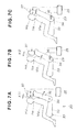
FIG. 7A, FIG. 7B and FIG. 7C are action views of a vehicle occupant protection apparatus according to the invention.
FIG. 7A shows an occupant Ma seated in the seat 30. The headrest 37 is normally positioned at its rearmost, as shown with broken lines.
Then, when it is predicted by impact predicting means 71, which will be explained with respect to FIG. 8A, that an impacting body is about to impact the vehicle from behind (impact prediction), in correspondence with a prediction signal from the impact predicting means 71 a control signal is issued from the headrest control unit 25 to the headrest actuating mechanism 26 (see FIG. 2). And the headrest actuating mechanism 26 advances the headrest 37 to the position shown with solid lines.
In this way, at the impact prediction stage, the gap X11 between the headrest 37 and the head Hd of the occupant Ma can be made small. As a result, the so-called behind-the-neck gap between the headrest 37 and the neck Ne of the occupant Ma can be forcibly made small in advance. Because the gap behind the neck Ne is made small immediately before the rear-end collision, even when the upper body of the occupant Ma falls rearward as a reaction to the rear-end collision, the load acting on the neck Ne of the occupant Ma can be lightened more certainly.
As a result of the upper body of the occupant Ma falling backward as a reaction to an impact from behind, an external force acts on the seat back 36 from the upper body. This external force causes the seat back 36 to fall backward, as shown in FIG. 7B. In correspondence with the size of the backward external force, the seat back 36 deforms. The amount of this deformation can be detected with the seat back deformation detector 23. The gap between the headrest 37 and the head Hd of the occupant Ma at this time is X12.
In correspondence with a detection signal from the seat back deformation detector 23, as shown in FIG. 7C a control signal is issued from the headrest control unit 25 to the headrest actuating mechanism 26 (see FIG. 2). And the headrest actuating mechanism 26 advances the headrest 37 further from the position shown with broken lines to the position shown with solid lines.
In this way, the gap between the headrest 37 and the head Hd of the occupant Ma can be made zero or nearly zero. As a result, the gap behind the neck Ne can be forcibly made small in advance. Because the gap behind the neck Ne is made small immediately after the impact from behind, even when the upper body of the occupant Ma falls rearward as a reaction to the impact, the load acting on the neck Ne of the occupant Ma can be lightened more certainly.
Next, control carried out by the headrest control unit 25 shown in FIG. 2 will be explained, on the basis of the flow chart shown in FIG. 8A through FIG. 8C and with reference to the maps shown in FIG. 9 through FIG. 11.
Step (hereinafter abbreviated to ST) 01: The inter-vehicle distance L1 is measured. As the first inter-vehicle distance L1, the actual present inter-vehicle distance is measured by the inter-vehicle distance detector 21 of FIG. 1.
ST02: A timer built in to the headrest control unit 25 shown in FIG. 2 is reset and then started.
ST03: It is determined whether or not the count time t1 of the timer has reached a preset extremely small fixed time t0. This is repeated until the count time t1 has reached the time t0, whereupon processing proceeds to ST04.
ST04: The next inter-vehicle distance L2 is measured. As the next inter-vehicle distance L2, the actual present inter-vehicle distance is measured, as in ST01.
In this way, by ST01 through ST04, the inter-vehicle distance is measured twice and the change between inter-vehicle distances L1 and L2 over a fixed time t0 is obtained.
ST05: It is determined whether or not the next inter-vehicle distance L2 is below a preset maximum proximity value L0, and on YES processing proceeds to ST06 and on NO processing returns to ST01. This “maximum proximity value L0” is a first reference value for determining whether or not there is a possibility of the vehicle behind impacting the own vehicle.
ST06: The vehicle speed V1 of the own vehicle is measured. As the vehicle speed V1, the actual present vehicle speed V1 is measured by the own vehicle speed detector 22 shown in FIG. 2.
ST07: The vehicle speed V2 of the vehicle behind is measured. The vehicle speed V2 is a value obtained by subtracting the next inter-vehicle distance L2 from the first inter-vehicle distance L1, dividing this difference by the count time t1, and adding this quotient to the vehicle speed V1. That is, the vehicle speed V2 is obtained by computing “V2=V1+(L1−L2)/t1”.
ST08: An estimated impact speed V3, i.e. a relative speed V3 of the vehicle behind with respect to the own vehicle speed V1, is calculated. The estimated impact speed V3 is the value obtained by subtracting the vehicle speed V1 of the own vehicle from the vehicle speed V2 of the vehicle behind. That is, the estimated impact speed V3 is obtained by computing “V3=V2−V1”.
ST09: An estimated impact time T1, i.e. an estimated time T1 to the vehicle behind impacting the own vehicle, is obtained by calculation. The estimated impact time T1 is a value obtained by dividing the next inter-vehicle distance L2 by the estimated impact speed V3. That is, the estimated impact time T1 is obtained by computing “T1=L2/V3”.
ST10: An impact time threshold value T0 is obtained from the own vehicle speed V1. Specifically, it is obtained on the basis of the map shown in FIG. 9.
FIG. 9 shows a map of impact time threshold values according to the invention. This map, with own vehicle speed V1 on the horizontal axis and impact time threshold value T0 on the vertical axis, is used to obtain an impact time threshold value T0 corresponding to the own vehicle speed V1.
From this map it can be seen that the impact time threshold value T0 maintains a high constant value when the vehicle speed V1 is close to 0, decreases in a rightwardly downward curve as the vehicle speed V1 increases, and substantially flattens out when the vehicle speed V1 increases further.
ST11: It is determined whether or not the estimated impact time T1 is below the impact time threshold value T0, and on YES processing proceeds to ST12 and on NO processing returns to ST01. Thus the “impact time threshold value T0” is a second reference value for determining whether or not there is a possibility of the vehicle behind impacting the own vehicle.
ST12: A required headrest advance X1 is obtained from the estimated impact speed V3. Specifically, it is obtained on the basis of the map shown in FIG. 12.
FIG. 12 is a map of required headrest advance according to the invention. This map, with estimated impact speed V3 on the horizontal axis and required headrest advance X1 on the vertical axis, is for obtaining a required headrest advance X1 corresponding to an estimated impact speed V3. In this map, the required headrest advance X1 is a value which is 0 when the estimated impact speed V3 is 0 and increases as the estimated impact speed V3 increases.
ST13: A flag F is set to 1.
Referring now to FIG. 8B, ST14: The actual headrest advance X2 is measured. The actual advance X2 is measured by the actual headrest advance detector 24 of FIG. 4.
ST15: A remaining headrest advance X3 is obtained. The remaining headrest advance X3 is obtained by subtracting the actual advance X2 from the required headrest advance X1. That is, the remaining headrest advance X3 is obtained by computing “X3=X1−X2”.
ST16: It is checked whether the remaining headrest advance X3 is greater than zero, i.e. whether there is some remaining headrest advance X3, and on YES processing proceeds to ST17 and on NO processing proceeds to ST19.
ST17: A headrest advance speed S is obtained from the remaining headrest advance X3. Specifically, it is obtained from the map shown in FIG. 11.
FIG. 11 is a map of headrest advance speed according to the invention. This map, with remaining headrest advance X3 on the horizontal axis and headrest advance speed S5 on the vertical axis, is used to obtain a headrest advance speed S1 corresponding to the remaining headrest advance X3. In the map, the headrest advance speed S5 is a value which is 0 when the remaining headrest advance X3 is 0 and increases as the remaining headrest advance X3 increases.
ST18: The speed of the motor of the headrest advancing part is determined so that the headrest advance speed becomes S1, the motor is driven at this speed, and processing returns to ST21.
ST19: The motor of the headrest advancing part is stopped.
ST20: It is checked whether or not the flag F is 1, and if YES then processing proceeds to ST21 in FIG. 8C and if NO then processing ends.
Thus in ST14 through ST18, the headrest is advanced by a required advance X1 corresponding to the estimated impact speed V3 (see FIG. 8A) by he motor. After that, in ST19 the motor is stopped. In ST20, when F=1, headrest advance control based on the estimated impact speed V3 is ended, and headrest advance control based on deformation of the seat back, shown in FIG. 8C, begins.
Referring now to FIG. 8C, ST21: A seat back deformation δ1 is measured. As the seat back deformation δ1, the actual present seat back deformation δ1 is measured by the seat back deformation detector 23 (see FIG. 3).
ST22: It is determined whether or not the seat back deformation δ1 is greater than a lower limit threshold value δ010), and on YES processing proceeds to ST23 and on NO processing returns to ST21. The “lower limit threshold value δ0” is a reference value for determining whether or not there has been an impact from behind. If δ10, it is determined that there has been an impact.
ST23: A required headrest advance X1 is obtained from the seat back deformation δ1. Specifically, it is obtained from the map shown in FIG. 12.
FIG. 12 is a map of required headrest advance according to the invention. This map, with seat back deformation δ1 on the horizontal axis and required headrest advance X1 on the vertical axis, is used to obtain a required headrest advance X1 corresponding to the seat back deformation δ1. In the map, the required headrest advance X1 is a value which is 0 when the deformation δ1 is 0 and increases as the deformation δ1 increases.
ST24: The actual advance X2 of the headrest is reset (X2=0).
ST25: The flag F is set to 0 and processing proceeds to ST14 of FIG. 8B.
Summarizing the foregoing explanation with reference to FIG. 1 through FIG. 3, a vehicle occupant protection apparatus 20 is made up of a headrest 37 mounted movably front/rearward to the top of a seat 30, a headrest actuating mechanism 26 for advancing the headrest 37, impact predicting means 71 (see FIG. 8A) for predicting an impact from behind, and a headrest control unit 25 for issuing a control signal to the headrest actuating mechanism 26 to advance the headrest 37 in correspondence with a prediction signal from the impact predicting means 71.
The headrest control unit 25 includes the impact predicting means 71 and relative speed detecting means 72 (see FIG. 8A) provided in the impact predicting means 71. That is, the steps ST04, ST05 and ST07 through ST11 constitute the impact predicting means 71. And the steps ST07 and ST08 constitute the relative speed detecting means 72.
Also, the headrest control unit 25 has means (steps ST12 through ST20) for issuing a control signal to the headrest actuating mechanism 26 to increase the advance of the headrest 37 in correspondence with a detection signal from the relative speed detecting means 72.
When the impact predicting means 71 predicts an impact, the required headrest advance X1 of the headrest 37 is made to change more suitably in correspondence with the relative speed V3 of the vehicle behind (impacting body) 12 with respect to the own vehicle 11.
When the own vehicle is impacted from behind, as a reaction to that the upper body of the occupant tends to fall backward. This amount of this falling backward is greater the greater is the relative speed V3. With respect to this, in this invention, the required headrest advance X1 of the headrest 37 is increased the greater is the relative speed V3, and the behind-the-neck gap can be made smaller immediately before an impact from behind. Therefore, even when as a reaction to suffering a rear-end collision the upper body of the occupant falls rearward, the load acting on the neck of the occupant can be lightened more rapidly and certainly.
Also, the headrest control unit 25 is constructed to issue a control signal to the headrest actuating mechanism 26 to increase the advance of the headrest 37 in correspondence with a detection signal from the seat back deformation detector 23 (see steps ST21 through ST25, ST14 through ST20 and the map of FIG. 12).
When the own vehicle is impacted from behind, as a reaction to that the upper body and the head of the occupant fall backward. Because the upper body is supported by the seat back 36, the amount by which it falls is relatively small. However, immediately before the impact the head is away from the headrest 37. Consequently, the amount by which the head falls is greater than the amount by which the upper body falls. This tendency is more marked the greater is the impact energy.
As a result of the upper body of the occupant falling rearward as a reaction to the impact from behind, an external force acts on the seat back 36 from the upper body. In correspondence with this external force the seat back 36 deforms. The greater is the impact energy the greater is the external force, and consequently the greater is the deformation 61 of the seat back 36. In this invention, the greater is the deformation δ1, the more the required headrest advance X1 of the headrest 37 is increased. Because of this, the behind-the-neck gap can be made smaller at the time of the impact. Consequently, when the upper body of the occupant falls rearward as a reaction to an impact, the load acting on the neck of the occupant can be lightened more rapidly and certainly.
And, the headrest control unit 25 is constructed to issue a control signal to the headrest actuating mechanism 26 to reduce the headrest advance speed S1 of the headrest 37 as the actual advance X2 detected by the actual headrest advance detector 24 increases (see steps ST15, ST17, ST18 and the map of FIG. 11).
As the headrest 37 advances, the behind-the-neck gap becomes smaller. With respect to this, the headrest 37 slows as it moves forward. And accordingly, even if the advancing headrest 37 hits the neck, the load which acts on the neck is extremely slight and essentially has no effect.
The vehicle occupant protection apparatus 20 of this invention can be applied whether the own vehicle 11 is stopped or moving.
Although in the preferred embodiment described above the rear impact predicting means 71 and the relative speed detecting means 72 were made functions of the headrest control unit 25, alternatively they may be provided separately from the control unit 25.
Also, the actual headrest advance detector 24 is not limited to the photoelectric rotary encoder made up of the pulse disc 61 and the sensor 62 shown in FIG. 4. For example, alternatively the motor 41 may be made a stepping motor incorporating a rotary encoder.
The present disclosure relates to the subject matter of Japanese Patent Application No. 2002-166083, filed Jun. 6, 2002, the disclosure of which is expressly incorporated herein by reference in its entirety.

Claims (3)

What is claimed is:
1. A vehicle occupant protection apparatus, comprising:
a headrest mounted movably front/rearward to the top of a seat of a vehicle;
a headrest actuating mechanism for advancing the headrest; and
a headrest control unit for drive-controlling the headrest actuating mechanism,
the headrest control unit including a means for predicting an impact from an impacting body into the vehicle from behind and a means for drive-controlling the headrest actuating mechanism provided by a prediction signal from the means for predicting an impact, and
wherein the headrest control unit responds to the prediction signal from the means for predicting an impact by controlling the headrest actuating mechanism before a rear-end impact occurs, such that the headrest advances forward by a first required amount determined by a first map defined by an estimated impact speed calculated from an inter-vehicle distance and the vehicle speed, said first required amount defining a gap between the headrest and head of the vehicle occupant, whereby when the rear-end impact occurs, the headrest advances by a second required amount determined by a second map defined by an amount of deformation of a seat back of the seat resulting from a backward falling of the vehicle occupant against the seat back as a reaction of the rear-end impact.
2. The protection apparatus according to claim 1, wherein the means for predicting an impact including a means for detecting the relative speed of the impacting body with respect to the vehicle, whereby the headrest control unit controls the headrest actuating mechanism to increase the advance of the headrest corresponding with an increase in relative speed of the impacting body.
3. The protection apparatus according to claim 1, wherein the headrest actuating mechanism including an actual headrest advance detector for detecting an actual headrest advance, whereby the headrest control unit controls the headrest actuating mechanism to reduce the speed of advance of the headrest when the actual advance detected by the actual headrest advance detector increases.
US10/439,042 2002-06-06 2003-05-14 Vehicle occupant protection apparatus Expired - Fee Related US6830278B2 (en)

Applications Claiming Priority (2)

Application Number Priority Date Filing Date Title
JP2002166083A JP4014938B2 (en) 2002-06-06 2002-06-06 Vehicle occupant protection device
JP2002-166083 2002-06-06

Publications (2)

Publication Number Publication Date
US20030227199A1 US20030227199A1 (en) 2003-12-11
US6830278B2 true US6830278B2 (en) 2004-12-14

Family

ID=29545828

Family Applications (1)

Application Number Title Priority Date Filing Date
US10/439,042 Expired - Fee Related US6830278B2 (en) 2002-06-06 2003-05-14 Vehicle occupant protection apparatus

Country Status (4)

Country Link
US (1) US6830278B2 (en)
EP (1) EP1369310B1 (en)
JP (1) JP4014938B2 (en)
DE (1) DE60301591T2 (en)

Cited By (10)

* Cited by examiner, † Cited by third party
Publication number Priority date Publication date Assignee Title
US6983989B1 (en) * 2004-09-24 2006-01-10 Lear Corporation Linear adjustable active head restraint
US20070145796A1 (en) * 2005-12-26 2007-06-28 Aisin Seiki Kabushiki Kaisha Headrest apparatus
US20070185635A1 (en) * 2003-05-15 2007-08-09 Bernhard Mattes Occupant-protection system for vehicles and method for activating an occupant-protection system for vehicles
US20080185894A1 (en) * 2006-10-05 2008-08-07 Lear Corporation Movable head restraint for improved vision
US20080290713A1 (en) * 2007-05-25 2008-11-27 Shigeo Oda Headrest device
US20090096468A1 (en) * 2005-11-17 2009-04-16 Aisin Seiki Kabushiki Kaisha Head rest device for vehicle
US20090243354A1 (en) * 2008-04-01 2009-10-01 Lear Corporation Active head restraint for a vehicle seat
US20100283306A1 (en) * 2009-05-06 2010-11-11 Lear Corporation Seat assembly and an adjustable head restraint assembly
US20110012400A1 (en) * 2007-08-29 2011-01-20 Mike Golin Vehicle seat with a stowable head restraint and an anti-whiplash system
US9174574B2 (en) 2011-10-19 2015-11-03 Magna Electronics Inc. Vehicle vision system for controlling a vehicle safety feature responsive to an imaging sensor having an exterior rearward field of view and before a collision occurs

Families Citing this family (41)

* Cited by examiner, † Cited by third party
Publication number Priority date Publication date Assignee Title
EP1284215A3 (en) * 2001-08-13 2006-01-18 Nissan Motor Co., Ltd. Headrest apparatus for vehicle
EP1712406B1 (en) 2004-01-30 2011-03-30 Toyota Boshoku Kabushiki Kaisha Head rest control device and active head rest
JP4492439B2 (en) 2004-06-16 2010-06-30 トヨタ紡織株式会社 Headrest
DE102004035454B4 (en) * 2004-07-22 2015-02-26 Robert Bosch Gmbh support element
DE102004042959A1 (en) * 2004-09-02 2006-03-09 Robert Bosch Gmbh Passenger protection device in a vehicle
KR101054759B1 (en) * 2004-09-30 2011-08-05 현대자동차주식회사 Active Headrest Device and its Control Method for Forecasting Back Collision
JP4810822B2 (en) * 2004-12-09 2011-11-09 トヨタ紡織株式会社 Headrest control device
JP4675621B2 (en) * 2004-12-28 2011-04-27 トヨタ紡織株式会社 Headrest control device
KR100865213B1 (en) 2004-12-09 2008-10-23 도요다 보쇼꾸 가부시키가이샤 Headrest control device
DE102005011244A1 (en) * 2005-03-11 2006-09-21 Robert Bosch Gmbh Method and device for estimating at least one feature
JP2007022450A (en) * 2005-07-20 2007-02-01 Aisin Seiki Co Ltd Seat device for vehicle
WO2006126450A1 (en) * 2005-05-25 2006-11-30 Aisin Seiki Kabushiki Kaisha Seat device for vehicle
JP2006327373A (en) * 2005-05-25 2006-12-07 Aisin Seiki Co Ltd Vehicular seat device
JP4654815B2 (en) * 2005-07-26 2011-03-23 アイシン精機株式会社 Vehicle headrest device
JP4770314B2 (en) * 2005-07-27 2011-09-14 アイシン精機株式会社 Vehicle seat device
JP4306673B2 (en) 2005-11-08 2009-08-05 トヨタ自動車株式会社 Crew protection device
JP4018713B2 (en) 2005-11-17 2007-12-05 アイシン精機株式会社 Headrest device
JP4342521B2 (en) 2006-01-30 2009-10-14 アイシン精機株式会社 Headrest device
US7232187B1 (en) * 2006-03-30 2007-06-19 Ford Global Technologies, Llc Head restraint for automotive vehicle
JP4199788B2 (en) * 2006-08-23 2008-12-17 トヨタ自動車株式会社 Headrest control device and control method
JP2008081088A (en) * 2006-09-29 2008-04-10 Aisin Seiki Co Ltd Headrest adjusting device and head rest adjusting method
JP4735516B2 (en) * 2006-11-10 2011-07-27 トヨタ自動車株式会社 Rear collision prediction device
JP4306751B2 (en) 2007-03-15 2009-08-05 トヨタ自動車株式会社 Headrest control device and active headrest
JP4404915B2 (en) 2007-04-19 2010-01-27 三菱電機株式会社 Vehicle occupant protection device
DE102007041995A1 (en) * 2007-09-04 2009-03-05 Volkswagen Ag Headrest for vehicle seat, comprises base support element and impact element, where headrest comfort position is changed with pre-determined acceleration by movement of impact element opposite to base support element
US8205941B2 (en) 2008-07-30 2012-06-26 Trw Vehicle Safety Systems Inc. Active head restraint for a vehicle seat
DE102008052953A1 (en) * 2008-10-23 2010-04-29 Volkswagen Ag Crash-active headrest positioning method for seat of motor vehicle, involves moving headrest to stand-by position that is temporally upstream of crash position, between comfort position and crash position
DE102008057792B4 (en) * 2008-11-17 2013-08-14 Johnson Controls Gmbh Crash-active headrest with a locking push button
DE102009055956B4 (en) 2009-11-27 2012-05-31 Fachhochschule Kaiserslautern Method and device for avoiding or reducing the risk of injury to the vehicle occupants in a rear-end collision
JP5455596B2 (en) * 2009-12-14 2014-03-26 Udトラックス株式会社 Collision damage reduction device
DE102010044339B4 (en) * 2010-09-03 2015-10-01 Johnson Controls Gmbh Horizontally adjustable headrest
US20130158809A1 (en) * 2011-12-15 2013-06-20 Ford Global Technologies, Llc Method and system for estimating real-time vehicle crash parameters
KR101389067B1 (en) * 2012-05-02 2014-04-23 경북대학교 산학협력단 safety belt system for vehicle
JP6442192B2 (en) * 2014-08-26 2018-12-19 株式会社Subaru Crew protection device
CN104859573A (en) * 2015-05-20 2015-08-26 浙江吉利汽车研究院有限公司 Protection method and device for rear-end collision
CN104842836B (en) * 2015-06-01 2018-07-17 延锋安道拓座椅有限公司 A kind of induction head support structure for chair
DE102016110496A1 (en) * 2016-06-07 2017-12-07 Dr. Ing. H.C. F. Porsche Aktiengesellschaft Headrest for a motor vehicle seat
US11618380B2 (en) * 2017-06-12 2023-04-04 Continental Automotive Gmbh Rear pre-crash safety system
US10384566B2 (en) * 2017-08-25 2019-08-20 Ford Global Technologies, Llc Vehicle seat assembly
DE102018109419A1 (en) * 2018-04-19 2019-10-24 Faurecia Autositze Gmbh Adjustable headrest for a motor vehicle seat
US10926684B2 (en) * 2018-08-20 2021-02-23 Windsor Machine and Stamping (2009) Ltd. Four-way electric power actuation head restraint with automated deployment

Citations (20)

* Cited by examiner, † Cited by third party
Publication number Priority date Publication date Assignee Title
US3592508A (en) * 1970-01-14 1971-07-13 Gen Motors Corp Power actuated headrest assembly
US4586848A (en) * 1984-11-27 1986-05-06 British Columbia Research Council Method of storing logs
US5288129A (en) * 1992-04-21 1994-02-22 Tachi-S Co., Ltd. Structure of a vertically movable powered headrest
US5378043A (en) * 1993-06-01 1995-01-03 General Motors Corporation Vehicle pivotal headrest
US5684701A (en) 1995-06-07 1997-11-04 Automotive Technologies International, Inc. Method and apparatus for sensing a vehicle crash
US5694320A (en) * 1995-06-07 1997-12-02 Automotive Technologies Intl, Inc. Rear impact occupant protection apparatus
US5882071A (en) * 1996-08-28 1999-03-16 Trw Occupant Restraint Systems Gmbh Vehicle seat with headrest adjustable on the backrest
US5934750A (en) * 1996-02-26 1999-08-10 Trw Occupant Restraint Systems Gmbh Vehicle seat
JP2000006751A (en) 1998-06-26 2000-01-11 Mazda Motor Corp Occupant protection device for vehicle
US6019424A (en) * 1997-12-03 2000-02-01 Ewald Witte Gmbh & Co. Kg Headrest, in particular in motor vehicles
US6024406A (en) * 1997-07-03 2000-02-15 Bertrand Faure Equipements S.A. Vehicle seat provided with a device for protecting the neck in the event of impact from behind
US6088640A (en) * 1997-12-17 2000-07-11 Automotive Technologies International, Inc. Apparatus for determining the location of a head of an occupant in the presence of objects that obscure the head
US6196580B1 (en) 1998-11-11 2001-03-06 Daimlerchrysler Ag Method of controlling an active occupant-head protection system in a vehicle
US6331014B1 (en) * 2000-07-11 2001-12-18 Automotive Technologies International Inc. Vehicular seats including occupant protection apparatus
US20030015898A1 (en) * 1997-12-17 2003-01-23 Breed David S. System and method for moving a headrest based on anticipatory sensing
US6520577B2 (en) * 2000-06-21 2003-02-18 Nissan Motor Co., Ltd. Vehicle seat
US6609053B1 (en) * 1995-06-07 2003-08-19 Automotive Technologies International, Inc. Method and apparatus for sensing a vehicle crash
US6607242B2 (en) * 2000-12-13 2003-08-19 Lear Corporation Head restraint assembly
US20040000807A1 (en) * 2002-06-26 2004-01-01 Nissan Motor Co., Ltd. Vehicle headrest apparatus
US20040012234A1 (en) * 2002-07-18 2004-01-22 Nhk Spring Co., Ltd. Vehicular seat including forward movable headrest

Family Cites Families (1)

* Cited by examiner, † Cited by third party
Publication number Priority date Publication date Assignee Title
JP3496556B2 (en) * 1999-02-16 2004-02-16 マツダ株式会社 Vehicle occupant protection system

Patent Citations (20)

* Cited by examiner, † Cited by third party
Publication number Priority date Publication date Assignee Title
US3592508A (en) * 1970-01-14 1971-07-13 Gen Motors Corp Power actuated headrest assembly
US4586848A (en) * 1984-11-27 1986-05-06 British Columbia Research Council Method of storing logs
US5288129A (en) * 1992-04-21 1994-02-22 Tachi-S Co., Ltd. Structure of a vertically movable powered headrest
US5378043A (en) * 1993-06-01 1995-01-03 General Motors Corporation Vehicle pivotal headrest
US5684701A (en) 1995-06-07 1997-11-04 Automotive Technologies International, Inc. Method and apparatus for sensing a vehicle crash
US5694320A (en) * 1995-06-07 1997-12-02 Automotive Technologies Intl, Inc. Rear impact occupant protection apparatus
US6609053B1 (en) * 1995-06-07 2003-08-19 Automotive Technologies International, Inc. Method and apparatus for sensing a vehicle crash
US5934750A (en) * 1996-02-26 1999-08-10 Trw Occupant Restraint Systems Gmbh Vehicle seat
US5882071A (en) * 1996-08-28 1999-03-16 Trw Occupant Restraint Systems Gmbh Vehicle seat with headrest adjustable on the backrest
US6024406A (en) * 1997-07-03 2000-02-15 Bertrand Faure Equipements S.A. Vehicle seat provided with a device for protecting the neck in the event of impact from behind
US6019424A (en) * 1997-12-03 2000-02-01 Ewald Witte Gmbh & Co. Kg Headrest, in particular in motor vehicles
US6088640A (en) * 1997-12-17 2000-07-11 Automotive Technologies International, Inc. Apparatus for determining the location of a head of an occupant in the presence of objects that obscure the head
US20030015898A1 (en) * 1997-12-17 2003-01-23 Breed David S. System and method for moving a headrest based on anticipatory sensing
JP2000006751A (en) 1998-06-26 2000-01-11 Mazda Motor Corp Occupant protection device for vehicle
US6196580B1 (en) 1998-11-11 2001-03-06 Daimlerchrysler Ag Method of controlling an active occupant-head protection system in a vehicle
US6520577B2 (en) * 2000-06-21 2003-02-18 Nissan Motor Co., Ltd. Vehicle seat
US6331014B1 (en) * 2000-07-11 2001-12-18 Automotive Technologies International Inc. Vehicular seats including occupant protection apparatus
US6607242B2 (en) * 2000-12-13 2003-08-19 Lear Corporation Head restraint assembly
US20040000807A1 (en) * 2002-06-26 2004-01-01 Nissan Motor Co., Ltd. Vehicle headrest apparatus
US20040012234A1 (en) * 2002-07-18 2004-01-22 Nhk Spring Co., Ltd. Vehicular seat including forward movable headrest

Cited By (21)

* Cited by examiner, † Cited by third party
Publication number Priority date Publication date Assignee Title
US20070185635A1 (en) * 2003-05-15 2007-08-09 Bernhard Mattes Occupant-protection system for vehicles and method for activating an occupant-protection system for vehicles
US6983989B1 (en) * 2004-09-24 2006-01-10 Lear Corporation Linear adjustable active head restraint
US20090096468A1 (en) * 2005-11-17 2009-04-16 Aisin Seiki Kabushiki Kaisha Head rest device for vehicle
US7986151B2 (en) 2005-11-17 2011-07-26 Aisin Seiki Kabushiki Kaisha Head rest device for vehicle
US20070145796A1 (en) * 2005-12-26 2007-06-28 Aisin Seiki Kabushiki Kaisha Headrest apparatus
US7350860B2 (en) 2005-12-26 2008-04-01 Aisin Seiki Kabushiki Kaisha Headrest apparatus
US20080185894A1 (en) * 2006-10-05 2008-08-07 Lear Corporation Movable head restraint for improved vision
US20080290713A1 (en) * 2007-05-25 2008-11-27 Shigeo Oda Headrest device
US7648200B2 (en) * 2007-05-25 2010-01-19 Toyoshi Fukuda Headrest device
US20110012400A1 (en) * 2007-08-29 2011-01-20 Mike Golin Vehicle seat with a stowable head restraint and an anti-whiplash system
US7894960B2 (en) 2008-04-01 2011-02-22 Lear Corporation Active head restraint for a vehicle seat
US20090243354A1 (en) * 2008-04-01 2009-10-01 Lear Corporation Active head restraint for a vehicle seat
US20100283306A1 (en) * 2009-05-06 2010-11-11 Lear Corporation Seat assembly and an adjustable head restraint assembly
US8939512B2 (en) * 2009-05-06 2015-01-27 Lear Corporation Seat assembly and an adjustable head restraint assembly
US9174574B2 (en) 2011-10-19 2015-11-03 Magna Electronics Inc. Vehicle vision system for controlling a vehicle safety feature responsive to an imaging sensor having an exterior rearward field of view and before a collision occurs
US9908495B2 (en) 2011-10-19 2018-03-06 Magna Electronics Inc. Vehicle safety system for controlling a safety feature
US10239479B2 (en) 2011-10-19 2019-03-26 Magna Electronics Inc. Vehicle safety system for controlling a safety feature
US10632950B2 (en) 2011-10-19 2020-04-28 Magna Electronics Inc. Vehicular safety system for controlling a safety feature
US10974674B2 (en) 2011-10-19 2021-04-13 Magna Electronics Inc. Vehicular safety system for controlling a safety feature
US11548461B2 (en) 2011-10-19 2023-01-10 Magna Electronics Inc. Vehicular safety system for controlling a safety feature
US11738705B2 (en) 2011-10-19 2023-08-29 Magna Electronics Inc. Vehicular safety system for controlling a safety feature

Also Published As

Publication number Publication date
JP4014938B2 (en) 2007-11-28
EP1369310B1 (en) 2005-09-14
EP1369310A1 (en) 2003-12-10
JP2004009891A (en) 2004-01-15
DE60301591T2 (en) 2006-06-14
US20030227199A1 (en) 2003-12-11
DE60301591D1 (en) 2005-10-20

Similar Documents

Publication Publication Date Title
US6830278B2 (en) Vehicle occupant protection apparatus
US7138938B1 (en) System and method for preemptively sensing an object and selectively operating both a collision countermeasure system and a parking assistance system aboard an automotive vehicle
US6296306B1 (en) Vehicle seat
EP1681213B1 (en) Collision behavior control apparatus
US6478373B1 (en) Automotive seat—seat back with integrated protective device and process to prevent injuries caused by accident
US5646613A (en) System for minimizing automobile collision damage
US7640090B2 (en) Active headrest of a vehicle that rotates horizontally and moves laterally based on angle and direction of inertia force caused by rear-impact
US20060262432A1 (en) Review correcting/controlling system for vehicle
EP1029736B1 (en) A passenger protecting apparatus for use in a vehicle
EP1749687A1 (en) Automatic collision management system
US11897405B2 (en) Collision prediction determination device and vulnerable road user protection system
US6477466B1 (en) Device for adjusting the height positioning of the body of a vehicle
WO2008041494A1 (en) Head rest adjusting device and method
MXPA01011776A (en) Front hood assembly.
CN101549660A (en) Active head restraint system for a vehicle seat
CN101264738A (en) Automobile seat with dodging function and correlated control system thereof
CN114043908B (en) Protection system and protection method for dealing with automobile rear-end collision
JP2003260994A (en) Front bumper device for vehicle
CN113500982A (en) Active brake pedal control system and method
JP2009078639A (en) Occupant crash protection device
WO2023231372A1 (en) Safety device control method and device
CN210488312U (en) Outdoor robot
JP4356878B2 (en) Vehicle occupant protection device
CA1299987C (en) Vehicle safety device
KR20220134240A (en) Active Pre Safety Seat System of Vehicle and Method for Improving Control Speed of Pre Safety Seat Thereof

Legal Events

Date Code Title Description
AS Assignment

Owner name: HONDA GIKEN KOGYO KABUSHIKI KAISHA, JAPAN

Free format text: ASSIGNMENT OF ASSIGNORS INTEREST;ASSIGNORS:YOSHIZAWA, RYOZO;NAKANISHI, ISAMU;REEL/FRAME:014087/0795

Effective date: 20030501

FEPP Fee payment procedure

Free format text: PAYOR NUMBER ASSIGNED (ORIGINAL EVENT CODE: ASPN); ENTITY STATUS OF PATENT OWNER: LARGE ENTITY

FPAY Fee payment

Year of fee payment: 4

FPAY Fee payment

Year of fee payment: 8

REMI Maintenance fee reminder mailed
LAPS Lapse for failure to pay maintenance fees
STCH Information on status: patent discontinuation

Free format text: PATENT EXPIRED DUE TO NONPAYMENT OF MAINTENANCE FEES UNDER 37 CFR 1.362

FP Lapsed due to failure to pay maintenance fee

Effective date: 20161214