US683025A - Mowing-machine. - Google Patents
Mowing-machine. Download PDFInfo
- Publication number
- US683025A US683025A US3078000A US1900030780A US683025A US 683025 A US683025 A US 683025A US 3078000 A US3078000 A US 3078000A US 1900030780 A US1900030780 A US 1900030780A US 683025 A US683025 A US 683025A
- Authority
- US
- United States
- Prior art keywords
- arm
- rod
- sleeve
- shaft
- shoe
- Prior art date
- Legal status (The legal status is an assumption and is not a legal conclusion. Google has not performed a legal analysis and makes no representation as to the accuracy of the status listed.)
- Expired - Lifetime
Links
Images

Classifications
-
- A—HUMAN NECESSITIES
- A01—AGRICULTURE; FORESTRY; ANIMAL HUSBANDRY; HUNTING; TRAPPING; FISHING
- A01D—HARVESTING; MOWING
- A01D34/00—Mowers; Mowing apparatus of harvesters
- A01D34/01—Mowers; Mowing apparatus of harvesters characterised by features relating to the type of cutting apparatus
- A01D34/02—Mowers; Mowing apparatus of harvesters characterised by features relating to the type of cutting apparatus having reciprocating cutters
- A01D34/28—Adjusting devices for the cutter-bar
- A01D34/283—Adjustment of the cutter bar in a vertical plane, i.e. to adjust the angle between the cutter bar and the soil
Definitions
- W ihyzssz s Tm nonms warms to. PN01Q-LXTHO.. wuumorou. n. c.
- My invention relates to an improvement in mowing-machines; and it consists in the pecu'liar construction and combination of devices hereinafter fully set forth,- and pointed out in the claims.
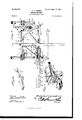
- Figure l is a perspective view of a mowing-machine embodying my improvements.
- Fig. 2 is a detail perspective view of the pitman which operates the sickle-bar.
- Fig. 3 is a top plan view, partly in section, of my improved mowingmachine.
- Fig. 4 is a detail perspective view of the sickle-bar.
- Fig. 5 is a detail perspective view of the shoe and its connections.
- the frame 1 of my improved mowing-machine comprises the axle-sheath 2, forwardextending arm 3 on the left-hand side of the frame, and the bracket-arm 4.
- the tongue 5 is secured on the axle-sheath 2 and to the bracket arm 4.
- the axle shaft 6 has its bearing in the axle-sheath 2, and on the ends of the axle-shaft are the traction-wheels 7, which are loose thereon and are connected to the axle-shaft by pawl-and-ratchet mechanisms 8, of the usual construction, by means of which power is communicated to the axleshaft through .
- the traction-wheels and the latter are adapted to rotate independently of each other to permit the machine to be turned.
- a cam-wheel 9 is secured on the axle-shaft and is loose thereon, and said camwheel is provided on its periphery with a waved cam 10.
- a clutch 11 is splined on the axle-shaft and adapted to engage the camwheel to lock the latter to the axle-shaft. Said clutch is engaged by a spring-pressed operating-rod 12.
- the said rod which is supported in guiding-ears 13 on the rear side of the frame, is connected to a foot clutch-lever 14 by a rod 15.
- the said clutch-lever has its bearings in ears 16 on the rear side of the frame 1 and is adjacent to the foot of the spring-bar 17, which supports the seat 18.
- a rock-shaft 19 is disposed longitudinally in a bearing 20,
- the said arm has its free end formed into a spindle 27, on which is pivoted a sleeve 28.
- the said sleeve is formed at its outer end with a transversely-disposed bearing 29, and on the rear side of the said sleeve is formed a depending arm 30.
- the shoe 31, to which is attached the finger-bar 32, is provided on its upper side with ears 33, which bear against the front and rear sides of the hearing 29 and are pivotally connected thereto by a hinge-shaft 34 in said bearing.
- the said shoe has on its inner side near its rear end an upwardly-extending arm 35.
- a rod 36 has its outer end pivotally connected to the upper end of the arm 35, as at 37, and the inner end of the said rod bears under the tongue and is guided in an eye or other suitable guide 38.
- a rock-shaft 39 is disposed longitudinally and has its bearings 40 41, respectively, on the tongue and on the rear side of frame 1.
- Said rockeshaft has an arm 42 at its front end, which is connected to the rod 36 by a link-rod 43, and at the rear end of the said rock-shaft is a lever 44.
- Atilting lever 45 is fulcrumed on a bearing 46 on the front side of the axle-sheath and is provided with a spring-pressed locking-dog 47, which by engagement with a sector 48 secures the tilting lever at any desired adjustment.
- a brace-rod 50 is pivotally attached at its rear end to an car 51, which depends from the lower side of the axlesheath, and the front end of the said bracerod is connected to the spindle 27.
- the sicklebar 52 has its head 53 provided on its upper side with a stud 54, which terminates in a ball 55.
- the pitman has one end bifurcated, as at 57, and a socket 58 formed therein to receive the ball 55.
- the outer end of the said pitman is connected to the lower end of the arm 24, which is rocked by shaft 19.
- the operation of my invention is as follows:
- the cam-wheel 9 communicates rocking motion to the shaft 20 through the arm 21, head 22, and antifriction-rollers 23, and reciprocating motion is communicated to the sicklebar through the rock-arm 24, which is actuated by the shaft 20 and the pitman 56.
- the clutch 11 and lever 14.- the cutting mechanism may be thrown into and out of gear.
- the lever 44 By operating the lever 44 the outer end of the arm 26 may be raised and lowered to raise and lower the cutting mechanism, and by means of the tilting lever and its connections hereinbefore described the sleeve 28 may be turned on the spindle 27, so as to tilt or incline the cutting mechanism which is car ried by the shoe to any angle required.
- I claim- 1 The combination, in a mowing-machine, of a frame, a transversely-disposed arm having one end pivoted thereto, a brace-rod pivotally connected to said frame and to said arm, a sleeve adapted to turn on said arm, means to turn said sleeve on said arm, and secure the same at any required adjustment, a shoe pivotally attached to said sleeve, the pivotal axis of said shoe being at right angles to that of said sleeve, whereby said shoe may be turned on said arm by turning said sleeve to raise or lower the front end of said shoe, the latter having an upwardly-projecting arm, an endwise-movable rod, connected to said arm and disposed parallel with said transversely-disposed pivoted arm, means to support and guide said rod, and a lever and means connecting the same to said rod, substantially as described.
Landscapes
- Life Sciences & Earth Sciences (AREA)
- Environmental Sciences (AREA)
- Harvester Elements (AREA)
Description
No. 683,025. Patented Sept. 24, 1am.
E. P. DURAND.
IIIOWING MACHINE.
(Application filed Sept. 22, 1900.)
2 Sheets-Sheet I.
(No Model.)
m i: i y/m w\ Q Patented'Sapt. 24, I901. E. P. DURAND.
MOWING MACHINE:
(Application filed Sept. 22, 1900.
2 spam-sheer. 2.
(No Model.)
W ihyzssz s Tm: nonms warms to. PN01Q-LXTHO.. wuumorou. n. c.
UNITED STATES PATENT oFFm-E.
. EMILE PAUL DURAND, OF SHERMAN, ILLINOIS.
MOWlNG-MACHINE.
SPECIFICATION forming part of Letters Patent-No. 683,025, dated September 24, 1901.
Application filed S'ep'teinber 22,1900. Serial No. 30,780. (No model.)
To all whom it may concern:
Be it known that I, EMILELPAUL DURAND, a citizen of the United States, residing at Sherman, in the county of Sangamon and State of Illinois, have invented a newand useful Mowing-Machine, of which the following is a specification.
My invention relates to an improvement in mowing-machines; and it consists in the pecu'liar construction and combination of devices hereinafter fully set forth,- and pointed out in the claims. I
In the accompanying drawings, Figure l is a perspective view of a mowing-machine embodying my improvements. Fig. 2 is a detail perspective view of the pitman which operates the sickle-bar. Fig. 3 is a top plan view, partly in section, of my improved mowingmachine. Fig. 4 is a detail perspective view of the sickle-bar. Fig. 5 is a detail perspective view of the shoe and its connections.
The frame 1 of my improved mowing-machine comprises the axle-sheath 2, forwardextending arm 3 on the left-hand side of the frame, and the bracket-arm 4. The tongue 5 is secured on the axle-sheath 2 and to the bracket arm 4. The axle shaft 6 has its bearing in the axle-sheath 2, and on the ends of the axle-shaft are the traction-wheels 7, which are loose thereon and are connected to the axle-shaft by pawl-and-ratchet mechanisms 8, of the usual construction, by means of which power is communicated to the axleshaft through .the traction-wheels and the latter are adapted to rotate independently of each other to permit the machine to be turned. A cam-wheel 9 is secured on the axle-shaft and is loose thereon, and said camwheel is provided on its periphery with a waved cam 10. A clutch 11 is splined on the axle-shaft and adapted to engage the camwheel to lock the latter to the axle-shaft. Said clutch is engaged by a spring-pressed operating-rod 12. The said rod, which is supported in guiding-ears 13 on the rear side of the frame, is connected to a foot clutch-lever 14 by a rod 15. The said clutch-lever has its bearings in ears 16 on the rear side of the frame 1 and is adjacent to the foot of the spring-bar 17, which supports the seat 18. A rock-shaft 19 is disposed longitudinally in a bearing 20,
formed in the front end of the arm 3. To the rear end of the said rock-shaft is secured an arm 21, on which is pivoted a head 22, the said head carrying a pair of antifriction-rollers 23, which engage opposite sides of the waved-cam flange 10. To the front end of the rock-shaft 19 is secured a downward-extending rock-arm 24. The front end of the arm 3 is provided with a spindle 25. On the spindle 25 is pivoted one end of an arm 26. The said arm has its free end formed into a spindle 27, on which is pivoted a sleeve 28.- The said sleeve is formed at its outer end with a transversely-disposed bearing 29, and on the rear side of the said sleeve is formed a depending arm 30. The shoe 31, to which is attached the finger-bar 32, is provided on its upper side with ears 33, which bear against the front and rear sides of the hearing 29 and are pivotally connected thereto by a hinge-shaft 34 in said bearing.- The said shoe has on its inner side near its rear end an upwardly-extending arm 35. A rod 36 has its outer end pivotally connected to the upper end of the arm 35, as at 37, and the inner end of the said rod bears under the tongue and is guided in an eye or other suitable guide 38. A rock-shaft 39 is disposed longitudinally and has its bearings 40 41, respectively, on the tongue and on the rear side of frame 1. Said rockeshaft has an arm 42 at its front end, which is connected to the rod 36 by a link-rod 43, and at the rear end of the said rock-shaft is a lever 44. Atilting lever 45 is fulcrumed on a bearing 46 on the front side of the axle-sheath and is provided with a spring-pressed locking-dog 47, which by engagement with a sector 48 secures the tilting lever at any desired adjustment. To the lower end of the tilting lever is connected the rear end of a rod 49, the front end of the said rod being connected to the lower end of the arm 30 of sleeve 28. A brace-rod 50 is pivotally attached at its rear end to an car 51, which depends from the lower side of the axlesheath, and the front end of the said bracerod is connected to the spindle 27. The sicklebar 52 has its head 53 provided on its upper side with a stud 54, which terminates in a ball 55. The pitman has one end bifurcated, as at 57, and a socket 58 formed therein to receive the ball 55. The outer end of the said pitman is connected to the lower end of the arm 24, which is rocked by shaft 19.
The operation of my invention is as follows: The cam-wheel 9 communicates rocking motion to the shaft 20 through the arm 21, head 22, and antifriction-rollers 23, and reciprocating motion is communicated to the sicklebar through the rock-arm 24, which is actuated by the shaft 20 and the pitman 56. By means of the clutch 11 and lever 14.- the cutting mechanism may be thrown into and out of gear. By operating the lever 44 the outer end of the arm 26 may be raised and lowered to raise and lower the cutting mechanism, and by means of the tilting lever and its connections hereinbefore described the sleeve 28 may be turned on the spindle 27, so as to tilt or incline the cutting mechanism which is car ried by the shoe to any angle required.
Having thus described my invention, I claim- 1. The combination, in a mowing-machine, of a frame, a transversely-disposed arm having one end pivoted thereto, a brace-rod pivotally connected to said frame and to said arm, a sleeve adapted to turn on said arm, means to turn said sleeve on said arm, and secure the same at any required adjustment, a shoe pivotally attached to said sleeve, the pivotal axis of said shoe being at right angles to that of said sleeve, whereby said shoe may be turned on said arm by turning said sleeve to raise or lower the front end of said shoe, the latter having an upwardly-projecting arm, an endwise-movable rod, connected to said arm and disposed parallel with said transversely-disposed pivoted arm, means to support and guide said rod, and a lever and means connecting the same to said rod, substantially as described.
2. The combination in a mowing-machine, of a frame, a transversely-disposed arm having one end pivoted thereto, a brace-rod pivotally connected to said frame and to said arm, a sleeve adapted to turn on said arm, means to turn said sleeve on said arm and secure the same at any required adjustment, a shoe pivotally attached to said sleeve, the pivotal-axis of said shoe being at right angles to that of said sleeve, whereby said shoe may be turned on said arm by turning said sleeve, to raise or lower the front end of said shoe, a finger-bar having one end rigidly attached to and carried by said shoe, the latter also having an upwardly-projecting arm, an endwise-movable rod, connected to said arm and disposed parallel with said transverselydisposed pivoted arm, means to support and guide said rod, a lever and means connecting the same to said rod, a cutter-bar on said finger-bar, a pitman, a flexible connection between the same and said cutter-bar, and means to reciprocate said pitman, substantially as described.
In testimony that I claim the foregoing as my own I have hereto affixed my signature in the presence of two witnesses.
EMILE PAUL DURAND.
Witnesses:
J. H. CORBLEY, W. F. WOLF.
Priority Applications (1)
| Application Number | Priority Date | Filing Date | Title |
|---|---|---|---|
| US3078000A US683025A (en) | 1900-09-22 | 1900-09-22 | Mowing-machine. |
Applications Claiming Priority (1)
| Application Number | Priority Date | Filing Date | Title |
|---|---|---|---|
| US3078000A US683025A (en) | 1900-09-22 | 1900-09-22 | Mowing-machine. |
Publications (1)
| Publication Number | Publication Date |
|---|---|
| US683025A true US683025A (en) | 1901-09-24 |
Family
ID=2751568
Family Applications (1)
| Application Number | Title | Priority Date | Filing Date |
|---|---|---|---|
| US3078000A Expired - Lifetime US683025A (en) | 1900-09-22 | 1900-09-22 | Mowing-machine. |
Country Status (1)
| Country | Link |
|---|---|
| US (1) | US683025A (en) |
-
1900
- 1900-09-22 US US3078000A patent/US683025A/en not_active Expired - Lifetime
Similar Documents
| Publication | Publication Date | Title |
|---|---|---|
| US123631A (en) | Improvement in harvesters | |
| US645395A (en) | Mowing-machine. | |
| US233426A (en) | Mowing-machine | |
| USRE1964E (en) | Improvement in harvesters | |
| US128456A (en) | Improvement in cutting apparatus for harvesters | |
| US329709A (en) | Mowing-machine | |
| US89509A (en) | Improvement in harvesters | |
| US175511A (en) | Improvement in mowing-machines | |
| US253477A (en) | Eeaper and mower | |
| USRE2639E (en) | Improvement in mowing-machines | |
| US576914A (en) | Mowing-machine | |
| US604353A (en) | Mowing-machine | |
| US87488A (en) | Improvement in harvesters | |
| US1264079A (en) | Mower. | |
| US141597A (en) | Joseph h | |
| US747384A (en) | Mowing-machine. | |
| US97126A (en) | William h | |
| US28283A (en) | Improvement in mowing and reaping machines | |
| US456782A (en) | Mower | |
| US135394A (en) | Improvement in harvesters | |
| US197921A (en) | Improvement in mowing-machines | |
| US771516A (en) | Mowing-machine. | |
| US414063A (en) | Mowing-machine | |
| US455482A (en) | Mowing-machine | |
| US95372A (en) | Improvement in harvesters |