US6829065B1 - Glass supporting device of scanner - Google Patents
Glass supporting device of scanner Download PDFInfo
- Publication number
- US6829065B1 US6829065B1 US09/667,584 US66758400A US6829065B1 US 6829065 B1 US6829065 B1 US 6829065B1 US 66758400 A US66758400 A US 66758400A US 6829065 B1 US6829065 B1 US 6829065B1
- Authority
- US
- United States
- Prior art keywords
- end portion
- glass sheet
- scanner
- supporting device
- upper cover
- Prior art date
- Legal status (The legal status is an assumption and is not a legal conclusion. Google has not performed a legal analysis and makes no representation as to the accuracy of the status listed.)
- Expired - Fee Related, expires
Links
Images


Classifications
-
- H—ELECTRICITY
- H04—ELECTRIC COMMUNICATION TECHNIQUE
- H04N—PICTORIAL COMMUNICATION, e.g. TELEVISION
- H04N1/00—Scanning, transmission or reproduction of documents or the like, e.g. facsimile transmission; Details thereof
- H04N1/04—Scanning arrangements, i.e. arrangements for the displacement of active reading or reproducing elements relative to the original or reproducing medium, or vice versa
- H04N1/10—Scanning arrangements, i.e. arrangements for the displacement of active reading or reproducing elements relative to the original or reproducing medium, or vice versa using flat picture-bearing surfaces
- H04N1/1061—Details relating to flat picture-bearing surfaces, e.g. transparent platen
- H04N1/1065—Support or mounting of the flat picture-bearing surface
-
- H—ELECTRICITY
- H04—ELECTRIC COMMUNICATION TECHNIQUE
- H04N—PICTORIAL COMMUNICATION, e.g. TELEVISION
- H04N1/00—Scanning, transmission or reproduction of documents or the like, e.g. facsimile transmission; Details thereof
- H04N1/04—Scanning arrangements, i.e. arrangements for the displacement of active reading or reproducing elements relative to the original or reproducing medium, or vice versa
- H04N1/10—Scanning arrangements, i.e. arrangements for the displacement of active reading or reproducing elements relative to the original or reproducing medium, or vice versa using flat picture-bearing surfaces
- H04N1/1013—Scanning arrangements, i.e. arrangements for the displacement of active reading or reproducing elements relative to the original or reproducing medium, or vice versa using flat picture-bearing surfaces with sub-scanning by translatory movement of at least a part of the main-scanning components
Definitions
- the present invention relates to a glass supporting device of a scanner, and especially to a glass supporting device used in a platform scanner, wherein a track is formed for replacing the prior art double face tape or a modifying sheet. Therefore, the glass sheet can be easily assembled and detached and thus the assembling work can be performed quickly and the cost for detaching parts are low.
- scanners are widely used in graphing or text processing.
- the primary function of a scanner is to scan a document or a picture as a form readable by a computer. For example, several photographs can be scanned through a scanner into image files for being read by a computer. Then, these image files are inserted into a word document to be as a report with image and text.
- the current scanner can be divided as a platform scanner and a portable scanner. Furthermore, in some products, different types of scanners are integrated.
- the assembly structure includes an upper cover, a lower cover (not shown), a glass sheet 2 a , a double face tape 2 a and a modifying sheet 4 a .
- the upper cover 1 a and lower cover (not shown) can be integrated as a housing.
- the top of the upper cover is installed with a rectangular via hole 10 a .
- the edoe of the rectangular via hole 10 a is installed with a frame edge 11 a .
- One face of the double face tape 3 a is sticky to a rim of the glass sheet 2 a .
- the modifying sheet 4 a is adhered to the edge of the glass sheet 2 a for shielding the double face tape 3 a therebelow and as a positioning ruler.
- the glass sheet can be stuck to the external (FIG. 1A) or internal (FIG. 1B) of the upper cover 1 A of the housing.
- a double face tape 3 a which is expansive but has a preferred adhesion is used.
- a pre-pressure is formed.
- the glass sheet 2 a is tightly fixed to the upper cover 1 a of the scanner.
- this way may enhance the sticky force, many fixtures are necessary. Therefore, the cost is high.
- the parts must be detached for transferring the damaged parts to the manufacturer. Since the sticky force is large, a large force is necessary, and thus it needs a longer time. All these increase the cost.
- the modifying sheet is expansive, and therefore, it is seldom used by manufacturers.
- the primary object of the present invention is to provide a glass supporting device of a scanner, wherein a track is formed for replacing the prior art double face tape or modifying sheet.
- the glass sheet can be easily assembled and detached.
- the upper cover and glass sheet can be updated independently. Therefore, the assembling work can be performed quickly and the cost for detaching parts is low.
- the present invention provides a glass supporting device of a scanner comprising an upper cover, a lower cover, a front cover, and a glass sheet.
- the upper and lower covers, and the front cover can be-integrated.
- the lateral sides of the upper cover are installed with a plurality of sliding tracks.
- the sliding tracks and the edges of the top of the upper cover are formed with a shape track. Therefore, the glass sheet can be slid into the track manually for being positioned therein.
- the track serves for supporting the glass sheet.
- FIG. 1A is an assembled schematic view showing the scanner glass sheet in the prior art.
- FIG. 1B is another assembled schematic view showing another scanner glass sheet in the prior art.
- FIG. 2A is a schematic view showing the first embodiment of the glass supporting device of a scanner in the present invention.
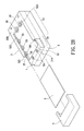
- FIG. 2B is a schematic view showing the second embodiment of the glass supporting device of a scanner in the present invention.
- the glass supporting device of a scanner of the present invention includes an upper cover 1 , a lower cover 2 , a glass sheet 3 , and a front cover 4 .
- the upper cover 1 is fixed to the upper end of the lower cover 2 .
- the two covers can be assembled as a hollow housing 5 .
- the housing 5 includes a front end portion 51 and a rear end portion 52 .
- the front end portion 51 and the rear end portion 52 of the housing 5 have a shape, are coupled with one another and are integrally formed.
- the top of the housing is formed with a rectangular via hole 53 .
- the edge frame of the front end portion 51 of the housing 5 has a top installed with two returning stop tenons 511 .
- At the connection between two sides of the edge frame 510 at the top of the front end portion 51 and the rear end portion 52 are installed with a respective sliding track 51 .
- the cross sections of edge frame 520 at the top of the rear end portion 52 and the edge frame 510 of the top of the front end portion 51 have a shape.
- At the connection of the front end portion 51 and the rear end portion 52 has a shape slit 521 .
- the size of the slit 521 is exactly suitable to be tightly matched to the thickness of the glass sheet 3 .
- the inner edges at two sides of the rear end portion 52 are installed with a sliding track 55 a plurality of protrusions.
- a shape slit 522 is formed between the sliding track 55 and the edge frame 521 of the top of the slit 522 .
- the size of the slit 522 is exactly suitable to the thickness of the glass sheet 3 .
- the height of the sliding track 55 is flushed with the sliding track 55 at the front end portion 51 .
- the lower edge of the edge frame 52 at the top of the rear end portion 52 is installed with an L shape sliding track 56 .
- the sliding track 56 and the edge frame 520 of the top of the rear end portion 52 is formed with a shape slit 523 .
- the size of each slit 523 is exactly suitable for the thickness of the glass sheet 3 .
- the slits 521 , 522 , and 523 of each sliding track 54 , 55 and 56 are installed as a sliding track 57 so as to be slid by the glass sheet 3 to be fixed therein.
- the front end portions of the sliding tracks 54 , 55 and 56 are installed with a respective slop portion 58 for guiding. Thereby, the glass sheet 3 can be easily embedded into the track 57 .
- the glass sheet 3 In assembling, the glass sheet 3 can slid into the track 57 for positioning, and then after passing through the tenons 511 , the glass sheet can be completely fixed in the top of the upper cover 1 of the housing 5 , and thus the front cover 4 is embedded into the front end portion 51 of the housing 5 so as to be assembled with a complete housing and to present a beautiful outlook. Furthermore, when detaching, the front cover 4 can be taken out easily. It is only needed to depress the tenons 511 , the glass sheet can be retracted for being detached.
- the second embodiment of the glass supporting device of a scanner according to the present invention is illustrated.
- the upper cover 1 is installed with a front end portion 51 and the rear end portion 52 .
- the glass sheet 3 is directly slid into the track 57 of the upper cover 1 and fixed therein.
- the upper cover 4 is embedded into the front end portion 51 of the upper cover 1 . Then, they are completely coupled with one another.
- the glass supporting device of a scanner of the present invention has the following advantages:
- the glass sheet can be assembled easily, and the glass sheet can be slid into the track manually.
- Repairing time is shortened. The times for covering the glass sheet and repairing parts for updating a destroyed upper cover are saved.
- the prior art assembly way for adhering a double face tape to the glass sheet is unnecessary. Therefore, the assembly and detaching are easily, and the cost for assembling parts is decreased. Moreover, the quality of the products is improved.
Abstract
Description
Claims (6)
Priority Applications (1)
| Application Number | Priority Date | Filing Date | Title |
|---|---|---|---|
| US09/667,584 US6829065B1 (en) | 2000-09-22 | 2000-09-22 | Glass supporting device of scanner |
Applications Claiming Priority (1)
| Application Number | Priority Date | Filing Date | Title |
|---|---|---|---|
| US09/667,584 US6829065B1 (en) | 2000-09-22 | 2000-09-22 | Glass supporting device of scanner |
Publications (1)
| Publication Number | Publication Date |
|---|---|
| US6829065B1 true US6829065B1 (en) | 2004-12-07 |
Family
ID=33477214
Family Applications (1)
| Application Number | Title | Priority Date | Filing Date |
|---|---|---|---|
| US09/667,584 Expired - Fee Related US6829065B1 (en) | 2000-09-22 | 2000-09-22 | Glass supporting device of scanner |
Country Status (1)
| Country | Link |
|---|---|
| US (1) | US6829065B1 (en) |
Cited By (5)
| Publication number | Priority date | Publication date | Assignee | Title |
|---|---|---|---|---|
| US20040001235A1 (en) * | 2002-06-26 | 2004-01-01 | Chien-Liang Yeh | Shock-absorber structure for scanning apparatus |
| US20040207888A1 (en) * | 2003-04-18 | 2004-10-21 | Michael Grecco | Glass plate film holder for scanners |
| US20130135690A1 (en) * | 2010-02-11 | 2013-05-30 | Burkhard Soehler | Device for reproducing images that can be found on originals |
| US8641000B1 (en) * | 2008-09-10 | 2014-02-04 | Frances W. Eide | Tile holder and methods of use |
| US20200036854A1 (en) * | 2018-07-30 | 2020-01-30 | Canon Kabushiki Kaisha | Image reading device |
Citations (1)
| Publication number | Priority date | Publication date | Assignee | Title |
|---|---|---|---|---|
| JP2003201791A (en) * | 2001-10-30 | 2003-07-18 | Asahi Kasei Corp | Structure for opening and structural member of fittings |
-
2000
- 2000-09-22 US US09/667,584 patent/US6829065B1/en not_active Expired - Fee Related
Patent Citations (1)
| Publication number | Priority date | Publication date | Assignee | Title |
|---|---|---|---|---|
| JP2003201791A (en) * | 2001-10-30 | 2003-07-18 | Asahi Kasei Corp | Structure for opening and structural member of fittings |
Cited By (12)
| Publication number | Priority date | Publication date | Assignee | Title |
|---|---|---|---|---|
| US20040001235A1 (en) * | 2002-06-26 | 2004-01-01 | Chien-Liang Yeh | Shock-absorber structure for scanning apparatus |
| US7382504B2 (en) * | 2002-06-26 | 2008-06-03 | Transpacific Ip, Ltd. | Shock-absorber structure for scanning apparatus |
| US20040207888A1 (en) * | 2003-04-18 | 2004-10-21 | Michael Grecco | Glass plate film holder for scanners |
| US7508556B2 (en) * | 2003-04-18 | 2009-03-24 | Michael Grecco | Glass plate film holder for scanners |
| US8641000B1 (en) * | 2008-09-10 | 2014-02-04 | Frances W. Eide | Tile holder and methods of use |
| US20130135690A1 (en) * | 2010-02-11 | 2013-05-30 | Burkhard Soehler | Device for reproducing images that can be found on originals |
| US8743429B2 (en) * | 2010-02-11 | 2014-06-03 | Roth + Weber Gmbh | Device for reproducing images that can be found on originals |
| US20200036854A1 (en) * | 2018-07-30 | 2020-01-30 | Canon Kabushiki Kaisha | Image reading device |
| CN110784617A (en) * | 2018-07-30 | 2020-02-11 | 佳能株式会社 | Image reading apparatus |
| US10805500B2 (en) * | 2018-07-30 | 2020-10-13 | Canon Kabushiki Kaisha | Image reading device |
| CN110784617B (en) * | 2018-07-30 | 2022-04-19 | 佳能株式会社 | Image reading apparatus |
| EP3614657B1 (en) * | 2018-07-30 | 2022-11-30 | Canon Kabushiki Kaisha | Image reading device |
Similar Documents
| Publication | Publication Date | Title |
|---|---|---|
| RU2543505C2 (en) | Electrical lead | |
| US8213182B2 (en) | Housing case for housing electronic circuit board, and electronic apparatus | |
| US6829065B1 (en) | Glass supporting device of scanner | |
| US7423788B2 (en) | Image scanner | |
| US8247707B2 (en) | Shielding assembly | |
| US20110075348A1 (en) | Mounting apparatus for disk drive | |
| US20080090511A1 (en) | Mounting apparatus for fan | |
| US20060180448A1 (en) | Electronic apparatus with operation button | |
| US10901000B2 (en) | Electrical testing jig | |
| US7538915B2 (en) | Book scanner with a minimized scan margin | |
| JP2009017574A (en) | Image read apparatus | |
| US20060284712A1 (en) | Isolating cover | |
| CN100487531C (en) | Combined structure and its assembling method | |
| US20030076552A1 (en) | Contact image sensor (CIS) | |
| US20080030652A1 (en) | System for displaying image | |
| KR102298540B1 (en) | Fixing apparatus of lens holder | |
| US5969245A (en) | Scanner casing | |
| CN213601133U (en) | Customized case capable of being assembled quickly | |
| US6424390B1 (en) | Liquid crystal display panel structure | |
| CN106657710B (en) | Frame assembly and contact type image sensor with same | |
| JP4235585B2 (en) | Image reading device | |
| CN110737045A (en) | backlight module and electronic equipment | |
| US7445151B2 (en) | Card printer with a dust-proof card receiver | |
| CN220498980U (en) | Auxiliary assembly fixture for LED display screen | |
| KR200389047Y1 (en) | Liquid crystal display module |
Legal Events
| Date | Code | Title | Description |
|---|---|---|---|
| AS | Assignment |
Owner name: SILITEK CORPORATION, TAIWAN Free format text: ASSIGNMENT OF ASSIGNORS INTEREST;ASSIGNORS:LEE, TA-YI;HUNG, MING-TE;CHEN, LUNG;AND OTHERS;REEL/FRAME:011135/0369 Effective date: 20000914 |
|
| AS | Assignment |
Owner name: LITE-ON TECHNOLOGY CORPORATION, TAIWAN Free format text: MERGER;ASSIGNOR:SILITEK CORP.;REEL/FRAME:013887/0400 Effective date: 20021113 |
|
| AS | Assignment |
Owner name: GUAN TECHNOLOGIES, LLC, DELAWARE Free format text: ASSIGNMENT OF ASSIGNORS INTEREST;ASSIGNOR:LITE-ON TECHNOLOGY CORP.;REEL/FRAME:020317/0552 Effective date: 20071218 Owner name: GUAN TECHNOLOGIES, LLC,DELAWARE Free format text: ASSIGNMENT OF ASSIGNORS INTEREST;ASSIGNOR:LITE-ON TECHNOLOGY CORP.;REEL/FRAME:020317/0552 Effective date: 20071218 |
|
| AS | Assignment |
Owner name: GUAN TECHNOLOGIES, LLC, DELAWARE Free format text: ASSIGNMENT OF ASSIGNORS INTEREST;ASSIGNOR:LITE-ON TECHNOLOGY CORP.;REEL/FRAME:020403/0630 Effective date: 20071218 Owner name: GUAN TECHNOLOGIES, LLC,DELAWARE Free format text: ASSIGNMENT OF ASSIGNORS INTEREST;ASSIGNOR:LITE-ON TECHNOLOGY CORP.;REEL/FRAME:020403/0630 Effective date: 20071218 |
|
| FPAY | Fee payment |
Year of fee payment: 4 |
|
| REMI | Maintenance fee reminder mailed | ||
| LAPS | Lapse for failure to pay maintenance fees | ||
| STCH | Information on status: patent discontinuation |
Free format text: PATENT EXPIRED DUE TO NONPAYMENT OF MAINTENANCE FEES UNDER 37 CFR 1.362 |
|
| FP | Lapsed due to failure to pay maintenance fee |
Effective date: 20121207 |