US6824303B2 - Apparatus for blending and making ice cream - Google Patents
Apparatus for blending and making ice cream Download PDFInfo
- Publication number
- US6824303B2 US6824303B2 US10/404,390 US40439003A US6824303B2 US 6824303 B2 US6824303 B2 US 6824303B2 US 40439003 A US40439003 A US 40439003A US 6824303 B2 US6824303 B2 US 6824303B2
- Authority
- US
- United States
- Prior art keywords
- unit
- speed
- engaging hole
- blending
- removably
- Prior art date
- Legal status (The legal status is an assumption and is not a legal conclusion. Google has not performed a legal analysis and makes no representation as to the accuracy of the status listed.)
- Expired - Fee Related, expires
Links
- 238000002156 mixing Methods 0.000 title claims abstract description 39
- 235000015243 ice cream Nutrition 0.000 title claims abstract description 23
- 238000003756 stirring Methods 0.000 claims abstract description 33
- 230000008878 coupling Effects 0.000 claims description 14
- 238000010168 coupling process Methods 0.000 claims description 14
- 238000005859 coupling reaction Methods 0.000 claims description 14
- 239000003507 refrigerant Substances 0.000 claims description 3
- 235000011389 fruit/vegetable juice Nutrition 0.000 claims 1
- 235000013305 food Nutrition 0.000 description 3
- 239000000463 material Substances 0.000 description 3
- 235000013399 edible fruits Nutrition 0.000 description 1
- 238000000034 method Methods 0.000 description 1
- 238000012986 modification Methods 0.000 description 1
- 230000004048 modification Effects 0.000 description 1
- 235000013311 vegetables Nutrition 0.000 description 1
Images


Classifications
-
- A—HUMAN NECESSITIES
- A23—FOODS OR FOODSTUFFS; TREATMENT THEREOF, NOT COVERED BY OTHER CLASSES
- A23G—COCOA; COCOA PRODUCTS, e.g. CHOCOLATE; SUBSTITUTES FOR COCOA OR COCOA PRODUCTS; CONFECTIONERY; CHEWING GUM; ICE-CREAM; PREPARATION THEREOF
- A23G9/00—Frozen sweets, e.g. ice confectionery, ice-cream; Mixtures therefor
- A23G9/04—Production of frozen sweets, e.g. ice-cream
- A23G9/08—Batch production
- A23G9/12—Batch production using means for stirring the contents in a non-moving container
-
- A—HUMAN NECESSITIES
- A23—FOODS OR FOODSTUFFS; TREATMENT THEREOF, NOT COVERED BY OTHER CLASSES
- A23G—COCOA; COCOA PRODUCTS, e.g. CHOCOLATE; SUBSTITUTES FOR COCOA OR COCOA PRODUCTS; CONFECTIONERY; CHEWING GUM; ICE-CREAM; PREPARATION THEREOF
- A23G9/00—Frozen sweets, e.g. ice confectionery, ice-cream; Mixtures therefor
- A23G9/04—Production of frozen sweets, e.g. ice-cream
- A23G9/22—Details, component parts or accessories of apparatus insofar as not peculiar to a single one of the preceding groups
- A23G9/224—Agitators or scrapers
-
- A—HUMAN NECESSITIES
- A23—FOODS OR FOODSTUFFS; TREATMENT THEREOF, NOT COVERED BY OTHER CLASSES
- A23G—COCOA; COCOA PRODUCTS, e.g. CHOCOLATE; SUBSTITUTES FOR COCOA OR COCOA PRODUCTS; CONFECTIONERY; CHEWING GUM; ICE-CREAM; PREPARATION THEREOF
- A23G9/00—Frozen sweets, e.g. ice confectionery, ice-cream; Mixtures therefor
- A23G9/04—Production of frozen sweets, e.g. ice-cream
- A23G9/22—Details, component parts or accessories of apparatus insofar as not peculiar to a single one of the preceding groups
- A23G9/225—Ice-cream freezing and storing cabinets
-
- B—PERFORMING OPERATIONS; TRANSPORTING
- B01—PHYSICAL OR CHEMICAL PROCESSES OR APPARATUS IN GENERAL
- B01F—MIXING, e.g. DISSOLVING, EMULSIFYING OR DISPERSING
- B01F27/00—Mixers with rotary stirring devices in fixed receptacles; Kneaders
- B01F27/80—Mixers with rotary stirring devices in fixed receptacles; Kneaders with stirrers rotating about a substantially vertical axis
- B01F27/805—Mixers with rotary stirring devices in fixed receptacles; Kneaders with stirrers rotating about a substantially vertical axis wherein the stirrers or the receptacles are moved in order to bring them into operative position; Means for fixing the receptacle
-
- B—PERFORMING OPERATIONS; TRANSPORTING
- B01—PHYSICAL OR CHEMICAL PROCESSES OR APPARATUS IN GENERAL
- B01F—MIXING, e.g. DISSOLVING, EMULSIFYING OR DISPERSING
- B01F35/00—Accessories for mixers; Auxiliary operations or auxiliary devices; Parts or details of general application
- B01F35/30—Driving arrangements; Transmissions; Couplings; Brakes
- B01F35/32—Driving arrangements
-
- B—PERFORMING OPERATIONS; TRANSPORTING
- B01—PHYSICAL OR CHEMICAL PROCESSES OR APPARATUS IN GENERAL
- B01F—MIXING, e.g. DISSOLVING, EMULSIFYING OR DISPERSING
- B01F35/00—Accessories for mixers; Auxiliary operations or auxiliary devices; Parts or details of general application
- B01F35/30—Driving arrangements; Transmissions; Couplings; Brakes
- B01F35/33—Transmissions; Means for modifying the speed or direction of rotation
- B01F35/331—Transmissions; Means for modifying the speed or direction of rotation alternately changing the speed of rotation
Definitions
- the invention relates to a food processing apparatus, more particularly to an apparatus suitable for blending and for making ice cream.
- a conventional ice cream making machine includes a stand 1 , a refrigerant container unit 2 mounted on top of the stand 1 , a drive unit 3 mounted on top of the container unit 2 , and a stirring unit 4 coupled to and driven by the drive unit 3 .
- the requirements of keeping the container unit 2 at a low temperature and low-speed stirring by the stirring unit 4 are essential for ice cream making.
- the container unit 2 includes an inner barrel 201 for receiving material for making ice cream, and the drive unit 3 is operable so as to enable the stirring unit 4 to stir the material in the inner barrel 201 at a low speed in order to slowly form the ice cream.
- a conventional blender is used to process vegetables or fruits through a blade unit thereof at a relatively high speed.
- the aforesaid ice cream making machine and blender operate at two different speeds, thereby providing entirely different food processing functionalities. As such, consumers must purchase an ice cream making machine and a blender individually to have both blending and ice cream making effects.
- the object of the present invention is to provide a single apparatus suitable for blending and for making ice cream.
- an apparatus for blending and for making ice cream of this invention comprises a drive unit, and a blending unit and a stirring unit that selectively and removably engage the drive unit.
- the drive unit includes a casing, a motor mounted in the casing, a drive shaft disposed in the casing and coupled to and driven rotatably by the motor, and a high-speed output gear unit, a speed-reduction gear unit, and a low-speed output gear unit disposed in the casing.
- the high-speed output gear unit is coupled directly to and is driven rotatably by the drive shaft, and is formed with a first engaging hole that extends along a rotary axis.
- the speed-reduction gear unit is coupled to and is driven rotatably by the drive shaft.
- the low-speed output gear unit is coupled to and is driven rotatably by the speed-reduction gear unit, and is formed with a second engaging hole that is coaxial with the first engaging hole.
- the casing is formed with an insert hole that is registered with the first and second engaging holes.
- the blending unit includes a blending axle having a mounting end inserted removably into the insert hole and configured to engage removably the first engaging hole in the high-speed output gear unit, and an opposite end mounted with a blade set.
- the blending unit is driven by the drive unit to rotate about the rotary axis at a first speed when coupled to the high-speed output gear unit.
- the stirring unit includes a stirring axle having a mounting end inserted removably into the insert hole and configured to engage removably the second engaging hole in the low-speed output gear unit, and a stirring paddle set mounted on the stirring axle.
- the stirring unit is driven by the drive unit to rotate about the rotary axis at a second speed slower than the first speed when coupled to the low-speed output gear unit.
- FIG. 1 is a schematic, partly sectional view of a conventional ice cream making machine
- FIG. 2 is an exploded, schematic, partly sectional view of the preferred embodiment of an apparatus for blending and for making ice cream according to the present invention
- FIG. 3 is a schematic cross-sectional view taken along line 3 — 3 of FIG. 2;
- FIG. 4 is an exploded perspective view illustrating a bevel gear and a blending unit of the preferred embodiment
- FIG. 5 is a partly assembled, perspective view illustrating a first container device and a drive unit of the preferred embodiment
- FIG. 6 is a schematic, partly sectional view of the preferred embodiment when used for blending
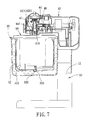
- FIG. 7 is a schematic, partly sectional view of the preferred embodiment when used for making ice cream.
- FIG. 8 is a schematic, cross-sectional view taken along line 8 — 8 of FIG. 6 .
- an apparatus for blending and for making ice cream is shown to include a stand 10 , a first container device 20 and a second container device 30 that can be mounted selectively and removably on top of the stand 10 , a drive unit 40 that can be mounted on top of either the first container device 20 or the second container device 30 , and a blending unit 50 and a stirring unit 60 that can be selectively and removably coupled to the drive unit 40 .
- the stand 10 has a bottom section 11 to be placed on a table surface, and a top section 12 opposite to the bottom section 11 .
- a coupling post 121 extends uprightly from the top section 12 of the stand 10 .
- the first container device 20 is used when the apparatus is operated in a blending mode, and includes a coupling member 21 sleeved removably on the coupling post 121 at the top section 12 of the stand 10 , and a container 22 connected removably to the coupling member 21 .
- the coupling member 21 has a lateral side with an L-shaped hook member 211 protruding therefrom, and a top portion provided with a pair of fastening members 212 .
- the container 22 has an outer wall surface formed with an inverted L-shaped fastener 221 to interlock removably with the hook member 211 .
- the second container device 30 is used when the apparatus is operated in an ice cream making mode, and includes a coupling member 31 sleeved removably on the coupling post 121 at the top section 12 of the stand 10 , and a container unit 32 .
- the container unit 32 includes an outer barrel 321 connected fixedly to the coupling member 31 , an inner barrel 322 disposed in the outer barrel 321 and cooperating with the outer barrel 321 to confine a sealed space for receiving a refrigerant 323 therein, and a cover (not shown) for covering an open top side of the outer barrel 321 .
- the inner barrel 322 has a bottom wall formed with a central recess 325 .
- the drive unit 40 includes a casing 41 mounted removably on either one of the coupling members 21 , 31 , a motor 42 mounted in the casing 41 , a horizontally extending drive shaft 43 disposed in the casing 41 and coupled to and driven rotatably by the motor 42 , a high-speed output gear unit 44 disposed in the casing 41 and coupled directly to and driven rotatably by the drive shaft 43 , a speed-reduction gear unit 45 disposed in the casing 41 and coupled to and driven rotatably by the drive shaft 43 , and a low-speed output gear unit 46 disposed in the casing 41 and coupled to and driven rotatably by the speed-reduction gear unit 45 .
- the casing 41 can be locked removably to the coupling member 21 in a known manner through the fastening members 212 .
- the high-speed output gear unit 44 includes a first bevel gear 441 mounted on one end of the drive shaft 43 , and a second bevel gear 442 disposed rotatably in the casing 41 and meshing with the first bevel gear 441 .
- the second bevel gear 442 is formed with a first engaging hole 443 that extends along a rotary axis (L) transverse to the drive shaft 43 , and has a hole-defining surface 444 that defines the first engaging hole 443 .
- the hole-defining surface 444 is formed with a pair of axially extending slide grooves 445 and a pair of radially extending engaging grooves 446 that intersect the slide grooves 445 , respectively.
- the speed-reduction gear unit 45 includes a worm section 431 formed directly on the drive shaft 43 , a worm gear 451 meshing with the worm section 431 , and a speed-reduction gear set 452 meshing with the worm gear 451 and the low-speed output gear unit 46 .
- the low-speed output gear unit 46 is formed with a second engaging hole 461 that is coaxial with the first engaging hole 443 , and has a hole-defining surface 462 that defines the second engaging hole 461 .
- the second engaging hole 461 is disposed below the first engaging hole 443 relative to the rotary axis (L), and has a larger diameter than the first engaging hole 443 .
- the arrangement as such results in a compact structure for the drive unit 40 .
- the hole-defining surface 462 is formed with a plurality of axially extending splines 463 .
- the casing 41 has a bottom wall formed with an insert hole 410 (see FIG. 2) that is registered with the first and second engaging holes 443 , 461 .
- the blending unit 50 is used together with the first container device 20 when the apparatus is operated in the blending mode, and includes a blending axle 51 having a mounting end inserted removably into the insert hole 410 and configured to engage removably the first engaging hole 443 in the high-speed output gear unit 44 , and an opposite end mounted with a blade set 52 that is to be extended into the container 22 .
- the mounting end of the blending axle 51 is formed with a pair of radial key projections 511 , each of which is slidable along a respective one of the slide grooves 445 and into a respective one of the engaging grooves 446 so as to couple removably the blending unit 50 to the second bevel gear 442 of the high-speed output gear unit 44 .
- the blending unit 50 can be driven by the drive unit 40 to rotate about the rotary axis (L) at a first speed when coupled to the high-speed output gear unit 44 .
- the stirring unit 60 is used together with the second container device 30 when the apparatus is operated in the ice cream making mode, and includes a stirring axle 61 having a mounting end inserted removably into the insert hole 410 and configured to engage removably the second engaging hole 461 in the low-speed output gear unit 46 , and a stirring paddle set 62 , in the form of a hollow frame, mounted on the stirring axle 61 .
- the mounting end of the stirring axle 61 is formed as a splined shaft 611 that engages the splines 463 in the second engaging hole 461 of the low-speed output gear unit 46 .
- the stirring unit 60 can be driven by the drive unit 40 to rotate about the rotary axis (L) at a second speed slower than the first speed when coupled to the low-speed output gear unit 46 .
- the stirring paddle set 62 is to be disposed in the inner barrel 322 , and has a bottom part formed with a stub 621 that is to be disposed in the central recess 325 .
- the first container device 20 is mounted on the stand 10 , and the drive unit 40 is connected to the first container device 20 .
- the blending unit 50 is then connected to the drive unit 40 in the manner described hereinabove. Because the second engaging hole 461 is larger than the first engaging hole 443 , engagement between the mounting end of the blending axle 51 and the first engaging hole 443 will not be hindered by the second engaging hole 443 .
- the drive shaft 43 drives directly the first bevel gear 441 , and the second bevel gear 442 and the blending unit 50 are driven in turn to rotate about the rotary axis (L) at the first speed, such as 20000 rpm, so that food in the container 22 of the first container device 20 will be processed by the blade set 52 of the blending unit 50 .
- the fastening members 212 ensure firm engagement between the drive unit 40 and the first container device 20 when the apparatus is operated in the blending mode.
- the second container device 30 is mounted on the stand 10 , and the drive unit 40 is mounted on the second container device 30 .
- the stirring unit 60 is then connected to the drive unit 40 in the manner described hereinabove.
- the drive shaft 43 drives the stirring unit 60 through the speed-reduction gear unit 45 and the low-speed output gear unit 46 so as to rotate about the rotary axis (L) at the second speed, such as 60 rpm, and so that the stirring paddle set 62 can stir material in the inner barrel 322 to form ice cream in a conventional manner.
- the high-speed output gear unit 44 does not engage the stirring unit 60 . Therefore, the high-speed output gear unit 44 rotates idly at this time.
- the apparatus of this invention combines the functionalities of a blender and an ice cream making apparatus into a single machine, thereby resulting in convenience and cost savings for consumers.
Landscapes
- Chemical & Material Sciences (AREA)
- Engineering & Computer Science (AREA)
- Life Sciences & Earth Sciences (AREA)
- Food Science & Technology (AREA)
- Polymers & Plastics (AREA)
- Chemical Kinetics & Catalysis (AREA)
- Manufacturing & Machinery (AREA)
- Food-Manufacturing Devices (AREA)
- Confectionery (AREA)
Abstract
An apparatus for blending and for making ice cream includes drive, blending, and stirring units. The drive unit includes a high-speed output gear unit driven rotatably by a drive shaft and formed with a first engaging hole that extends along a rotary axis, a speed-reduction gear unit driven rotatably by the drive shaft, and a low-speed output gear unit driven rotatably by the speed-reduction gear unit and formed with a second engaging hole that is coaxial with the first engaging hole. The blending unit engages removably the first engaging hole and is driven by the drive unit to rotate about the rotary axis at a higher speed. The stirring unit engages removably the second engaging hole and is driven by the drive unit to rotate about the rotary axis at a lower speed.
Description
This application claims priority of Taiwanese application no. 092200986, filed on Jan. 20, 2003.
1. Field of the Invention
The invention relates to a food processing apparatus, more particularly to an apparatus suitable for blending and for making ice cream.
2. Description of the Related Art
As shown in FIG. 1, a conventional ice cream making machine includes a stand 1, a refrigerant container unit 2 mounted on top of the stand 1, a drive unit 3 mounted on top of the container unit 2, and a stirring unit 4 coupled to and driven by the drive unit 3. The requirements of keeping the container unit 2 at a low temperature and low-speed stirring by the stirring unit 4 are essential for ice cream making. Accordingly, the container unit 2 includes an inner barrel 201 for receiving material for making ice cream, and the drive unit 3 is operable so as to enable the stirring unit 4 to stir the material in the inner barrel 201 at a low speed in order to slowly form the ice cream.
On the other hand, a conventional blender is used to process vegetables or fruits through a blade unit thereof at a relatively high speed.
The aforesaid ice cream making machine and blender operate at two different speeds, thereby providing entirely different food processing functionalities. As such, consumers must purchase an ice cream making machine and a blender individually to have both blending and ice cream making effects.
Therefore, the object of the present invention is to provide a single apparatus suitable for blending and for making ice cream.
Accordingly, an apparatus for blending and for making ice cream of this invention comprises a drive unit, and a blending unit and a stirring unit that selectively and removably engage the drive unit.
The drive unit includes a casing, a motor mounted in the casing, a drive shaft disposed in the casing and coupled to and driven rotatably by the motor, and a high-speed output gear unit, a speed-reduction gear unit, and a low-speed output gear unit disposed in the casing. The high-speed output gear unit is coupled directly to and is driven rotatably by the drive shaft, and is formed with a first engaging hole that extends along a rotary axis. The speed-reduction gear unit is coupled to and is driven rotatably by the drive shaft. The low-speed output gear unit is coupled to and is driven rotatably by the speed-reduction gear unit, and is formed with a second engaging hole that is coaxial with the first engaging hole. The casing is formed with an insert hole that is registered with the first and second engaging holes.
The blending unit includes a blending axle having a mounting end inserted removably into the insert hole and configured to engage removably the first engaging hole in the high-speed output gear unit, and an opposite end mounted with a blade set. The blending unit is driven by the drive unit to rotate about the rotary axis at a first speed when coupled to the high-speed output gear unit.
The stirring unit includes a stirring axle having a mounting end inserted removably into the insert hole and configured to engage removably the second engaging hole in the low-speed output gear unit, and a stirring paddle set mounted on the stirring axle. The stirring unit is driven by the drive unit to rotate about the rotary axis at a second speed slower than the first speed when coupled to the low-speed output gear unit.
Other features and advantages of the present invention will become apparent in the following detailed description of the preferred embodiment with reference to the accompanying drawings, of which:
FIG. 1 is a schematic, partly sectional view of a conventional ice cream making machine;
FIG. 2 is an exploded, schematic, partly sectional view of the preferred embodiment of an apparatus for blending and for making ice cream according to the present invention;
FIG. 3 is a schematic cross-sectional view taken along line 3—3 of FIG. 2;
FIG. 4 is an exploded perspective view illustrating a bevel gear and a blending unit of the preferred embodiment;
FIG. 5 is a partly assembled, perspective view illustrating a first container device and a drive unit of the preferred embodiment;
FIG. 6 is a schematic, partly sectional view of the preferred embodiment when used for blending;
FIG. 7 is a schematic, partly sectional view of the preferred embodiment when used for making ice cream; and
FIG. 8 is a schematic, cross-sectional view taken along line 8—8 of FIG. 6.
Referring to FIG. 2, the preferred embodiment of an apparatus for blending and for making ice cream according to the present invention is shown to include a stand 10, a first container device 20 and a second container device 30 that can be mounted selectively and removably on top of the stand 10, a drive unit 40 that can be mounted on top of either the first container device 20 or the second container device 30, and a blending unit 50 and a stirring unit 60 that can be selectively and removably coupled to the drive unit 40.
The stand 10 has a bottom section 11 to be placed on a table surface, and a top section 12 opposite to the bottom section 11. A coupling post 121 extends uprightly from the top section 12 of the stand 10.
With reference to FIGS. 2, 5 and 6, the first container device 20 is used when the apparatus is operated in a blending mode, and includes a coupling member 21 sleeved removably on the coupling post 121 at the top section 12 of the stand 10, and a container 22 connected removably to the coupling member 21. The coupling member 21 has a lateral side with an L-shaped hook member 211 protruding therefrom, and a top portion provided with a pair of fastening members 212. The container 22 has an outer wall surface formed with an inverted L-shaped fastener 221 to interlock removably with the hook member 211.
Referring to FIGS. 2 and 7, the second container device 30 is used when the apparatus is operated in an ice cream making mode, and includes a coupling member 31 sleeved removably on the coupling post 121 at the top section 12 of the stand 10, and a container unit 32. The container unit 32 includes an outer barrel 321 connected fixedly to the coupling member 31, an inner barrel 322 disposed in the outer barrel 321 and cooperating with the outer barrel 321 to confine a sealed space for receiving a refrigerant 323 therein, and a cover (not shown) for covering an open top side of the outer barrel 321. The inner barrel 322 has a bottom wall formed with a central recess 325.
Referring to FIGS. 2 and 3, the drive unit 40 includes a casing 41 mounted removably on either one of the coupling members 21, 31, a motor 42 mounted in the casing 41, a horizontally extending drive shaft 43 disposed in the casing 41 and coupled to and driven rotatably by the motor 42, a high-speed output gear unit 44 disposed in the casing 41 and coupled directly to and driven rotatably by the drive shaft 43, a speed-reduction gear unit 45 disposed in the casing 41 and coupled to and driven rotatably by the drive shaft 43, and a low-speed output gear unit 46 disposed in the casing 41 and coupled to and driven rotatably by the speed-reduction gear unit 45. In this embodiment, the casing 41 can be locked removably to the coupling member 21 in a known manner through the fastening members 212. The high-speed output gear unit 44 includes a first bevel gear 441 mounted on one end of the drive shaft 43, and a second bevel gear 442 disposed rotatably in the casing 41 and meshing with the first bevel gear 441. The second bevel gear 442 is formed with a first engaging hole 443 that extends along a rotary axis (L) transverse to the drive shaft 43, and has a hole-defining surface 444 that defines the first engaging hole 443. With further reference to FIG. 4, in this embodiment, the hole-defining surface 444 is formed with a pair of axially extending slide grooves 445 and a pair of radially extending engaging grooves 446 that intersect the slide grooves 445, respectively. As best shown in FIG. 3, the speed-reduction gear unit 45 includes a worm section 431 formed directly on the drive shaft 43, a worm gear 451 meshing with the worm section 431, and a speed-reduction gear set 452 meshing with the worm gear 451 and the low-speed output gear unit 46. Referring once again to FIG. 2, the low-speed output gear unit 46 is formed with a second engaging hole 461 that is coaxial with the first engaging hole 443, and has a hole-defining surface 462 that defines the second engaging hole 461. In this embodiment, the second engaging hole 461 is disposed below the first engaging hole 443 relative to the rotary axis (L), and has a larger diameter than the first engaging hole 443. The arrangement as such results in a compact structure for the drive unit 40. The hole-defining surface 462 is formed with a plurality of axially extending splines 463. In addition, the casing 41 has a bottom wall formed with an insert hole 410 (see FIG. 2) that is registered with the first and second engaging holes 443, 461.
Referring to FIGS. 4 and 6, the blending unit 50 is used together with the first container device 20 when the apparatus is operated in the blending mode, and includes a blending axle 51 having a mounting end inserted removably into the insert hole 410 and configured to engage removably the first engaging hole 443 in the high-speed output gear unit 44, and an opposite end mounted with a blade set 52 that is to be extended into the container 22. In this embodiment, the mounting end of the blending axle 51 is formed with a pair of radial key projections 511, each of which is slidable along a respective one of the slide grooves 445 and into a respective one of the engaging grooves 446 so as to couple removably the blending unit 50 to the second bevel gear 442 of the high-speed output gear unit 44. Accordingly, the blending unit 50 can be driven by the drive unit 40 to rotate about the rotary axis (L) at a first speed when coupled to the high-speed output gear unit 44.
As shown in FIGS. 2 and 7, the stirring unit 60 is used together with the second container device 30 when the apparatus is operated in the ice cream making mode, and includes a stirring axle 61 having a mounting end inserted removably into the insert hole 410 and configured to engage removably the second engaging hole 461 in the low-speed output gear unit 46, and a stirring paddle set 62, in the form of a hollow frame, mounted on the stirring axle 61. The mounting end of the stirring axle 61 is formed as a splined shaft 611 that engages the splines 463 in the second engaging hole 461 of the low-speed output gear unit 46. Thus, the stirring unit 60 can be driven by the drive unit 40 to rotate about the rotary axis (L) at a second speed slower than the first speed when coupled to the low-speed output gear unit 46. The stirring paddle set 62 is to be disposed in the inner barrel 322, and has a bottom part formed with a stub 621 that is to be disposed in the central recess 325.
Referring to FIGS. 6 and 8, to operate the apparatus in the blending mode, the first container device 20 is mounted on the stand 10, and the drive unit 40 is connected to the first container device 20. The blending unit 50 is then connected to the drive unit 40 in the manner described hereinabove. Because the second engaging hole 461 is larger than the first engaging hole 443, engagement between the mounting end of the blending axle 51 and the first engaging hole 443 will not be hindered by the second engaging hole 443. When the motor 42 is activated, the drive shaft 43 drives directly the first bevel gear 441, and the second bevel gear 442 and the blending unit 50 are driven in turn to rotate about the rotary axis (L) at the first speed, such as 20000 rpm, so that food in the container 22 of the first container device 20 will be processed by the blade set 52 of the blending unit 50. The fastening members 212 ensure firm engagement between the drive unit 40 and the first container device 20 when the apparatus is operated in the blending mode.
During the aforesaid blending operation, it is noted that the low-speed output gear unit 46 does not engage the blending unit 50. Therefore, the speed-reduction gear unit 45 and the low-speed output gear unit 46 rotate idly at this time.
As shown in FIG. 7, to operate the apparatus in the ice cream making mode, the second container device 30 is mounted on the stand 10, and the drive unit 40 is mounted on the second container device 30. The stirring unit 60 is then connected to the drive unit 40 in the manner described hereinabove. When the motor 42 is activated, the drive shaft 43 drives the stirring unit 60 through the speed-reduction gear unit 45 and the low-speed output gear unit 46 so as to rotate about the rotary axis (L) at the second speed, such as 60 rpm, and so that the stirring paddle set 62 can stir material in the inner barrel 322 to form ice cream in a conventional manner.
During the aforesaid ice cream making operation, it is noted that the high-speed output gear unit 44 does not engage the stirring unit 60. Therefore, the high-speed output gear unit 44 rotates idly at this time.
In summary, the apparatus of this invention combines the functionalities of a blender and an ice cream making apparatus into a single machine, thereby resulting in convenience and cost savings for consumers.
While the present invention has been described in connection with what is considered the most practical and preferred embodiment, it is understood that this invention is not limited to the disclosed embodiment but is intended to cover various arrangements included within the spirit and scope of the broadest interpretation so as to encompass all such modifications and equivalent arrangements.
Claims (8)
1. An apparatus for blending juice and making ice cream, comprising:
a drive unit including
a casing,
a motor mounted in said casing,
a drive shaft disposed in said casing and coupled to and driven rotatably by said motor,
a high-speed output gear unit disposed in said casing, coupled directly to and driven rotatably by said drive shaft, and formed with a first engaging hole that extends along a rotary axis,
a speed-reduction gear unit disposed in said casing and coupled to and driven rotatably by said drive shaft, and
a low-speed output gear unit disposed in said casing, coupled to and driven rotatably by said speed-reduction gear unit, and formed with a second engaging hole that is coaxial with said first engaging hole,
said casing being formed with an insert hole that is registered with said first and second engaging holes; and
a blending unit and a stirring unit that selectively and removably engage said drive unit;
said blending unit including a blending axle having a mounting end inserted removably into said insert hole and configured to engage removably said first engaging hole in said high-speed output gear unit, and an opposite end mounted with a blade set, said blending unit being driven by said drive unit to rotate about said rotary axis at a first speed when coupled to said high-speed output gear unit;
said stirring unit including a stirring axle having a mounting end inserted removably into said insert hole and configured to engage removably said second engaging hole in said low-speed output gear unit, and a stirring paddle set mounted on said stirring axle, said stirring unit being driven by said drive unit to rotate about said rotary axis at a second speed slower than the first speed when coupled to said low-speed output gear unit.
2. The apparatus as claimed in claim 1 , wherein said high-speed output gear unit includes a first bevel gear mounted on said drive shaft, and a second bevel gear meshing with said first bevel gear and formed with said first engaging hole, said second bevel gear having a hole-defining surface that defines said first engaging hole, said hole-defining surface being formed with an axially extending slide groove and a radially extending engaging groove that intersects said slide grove, said mounting end of said blending axle being formed with a radial key projection that is slidable along said slide groove and into said engaging groove so as to couple removably said blending unit to said second bevel gear.
3. The apparatus as claimed in claim 1 , wherein said mounting end of said stirring axle is formed as a splined shaft that engages removably said second engaging hole.
4. The apparatus as claimed in claim 1 , wherein said second engaging hole is disposed below said first engaging hole relative to said rotary axis and has a larger diameter than said first engaging hole.
5. The apparatus as claimed in claim 1 , wherein said speed-reduction gear unit includes a worm section on said drive shaft, a worm gear meshing with said worm section, and a speed-reduction gear set meshing with said worm gear and said low-speed output gear unit.
6. The apparatus as claimed in claim 1 , further comprising a stand having a bottom section and a top section opposite to said bottom section, and a coupling member sleeved removably on said top section of said stand, said casing being mounted removably on said coupling member.
7. The apparatus as claimed in claim 6 , further comprising a container connected removably to said coupling member.
8. The apparatus as claimed in claim 6 , further comprising a container unit that includes an outer barrel connected fixedly to said coupling member, and an inner barrel disposed in said outer barrel and cooperating with said outer barrel to confine a sealed space for receiving a refrigerant therein.
Applications Claiming Priority (3)
| Application Number | Priority Date | Filing Date | Title |
|---|---|---|---|
| TW092200986U TW588628U (en) | 2003-01-20 | 2003-01-20 | Food processor with juicing and ice-cream-making functions |
| TW92200986U | 2003-01-20 | ||
| TW092200986 | 2003-01-20 |
Publications (2)
| Publication Number | Publication Date |
|---|---|
| US20040141411A1 US20040141411A1 (en) | 2004-07-22 |
| US6824303B2 true US6824303B2 (en) | 2004-11-30 |
Family
ID=32710227
Family Applications (1)
| Application Number | Title | Priority Date | Filing Date |
|---|---|---|---|
| US10/404,390 Expired - Fee Related US6824303B2 (en) | 2003-01-20 | 2003-04-01 | Apparatus for blending and making ice cream |
Country Status (2)
| Country | Link |
|---|---|
| US (1) | US6824303B2 (en) |
| TW (1) | TW588628U (en) |
Cited By (22)
| Publication number | Priority date | Publication date | Assignee | Title |
|---|---|---|---|---|
| US20060185526A1 (en) * | 2005-02-19 | 2006-08-24 | Donglei Wong | Movable bucket and matching fixed bucket for an ice-cream machine and an ice-cream machine with said movable bucket and matching fixed bucket |
| US20110203462A1 (en) * | 2004-03-10 | 2011-08-25 | Nestec S.A. | Method of preparing foam from a milk-based alimentary liquid and method for implementing the same |
| US20120017606A1 (en) * | 2010-07-22 | 2012-01-26 | Ali S.P.A. - Carpigiani Group | Home and professional ice cream product making machine |
| US11503959B2 (en) | 2020-12-31 | 2022-11-22 | Sharkninja Operating Llc | Micro puree machine |
| US11540669B2 (en) | 2020-12-31 | 2023-01-03 | Sharkninja Operating Llc | Micro puree machine |
| US11617378B2 (en) | 2020-12-31 | 2023-04-04 | Sharkninja Operating Llc | Micro puree machine |
| USD983603S1 (en) | 2020-12-31 | 2023-04-18 | Sharkninja Operating Llc | Blade for a micro puree machine |
| USD985331S1 (en) | 2020-12-31 | 2023-05-09 | Sharkninja Operating Llc | Housing for a micro puree machine |
| USD985334S1 (en) | 2020-12-31 | 2023-05-09 | Sharkninja Operating Llc | Nested bowl for a micro puree machine |
| US11672382B2 (en) | 2020-12-31 | 2023-06-13 | Sharkninja Operating Llc | Micro puree machine |
| US11844454B1 (en) | 2022-09-30 | 2023-12-19 | Sharkninja Operating Llc | Micro puree machine with bowl and blade detection |
| US11864690B2 (en) | 2020-12-31 | 2024-01-09 | Sharkninja Operating Llc | Micro puree machine |
| US11882965B1 (en) | 2022-09-30 | 2024-01-30 | Sharkninja Operating Llc | Micro puree machine with fixed motors |
| USD1019255S1 (en) | 2022-09-30 | 2024-03-26 | Sharkninja Operating Llc | Housing of a micro puree machine |
| USD1020383S1 (en) | 2022-09-30 | 2024-04-02 | Sharkninja Operating Llc | Bowl of a micro puree machine |
| US12016496B2 (en) | 2020-12-31 | 2024-06-25 | Sharkninja Operating Llc | Micro puree machine |
| US12022979B2 (en) | 2020-12-31 | 2024-07-02 | Sharkninja Operating Llc | Micro puree machine |
| US12048395B2 (en) | 2022-12-28 | 2024-07-30 | Sharkninja Operating Llc | Twist off container and coupling assembly for a micro puree machine |
| USD1039911S1 (en) | 2022-09-30 | 2024-08-27 | Sharkninja Operating Llc | Bowl of a micro puree machine |
| US12157099B2 (en) | 2022-12-28 | 2024-12-03 | Sharkninja Operating Llc | Locking assembly for a micro puree machine |
| US12220086B2 (en) | 2022-09-30 | 2025-02-11 | Sharkninja Operating Llc | Micro puree machine with angled bowl |
| US12575698B2 (en) | 2021-07-12 | 2026-03-17 | Sharkninja Operating Llc | Micro puree machine with selectable food processing routines and automated motor control |
Families Citing this family (14)
| Publication number | Priority date | Publication date | Assignee | Title |
|---|---|---|---|---|
| NL2000896C2 (en) * | 2007-10-03 | 2009-04-06 | Alcontrol Bv | Mixing machine for mixing e.g. soil samples, to prepare test specimen, has drive shaft connected with knife, middle part placed centrally on drive shaft, and ends of central parts connected with ends of oblique end sections of motor |
| US9010992B2 (en) * | 2011-09-01 | 2015-04-21 | Marienlyst Eiendom As | Mixing apparatus for frozen products |
| CN103211483A (en) * | 2013-04-15 | 2013-07-24 | 西北工业大学 | Low-speed juicer |
| WO2014205752A1 (en) * | 2013-06-28 | 2014-12-31 | Whirlpool Corporation | Multiple-speed food processing device |
| WO2015063092A1 (en) * | 2013-10-30 | 2015-05-07 | Nestec S.A. | Machine, system and method for preparing a cooled confectionery product with aerated texture |
| RU2685191C2 (en) * | 2013-10-30 | 2019-04-16 | Нестек С.А. | Machine and system for preparing cooled food product with aerated or whipped texture in controlled manner |
| JP2016538841A (en) * | 2013-10-30 | 2016-12-15 | ネステク ソシエテ アノニム | Machine for preparing bubbled frozen desserts with precise temperature control |
| CN104305893B (en) * | 2014-10-08 | 2017-09-22 | 惠阳亚伦塑胶电器实业有限公司 | A kind of handheld blender |
| CN105902203A (en) * | 2016-06-29 | 2016-08-31 | 广东新宝电器股份有限公司 | Multifunctional food mixer |
| CN110833305A (en) * | 2019-11-08 | 2020-02-25 | 浙江联宜电机有限公司 | Power device compatible with juicer and stirrer |
| CN111569707A (en) * | 2020-06-01 | 2020-08-25 | 谢洁萍 | A kind of mechanical processing mixing equipment that can speed up the mixing efficiency |
| CN114522608A (en) * | 2022-02-28 | 2022-05-24 | 北京科技大学 | Alloy solution stirring and mixing equipment |
| US12600613B2 (en) * | 2022-08-24 | 2026-04-14 | Marmon Foodservice Technologies, Inc. | Beater bar for frozen beverage dispensing machine |
| CN119771224B (en) * | 2025-03-11 | 2025-11-28 | 浙江中曼制冰系统有限公司 | Multilayer sectional type ice cream agitating unit |
Citations (15)
| Publication number | Priority date | Publication date | Assignee | Title |
|---|---|---|---|---|
| US2462089A (en) * | 1949-02-22 | Marshall h | ||
| US4070957A (en) * | 1972-12-20 | 1978-01-31 | Matsushita Electric Industrial Co., Ltd. | Ice cream machine |
| US4325643A (en) * | 1980-07-11 | 1982-04-20 | Sunbeam Corporation | Food-mixing apparatus comprising a driving unit and a separable arm |
| US4693610A (en) * | 1985-01-24 | 1987-09-15 | Moulinex, Societe Anonyme | Electrical household appliance for culinary purposes |
| US4910973A (en) * | 1987-04-01 | 1990-03-27 | Nec Corporation | Portable ice cream machine |
| GB2287176A (en) * | 1994-02-09 | 1995-09-13 | Philips Electronics Nv | Kitchen machine drive mechanism. |
| US5533805A (en) * | 1995-04-27 | 1996-07-09 | Mandel; Saralynn | Free-standing stirrer appliance |
| US5549042A (en) * | 1994-10-12 | 1996-08-27 | U.S. Philips Corporation | Domestic appliance for making ice-cream |
| US5980099A (en) * | 1998-02-12 | 1999-11-09 | Cluster Technologies Pte Ltd. | Apparatus for stirring with automatic shaft coupling mechanism |
| US6029564A (en) * | 1999-08-31 | 2000-02-29 | Huang; Olivia | Combined baker and ice cream maker |
| US6085645A (en) * | 1999-10-06 | 2000-07-11 | Huang; Olivia | Ice cream making apparatus |
| US6089747A (en) * | 1999-10-06 | 2000-07-18 | Huang; Olivia | Ice cream making apparatus |
| US6205806B1 (en) * | 1999-09-27 | 2001-03-27 | Olivia Huang | Ice cream making apparatus and an agitator for the same |
| US6250794B1 (en) * | 2000-07-21 | 2001-06-26 | Olivia Huang | Ice cream making apparatus and an agitator for the same |
| US6439760B1 (en) * | 2000-09-29 | 2002-08-27 | Deborah L. Langeloh | Mixer appliance |
-
2003
- 2003-01-20 TW TW092200986U patent/TW588628U/en not_active IP Right Cessation
- 2003-04-01 US US10/404,390 patent/US6824303B2/en not_active Expired - Fee Related
Patent Citations (15)
| Publication number | Priority date | Publication date | Assignee | Title |
|---|---|---|---|---|
| US2462089A (en) * | 1949-02-22 | Marshall h | ||
| US4070957A (en) * | 1972-12-20 | 1978-01-31 | Matsushita Electric Industrial Co., Ltd. | Ice cream machine |
| US4325643A (en) * | 1980-07-11 | 1982-04-20 | Sunbeam Corporation | Food-mixing apparatus comprising a driving unit and a separable arm |
| US4693610A (en) * | 1985-01-24 | 1987-09-15 | Moulinex, Societe Anonyme | Electrical household appliance for culinary purposes |
| US4910973A (en) * | 1987-04-01 | 1990-03-27 | Nec Corporation | Portable ice cream machine |
| GB2287176A (en) * | 1994-02-09 | 1995-09-13 | Philips Electronics Nv | Kitchen machine drive mechanism. |
| US5549042A (en) * | 1994-10-12 | 1996-08-27 | U.S. Philips Corporation | Domestic appliance for making ice-cream |
| US5533805A (en) * | 1995-04-27 | 1996-07-09 | Mandel; Saralynn | Free-standing stirrer appliance |
| US5980099A (en) * | 1998-02-12 | 1999-11-09 | Cluster Technologies Pte Ltd. | Apparatus for stirring with automatic shaft coupling mechanism |
| US6029564A (en) * | 1999-08-31 | 2000-02-29 | Huang; Olivia | Combined baker and ice cream maker |
| US6205806B1 (en) * | 1999-09-27 | 2001-03-27 | Olivia Huang | Ice cream making apparatus and an agitator for the same |
| US6085645A (en) * | 1999-10-06 | 2000-07-11 | Huang; Olivia | Ice cream making apparatus |
| US6089747A (en) * | 1999-10-06 | 2000-07-18 | Huang; Olivia | Ice cream making apparatus |
| US6250794B1 (en) * | 2000-07-21 | 2001-06-26 | Olivia Huang | Ice cream making apparatus and an agitator for the same |
| US6439760B1 (en) * | 2000-09-29 | 2002-08-27 | Deborah L. Langeloh | Mixer appliance |
Cited By (37)
| Publication number | Priority date | Publication date | Assignee | Title |
|---|---|---|---|---|
| US20110203462A1 (en) * | 2004-03-10 | 2011-08-25 | Nestec S.A. | Method of preparing foam from a milk-based alimentary liquid and method for implementing the same |
| US8528468B2 (en) * | 2004-03-10 | 2013-09-10 | Nestec S.A. | Method of preparing foam from a milk-based alimentary liquid and method for implementing the same |
| US20060185526A1 (en) * | 2005-02-19 | 2006-08-24 | Donglei Wong | Movable bucket and matching fixed bucket for an ice-cream machine and an ice-cream machine with said movable bucket and matching fixed bucket |
| US20120017606A1 (en) * | 2010-07-22 | 2012-01-26 | Ali S.P.A. - Carpigiani Group | Home and professional ice cream product making machine |
| US9320290B2 (en) * | 2010-07-22 | 2016-04-26 | Ali S.p.A.—Carpigiani Group | Home and professional ice cream product making machine |
| US11540669B2 (en) | 2020-12-31 | 2023-01-03 | Sharkninja Operating Llc | Micro puree machine |
| US11503959B2 (en) | 2020-12-31 | 2022-11-22 | Sharkninja Operating Llc | Micro puree machine |
| US11617378B2 (en) | 2020-12-31 | 2023-04-04 | Sharkninja Operating Llc | Micro puree machine |
| USD983603S1 (en) | 2020-12-31 | 2023-04-18 | Sharkninja Operating Llc | Blade for a micro puree machine |
| USD985331S1 (en) | 2020-12-31 | 2023-05-09 | Sharkninja Operating Llc | Housing for a micro puree machine |
| USD985334S1 (en) | 2020-12-31 | 2023-05-09 | Sharkninja Operating Llc | Nested bowl for a micro puree machine |
| US11641978B2 (en) | 2020-12-31 | 2023-05-09 | Sharkninja Operating Llc | Micro puree machine |
| US11672382B2 (en) | 2020-12-31 | 2023-06-13 | Sharkninja Operating Llc | Micro puree machine |
| US11832767B2 (en) | 2020-12-31 | 2023-12-05 | Sharkninja Operating Llc | Micro puree machine |
| US12022979B2 (en) | 2020-12-31 | 2024-07-02 | Sharkninja Operating Llc | Micro puree machine |
| USD1008735S1 (en) | 2020-12-31 | 2023-12-26 | Sharkninja Operating Llc | Blade for a micro puree machine |
| US11864690B2 (en) | 2020-12-31 | 2024-01-09 | Sharkninja Operating Llc | Micro puree machine |
| US11871765B2 (en) | 2020-12-31 | 2024-01-16 | Sharkninja Operating Llc | Micro puree machine |
| US12064056B2 (en) | 2020-12-31 | 2024-08-20 | Sharkninja (Hong Kong) Company Limited | Micro puree machine |
| US11925298B2 (en) | 2020-12-31 | 2024-03-12 | Sharkninja Operating Llc | Micro puree machine |
| US12527334B2 (en) | 2020-12-31 | 2026-01-20 | Sharkninja Operating Llc | Micro puree machine |
| USD1041252S1 (en) | 2020-12-31 | 2024-09-10 | Sharkninja Operating Llc | Bowl for a micro puree machine |
| US12016493B2 (en) | 2020-12-31 | 2024-06-25 | Sharkninja Operating Llc | Micro puree machine |
| US12016496B2 (en) | 2020-12-31 | 2024-06-25 | Sharkninja Operating Llc | Micro puree machine |
| US12575698B2 (en) | 2021-07-12 | 2026-03-17 | Sharkninja Operating Llc | Micro puree machine with selectable food processing routines and automated motor control |
| US11882965B1 (en) | 2022-09-30 | 2024-01-30 | Sharkninja Operating Llc | Micro puree machine with fixed motors |
| USD1039911S1 (en) | 2022-09-30 | 2024-08-27 | Sharkninja Operating Llc | Bowl of a micro puree machine |
| USD1020383S1 (en) | 2022-09-30 | 2024-04-02 | Sharkninja Operating Llc | Bowl of a micro puree machine |
| USD1041250S1 (en) | 2022-09-30 | 2024-09-10 | Sharkninja Operating Llc | Bowl of a micro puree machine |
| USD1042011S1 (en) | 2022-09-30 | 2024-09-17 | Sharkninja Operating Llc | Housing of a micro puree machine |
| US12220086B2 (en) | 2022-09-30 | 2025-02-11 | Sharkninja Operating Llc | Micro puree machine with angled bowl |
| US12414654B2 (en) | 2022-09-30 | 2025-09-16 | Sharkninja Operating Llc | Micro puree machine with fixed motors |
| USD1019255S1 (en) | 2022-09-30 | 2024-03-26 | Sharkninja Operating Llc | Housing of a micro puree machine |
| US11844454B1 (en) | 2022-09-30 | 2023-12-19 | Sharkninja Operating Llc | Micro puree machine with bowl and blade detection |
| US12048395B2 (en) | 2022-12-28 | 2024-07-30 | Sharkninja Operating Llc | Twist off container and coupling assembly for a micro puree machine |
| US12157099B2 (en) | 2022-12-28 | 2024-12-03 | Sharkninja Operating Llc | Locking assembly for a micro puree machine |
| US12564821B2 (en) | 2022-12-28 | 2026-03-03 | Sharkninja Operating Llc | Locking assembly for a micro puree machine |
Also Published As
| Publication number | Publication date |
|---|---|
| US20040141411A1 (en) | 2004-07-22 |
| TW588628U (en) | 2004-05-21 |
Similar Documents
| Publication | Publication Date | Title |
|---|---|---|
| US6824303B2 (en) | Apparatus for blending and making ice cream | |
| US20170354940A1 (en) | Gear drive container | |
| CN101731960B (en) | Electric food processor with at least three coaxial drive outputs | |
| EP4014794B1 (en) | Juice extractor capable of serving as mixer | |
| CN2609355Y (en) | multifunctional food conditioner | |
| US7306362B2 (en) | Food processor with a transmission device | |
| KR102216074B1 (en) | A multifunctional juicer | |
| WO2021088764A1 (en) | Juicer and blender-compatible power device | |
| US12369752B2 (en) | Double whip stand mixer accessory | |
| CN208822574U (en) | Motor drive component and cooking machine | |
| KR102943224B1 (en) | Driving apparatus for blender and juicer in one | |
| CN110798012B (en) | High-low speed dual output motor and food processor | |
| CN210629271U (en) | High-low speed dual output motor and cooking machine thereof | |
| CN211212545U (en) | Power device compatible with juicer and stirrer | |
| WO2021088763A1 (en) | Power device compatible with juicers and a blenders | |
| CN110165825B (en) | Motors and Blenders | |
| CN207994807U (en) | Motors and Blenders | |
| CN210870982U (en) | Juicer capable of being used as blender | |
| CN217792685U (en) | Driving mechanism for food processor and food processor | |
| KR102943226B1 (en) | Driving apparatus for blender and juicer in one with single motor assembly | |
| CN207994818U (en) | Motor and cooking machine | |
| CN208909934U (en) | Food processor and its component | |
| CN211212546U (en) | Compatible power device of juice extractor and mixer | |
| CN207994816U (en) | Motor and cooking machine | |
| JP3757934B2 (en) | Soft ice beverage production equipment |
Legal Events
| Date | Code | Title | Description |
|---|---|---|---|
| REMI | Maintenance fee reminder mailed | ||
| LAPS | Lapse for failure to pay maintenance fees | ||
| STCH | Information on status: patent discontinuation |
Free format text: PATENT EXPIRED DUE TO NONPAYMENT OF MAINTENANCE FEES UNDER 37 CFR 1.362 |
|
| FP | Lapsed due to failure to pay maintenance fee |
Effective date: 20081130 |