US6822656B1 - Sphere mode texture coordinate generator - Google Patents
Sphere mode texture coordinate generator Download PDFInfo
- Publication number
- US6822656B1 US6822656B1 US09/616,143 US61614300A US6822656B1 US 6822656 B1 US6822656 B1 US 6822656B1 US 61614300 A US61614300 A US 61614300A US 6822656 B1 US6822656 B1 US 6822656B1
- Authority
- US
- United States
- Prior art keywords
- circuit
- floating point
- output
- unit
- input
- Prior art date
- Legal status (The legal status is an assumption and is not a legal conclusion. Google has not performed a legal analysis and makes no representation as to the accuracy of the status listed.)
- Expired - Lifetime, expires
Links
Images


Classifications
-
- G—PHYSICS
- G06—COMPUTING; CALCULATING OR COUNTING
- G06T—IMAGE DATA PROCESSING OR GENERATION, IN GENERAL
- G06T15/00—3D [Three Dimensional] image rendering
- G06T15/04—Texture mapping
-
- G—PHYSICS
- G06—COMPUTING; CALCULATING OR COUNTING
- G06T—IMAGE DATA PROCESSING OR GENERATION, IN GENERAL
- G06T15/00—3D [Three Dimensional] image rendering
- G06T15/005—General purpose rendering architectures
-
- G—PHYSICS
- G06—COMPUTING; CALCULATING OR COUNTING
- G06T—IMAGE DATA PROCESSING OR GENERATION, IN GENERAL
- G06T15/00—3D [Three Dimensional] image rendering
- G06T15/10—Geometric effects
- G06T15/20—Perspective computation
- G06T15/205—Image-based rendering
Definitions
- the present invention generally relates to computer graphics and more particularly to a circuit that calculates sphere mode texture coordinates as part of a geometry processing device in a graphics adapter.
- Graphics display subsystems are almost universally encountered in microprocessor based computer systems to facilitate a variety of graphics tasks and applications including computer assisted drafting, architectural design, simulation trainers for aircraft and other vehicles, molecular modeling, virtual reality applications, and video games.
- Graphics processors, graphics adapters, and a variety of similarly designed computer products provide specialized hardware to speed the execution of graphics instructions and rendering of graphic images.
- These processors and adapters typically include, for example, circuitry optimized for translating, rotating, and scaling 3D graphic images.
- a graphical image that is displayed on a display terminal or other output device is composed of one or more graphic primitives.
- a graphic primitive may be thought of as one or more points, lines, or polygons that are associated with one another, such as by being connected to one another.
- the displayed image is generated by creating one or more graphic primitives, assigning various attributes to the graphic primitives, defining a viewing point and a viewing volume, determining which of the graphic primitives are within the defined viewing volume, and rendering those graphic primitives as they would appear from the viewing point.
- This process can require a tremendous amount of computing power to keep pace with the ever increasingly complex graphics applications that are commercially available. Accordingly, designers of graphics systems and graphics applications are continuously seeking cost effective means for improving the efficiency at which graphic images are rendered and displayed.
- a software application program typically generates a 3D graphics scene, and provides the scene, along with lighting attributes, to an application programming interface (API) such as the OpenGL® API developed by Silicon Graphics, Inc.
- API application programming interface
- Complete documentation of OpenGL® is available in M. Woo et al., OpenGL Programming Guide: The Official Guide to Learning OpenGL, Version 1.2 (Addison Wesley Longman, Inc. 1999) and D. Schreiner, OpenGL Reference Manual, Third Edition: The Official Reference Document to OpenGL, Version 1.2 (Addison Wesley Longman, Inc. 1999), both of which are incorporated by reference herein.
- a 3D graphics scene typically includes of a number of polygons that are delimited by sets of vertices.
- the vertices are combined to form larger primitives, such as triangles or other polygons.
- the triangles (or polygons) are combined to form surfaces, and the surfaces are combined to form objects.
- Each vertex is associated with a set of attributes.
- Vertex attributes may include a position, including three Cartesian coordinates x, y, and z, a material color, which describes the color of the object to which the vertex belongs, and a normal vector, which describes the direction to which the surface is facing at the vertex.
- Each light source has a number of properties associated with it, including a direction, an ambient color, a diffuse color, and a specular color.
- Rendering is employed within the graphics system to create two-dimensional image projections of a 3D graphics scene for display on a monitor or other display device.
- rendering includes processing geometric primitives (e.g., points, lines, and polygons) by performing one or more of the following operations as needed: transformation, clipping, culling, lighting, fog calculation, and texture coordinate generation.
- Rendering further includes processing the primitives to determine component pixel values for the display device, a process often referred to specifically as rasterization.
- the OpenGL® API specification and other API's such as the DirectX® API define the allowed vertex and scene attributes and the equations used to determine attribute values.
- Each vertex may also be associated with texture coordinates and/or an alpha (transparency) value.
- the scene itself may be associated with a set of attributes including, as examples, an ambient color that typically describes the amount of ambient light and one or more individual light sources, conventional graphics adapter, the calculations specified by a particular API are implemented in software. It will be appreciated that software calculations can adversely affect the performance of the graphics adapter, especially if the equations require complex, floating point calculations. It would therefore be desirable to implement, to the extent feasible, some or all of the calculations specified by a particular graphics API in dedicated hardware circuitry. Moreover, it would be desirable if the implemented solution balanced improved performance against cost by optimizing the hardware design to account for such factors as, the frequency with which the particular function or equation is invoked and the speed required of the particular equation.
- OpenGL® specifies the manner in which environmental mapped texture coordinates (also referred to a sphere mode texture coordinates or, simply, sphere coordinates) are determined. It would desirable to implement the calculation of sphere mode coordinates in a dedicated hardware circuit that utilizes sufficient resources to perform the sphere mode coordinate calculations in significantly less time than required to perform the same calculation in software while not unnecessarily increasing the cost or size of the graphics adapter.
- the problem identified above is addressed by a sphere mode texture coordinate generation circuit as disclosed herein for use in a graphics adapter of a data processing system.
- the circuit includes a set of input multiplexers configured to receive x, y, and z components of a normal vector and a unit vector corresponding to the current vertex.
- the circuit further includes a set of functional units such as a floating point multiplier, a floating point adder, a floating point compare-to-zero unit, and an inverse square unit.
- the functional units are configured to receive outputs from the set of multiplexer and are enabled to perform floating point operations on the outputs of the set of multiplexers.
- a controller or state machine of the circuit is enabled to determine the state of select inputs to each of the set of multiplexers.
- the controller manages the multiplexer select inputs such that the circuit determines sphere mode texture coordinates in response to receiving the normal vector and the unit vector.
- the circuit typically includes a set of latches, where the input of each of the latches is connected to an output of a corresponding input multiplexer.
- the circuit may include an S Out multiplexer and a T Out multiplexer, where the output of S Out multiplexer represents the S sphere mode texture coordinate and the output of the T Out multiplexer represents the T sphere mode texture coordinate calculated in compliance with a predetermined specification such as the OpenGL® specification.
- FIG. 1 is a block diagram of a data processing system according to one embodiment of the present invention.
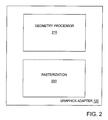
- FIG. 2 is a block diagram of an embodiment of the graphics adapter of FIG. 1;
- FIG. 3 is a block diagram of an embodiment of a geometry pipeline of the graphics adapter of FIG. 2;
- FIG. 4 is a block diagram illustrating functional blocks of a texture coordinate generation stage of the geometry pipeline of FIG. 3;
- FIG. 5 is diagram of a sphere mode calculation circuit of the texture coordinate generation stage of FIG. 4;
- FIG. 6 is a depiction of a scoreboard illustrating resource allocation of the sphere mode calculation circuit of FIG. 5;
- FIG. 7 illustrates the operation of the sphere mode calculation circuit of FIG. 5 .
- FIG. 1 is a block diagram of data processing system 100 according to one embodiment of the present invention.
- system 100 includes one or more processor(s) 102 a through 102 n (generically or collectively referred to herein as processor(s) 102 ) are connected to a system bus 104 .
- processors 102 may be implemented with any of a variety of microprocessor components including, as examples, PowerPC® processors from IBM Corporation, SPARC® processors from Sun Microsystems, and x86 compatible architectures such as the Pentium® family of processors from Intel Corporation and the Athlon® family of processors from Advanced Micro Devices, Inc.
- a system memory (RAM) 106 is accessible to processors 102 via system bus 104 .
- a host bridge 108 is connected between system bus 104 and an IO bus 110 .
- IO bus 110 is typically implemented as a PCI bus (as specified in PCI Local Bus Specification Rev . 2.2 available from the PCI Special Interest Group at www.pcisig.com and incorporated by reference herein), or a PCI derivative such as the Advanced Graphics Protocol (AGP) bus defined by Intel Corporation.
- the depicted embodiment of system 100 includes various peripheral devices including a network adapter 114 suitable for connecting system 100 to computer network and a secondary bridge 120 that provides support for legacy 10 devices such as a keyboard 124 and a mouse 126 .
- System 100 further includes a graphics adapter 120 connected to IO bus 110 .
- the graphics adapter 120 is enabled to process graphics data received via IO bus 110 and typically includes a video controller that controls the image displayed on a display device 121 .
- system memory 106 may include all or portions of an operating system 130 .
- Suitable operating systems include the AIX® operating system from IBM Corporation (or another Unix derivative operating system), a Windows® family operating system from Microsoft, or a network operating system such as JavaOS® from Sun Microsystems.
- An application program 132 generates graphics scenes that are passed to an API 134 .
- API 134 may be the OpenGL® API, the DirectX® API, or another suitable 3D programming interface. API 134 processes graphics scenes generated by application program 132 and, via graphics adapter 120 , maintains the contents of a video display screen, plotter, or other suitable output device.
- graphics adapter 120 includes a geometry processor 210 and a rasterization portion (rasterizer) 220 .
- the geometry processor 210 performs complex calculations in response to data received from API 134 to generate the attributes specified by API 134 .
- Rasterizer 220 determines pixel values for the display device based upon information received from geometry processor 210 and maintains the contents of a frame buffer or other suitable graphics storage facility that is used to stored a representation of the image that is displayed by the display device.
- geometry pipeline 210 receives data generated by API 134 .
- geometry processor 210 includes an interface that receives data, including commands and object coordinates, from IO bus 110 in 32-bit chunks.
- a vertex packer 302 converts the 32-bit chunks into a vertex width internally supported by geometry pipeline 210 .
- the vertex width may vary depending upon the data that is required by the stage.
- vertex packer 302 provides default values (pursuant to the API 134 ) for vertex attributes that are not specified by the application program.
- Vertex packer 302 forwards object coordinates to normal/model view transformation stage 304 where the normal vector is transformed from object space into eye space and the object coordinates are transformed into eye coordinates by translating, scaling, and rotating objects.
- the normalization stage 306 changes a normal vector to a vector of unit length (i.e., a vector having a magnitude of 1.0), while preserving the direction of the original vector.
- normalization stage 306 may generate normalized eye coordinates.
- the texture coordinate generation block 308 as its name implies, is responsible for generating object linear, eye linear, or spherical texture coordinates.
- the lighting stage 310 generates the color of each vertex of an object based on the orientation of the object and its material properties as well as the properties of the scene and any light sources that are defined.
- Texture/projection transformation stage 312 transforms texture coordinates by translating, scaling, and rotating objects and moves objects into a viewing volume by transforming eye coordinates into clip coordinates by translating, rotating, and scaling objects.
- Perspective projection makes objects that are further away from the viewer appear smaller whereas orthogonal projection does not.
- Clipping stage 314 clips objects to a defined viewing volume while fog factor generation stage 316 makes objects fade into the distance by making objects further from the viewer less visible than objects closer to the viewer.
- the perspective division stage 318 transforms clip coordinates to normalized device coordinates [ ⁇ 1,+1] by dividing by the 4th coordinate (the W coordinate).
- the view transformation stage 320 facilitates the rasterization process by transforming normalized device coordinates into screen or window coordinates.
- the vertex funnel 322 converts the internal vertex format into a 32-bit format suitable for an output interface of geometry processor 210 . In addition, vertex funnel 322 may convert one or more floating point values to fixed point values.
- TCG stage 308 includes a TCG Control Unit 400 , a TCG Calculation unit 404 , a TCG Data Path 406 , and TCG sphere coordinate generation circuit (TCG sphere circuit) 402 .
- TCG Control unit 400 exchanges ready/valid signals with a previous stage in the geometry pipeline (normalization stage 306 ) and a subsequent stage in the pipeline (lighting state 310 ) to control the flow of data through the pipeline.
- TCG Control Unit 400 determines the texture mode (such as object linear, eye linear, or spherical) and invokes TCG calculation circuit 404 and TCG sphere circuit 402 as needed for the determined texture mode.
- TCG calculation unit 404 is configured to generate texture coordinates in linear texture modes while TCG sphere circuit 402 is enabled to generate sphere mode texture coordinates in response to receiving a unit vector, a normal vector, and an appropriate initiation signal from TCG Control Unit 400 .
- the TCG Data Path 406 buffers information from TCG calculation unit 404 , TCG control Unit 400 , and TCG sphere circuit 402 for retrieval by the subsequent geometry pipeline stages.
- TCG Data Path 406 performs multiplexing to select data from TCG sphere circuit 402 or TCG calculation 404 for forwarding to subsequent stages of the pipeline depending upon the texture coordinate mode. In an eye or linear mode, TCG Data Path 406 may select data from TCG calculation circuit 404 for forwarding while, in a spherical texture coordinate mode, TCG Data Path 406 may select data from TCG Sphere Circuit 402 .
- the TCG sphere circuit 402 includes a set of input multiplexers 502 a (the MA multiplexer), 502 b (MB multiplexer), 502 c (AA multiplexer), 502 d (AB multiplexer), 502 e (L1 multiplexer), 502 f (L2 multiplexer), and 502 g (L3 multiplexer) (all generically or collectively referred to herein as multiplexer(s) 502 ), a set of latches 504 a (the MA latch), 504 b (MB latch), 504 c (AA latch), 504 d (AB latch), 504 e (L1 latch), 504 f (L2 latch), and 504 g (L3 latch) (generically or collectively referred to herein as latch(es) 504 ) where each latch 504 is connected to the output of a corresponding input multiplexer 502 .
- the MA multiplexer the MA multiplexer
- 502 b MB multiplexer
- TCG sphere circuit 402 as depicted in FIG. 5 further includes a set of functional units including a floating point multiplier 506 , a floating point adder 508 , an inverse square root unit 512 , and a floating point compare-to-zero unit 514 .
- TCG sphere circuit 402 includes, an S output 25 multiplexer 516 , a T output multiplexer 518 , and a controller 510 that maintains the state of the multiplexer select input signals in each cycle.
- the outputs of latches 504 a and 504 b are connected to the inputs of floating point multiplier 506 while the outputs of latches 504 c and 504 d are connected to the inputs of floating point adder 508 .
- the latches 504 e , 504 f , and 504 g are used to hold intermediate results in the calculation of the sphere mode texture coordinates. Thus these outputs are shown in FIG. 5 as being fed back to the inputs of the set of multiplexers 502 .
- the controller receives a sphere start signal 408 from the TCG control unit 400 (FIG. 4) that initiates the calculation of the sphere mode texture coordinates.
- TCG stage 308 Upon receiving a VALID signal from the prior stage of geometry pipeline 210 (i.e., the normalization stage 306 ) and sending a READY signal to normalization stage 306 , TCG stage 308 receives a unit vector (u) and a normal vector (n) and the TCG Control unit 400 determines whether the sphere mode is active. If the sphere mode is active, TCG control unit asserts the sphere start signal 408 that informs controller 510 of TCG Sphere circuit 402 that sphere mode texture coordinates are to be generated.
- the sphere mode texture coordinates are generated in compliance with the OpenGL® specification.
- OpenGL® defines the sphere mode texture coordinates S and T as:
- T r y /m +0.5 if m ⁇ 0.
- TCG control unit 400 asserts sphere start signal 408 only after TCG sphere circuit 402 has received a valid u vector and a valid n vector.
- controller 510 Upon detecting the assertion of sphere start signal 408 , controller 510 begins controlling the selector signals to the various input multiplexers 502 .
- the inputs that are available to each of the input multiplexers 502 are indicated in FIG.
- multiplexer 502 a may select from 8 floating point inputs, three of which comprise the x, y, and z components of the normal vector n. In addition, multiplexer 502 a may select from the A, R, L1, L3 and 0.5 signals.
- Multiplexer 502 b may select from 6 inputs, three of which are the x, y, and z components of the unit vector u and the remaining three of which are the A, L1, and L2 signals.
- the available inputs for the remaining multiplexers 502 c , 502 d , 502 e , 502 f , and 502 g are as depicted in FIG. 5 .
- the controller 510 cycles through a defined set of steps in the process of calculating the S and T values by appropriately controlling the select inputs to the set of input multiplexers 502 a through 502 g , the S out multiplexer 516 , and the T out multiplexer 518 during each cycle of the process. At the end of the process the S and T values are valid on S signal 416 and T signal 418 respectively.
- the output of the floating point compare-to-zero circuit 514 is routed to the controller 510 to account for the case in which the m value, as defined above, is zero.
- the sphere controller selects the 0.5 inputs for the S out multiplexer 516 and the T out multiplexer 518 in compliance with the OpenGL® specification.
- Scoreboard 600 identifies the inputs that controller 510 selects during the corresponding clock cycle and indicates (in the column labeled “Next Ss”) the next cycle that controller 510 will execute. Initially, controller 510 idles in cycle 0 (the cycle numbers are as indicated in the column identified as (“Curr Ss”) until the sphere start input is asserted (as indicated by the “T” in the column labeled (“start”), at which point controller 510 increments to cycle 1 (as indicated in the Next Ss column).
- controller 510 selects the x n input of MA multiplexer 502 a , the x e input of MB multiplexer 502 b , the x n input of AA multiplexer 502 c , the x n input of AB multiplexer 502 d , the L1 input of L1 multiplexer 502 e , and the L2 input of L2 multiplexer 502 f (the select input of L3 multiplexer 502 g is a “don't care” in cycle 0).
- state transition diagram 700 it is seen that the select inputs identified in cycle 0 of scoreboard 600 route the x n and x c inputs to the A and B inputs of floating point multiplier 506 and the x n and x n inputs to the A and B inputs of floating point adder 508 (after appropriate clocking through the corresponding latches 504 ).
- floating point multiplier 506 and floating point adder 508 each require 2 cycles to complete the corresponding floating point operation.
- the output of floating point multiplier 506 will indicate the floating point product of x n and x e two cycles after the input values are presented to multiplier 506 (i.e., in cycle 3) and the output of floating point adder 508 will indicate the floating point sum of x n and x n (i.e., 2x n ).
- controller 510 selects the M input of L1 multiplexer 502 e and the A input of L2 multiplexer 502 f thereby latching the floating point product x n *x e into L1 latch 504 e and the floating point sum 2x n into L2 latch 504 f , where they can be used for subsequent operations.
- FIGS. 6 and 7 indicate the state of each of the latches 504 and each of the multiplexers 502 , 516 , and 518 .
- TCG sphere circuit 402 begins the process of calculating S and T values by first calculating the dot product of the n and u vectors using floating point multiplier 506 , floating point adder 508 , and appropriate values for the select inputs to multiplexers 502 a , 502 b , 502 c , 502 d , and 502 e in cycles 0 through 7 thereby producing the dot product in cycle 9 and latching it into L2 latch 504 f in cycle 10 .
- circuit 402 calculates the values 2x n , 2y n , and 2z n using adder 508 and stores the values in latches 504 e , 504 f , and 504 g respectively for subsequent use in calculating r x , r y , and r z +1 (as defined above) in cycles 13, 14, and 15 respectively. It should be noted that, because the depicted implementation of circuit 402 includes just a single floating point multiplier 506 and a single floating point adder 508 , there can be, at most, just one occurrence of the multiplier and the adder in each cycle of FIG. 7 .
- the values r x and r y are stored in L1 latch 504 e and L2 latch 504 f respectively in cycles 16 and 17 for subsequent use in calculating S and T values. Simultaneously, the r x , r y , and r z +1 quantities are squared (multiplied by themselves) using floating point multiplier 506 in cycles 16, 17, and 18 to produce the quantities r x 2 , r y 2 , and (r z +1) 2 , which are needed to determine the value m.
- the r x and r y values produced in cycles 18 and 14 respectively are latched into L1 latch 504 e and L2 latch 504 f in cycles 16 and 17 and multiplied by 0.5 using multiplier 506 in cycles 20 and 21 to generated the values 0.5r x and 0.5r y , which are latched in L1 latch 504 e and L2 latch 504 f in cycles 23 and 24.
- the inverse square root unit 512 calculates the quantity (rr) ⁇ 0.5 from rr, which is valid at the input of inverse square root unit 512 in cycle 26.
- the inverse square root unit requires five cycles (cycles 26-30) to generate the output value (rr) ⁇ 0.5 , which is latched into L3 latch 504 g in cycle 32.
- the value (rr) ⁇ 0.5 is then multiplied by the values 0.5r x and 0.5r y using multiplier 506 in cycles 32 and 33 and added to 0.5 using adder 508 in cycles 35 and 36 to produce the values 0.5r x /(rr) 0.5 +0.5 and 0.5r y /(rr) 0.5 +0.5, which are latched into L1 latch 504 e and L2 latch 504 f in cycles 38 and 39 respectively.
- the 0.5 inputs to S Out multiplexer 516 and T Out multiplexer 518 are selected as the S and T values that are output from TCG Sphere circuit 402 . If, rr is not equal to 0, the L1 and L2 inputs to multiplexers 516 and 518 are selected as the S and T values. Referring back to FIG. 6, it is seen in cycles 38 and 39 that, upon generating the S and T values, controller 510 asserts the sphere done signal 410 that informs TCG Control unit 400 that the calculation is complete.
- TCG Sphere circuit 402 calculates a pair of floating point values representing the S and T values as specified in the OpenGL® specification in less than 40 machine cycles. It will be appreciated that, while the S and T values may be computed in software, the number of cycles required to do so would be significantly greater than 40.
- the hardware implementation described herein is a concise design that achieves a significant performance benefit with a compact circuit that uses just a single floating point adder, a single floating point multiplier, an inverse square unit, a floating point compare to zero unit, a state machine (controller 510 ) and conventional multiplexer and latch logic.
- TCG Sphere circuit 402 While additional resources (such as an additional floating point adder or multiplier) may be added to other embodiments of TCG sphere circuit 402 , the incremental increase in performance achieved by doing so is not cost justified (in terms of the increase in area required to implement TCG Sphere circuit 402 ) in most graphic applications. In other words, the disclosed implementation of TCG Sphere circuit 402 embodies an optimized tradeoff between performance and cost.
- additional resources such as an additional floating point adder or multiplier
Abstract
Description
Claims (19)
Priority Applications (1)
| Application Number | Priority Date | Filing Date | Title |
|---|---|---|---|
| US09/616,143 US6822656B1 (en) | 2000-07-13 | 2000-07-13 | Sphere mode texture coordinate generator |
Applications Claiming Priority (1)
| Application Number | Priority Date | Filing Date | Title |
|---|---|---|---|
| US09/616,143 US6822656B1 (en) | 2000-07-13 | 2000-07-13 | Sphere mode texture coordinate generator |
Publications (1)
| Publication Number | Publication Date |
|---|---|
| US6822656B1 true US6822656B1 (en) | 2004-11-23 |
Family
ID=33435485
Family Applications (1)
| Application Number | Title | Priority Date | Filing Date |
|---|---|---|---|
| US09/616,143 Expired - Lifetime US6822656B1 (en) | 2000-07-13 | 2000-07-13 | Sphere mode texture coordinate generator |
Country Status (1)
| Country | Link |
|---|---|
| US (1) | US6822656B1 (en) |
Cited By (2)
| Publication number | Priority date | Publication date | Assignee | Title |
|---|---|---|---|---|
| US20110199286A1 (en) * | 2010-02-13 | 2011-08-18 | Robin Dziama | Spherical Electronic LCD Display |
| US8610737B2 (en) * | 2010-05-27 | 2013-12-17 | National Taiwan University | Graphic processing unit (GPU) with configurable filtering module and operation method thereof |
Citations (5)
| Publication number | Priority date | Publication date | Assignee | Title |
|---|---|---|---|---|
| US5517611A (en) * | 1993-06-04 | 1996-05-14 | Sun Microsystems, Inc. | Floating-point processor for a high performance three dimensional graphics accelerator |
| US5561756A (en) * | 1992-05-08 | 1996-10-01 | Apple Computer, Inc. | Textured sphere and spherical environment map rendering using texture map double indirection |
| US5870509A (en) * | 1995-12-12 | 1999-02-09 | Hewlett-Packard Company | Texture coordinate alignment system and method |
| US5930519A (en) * | 1997-04-30 | 1999-07-27 | Hewlett Packard Company | Distributed branch logic system and method for a geometry accelerator |
| US5969726A (en) * | 1997-05-30 | 1999-10-19 | Hewlett-Packard Co. | Caching and coherency control of multiple geometry accelerators in a computer graphics system |
-
2000
- 2000-07-13 US US09/616,143 patent/US6822656B1/en not_active Expired - Lifetime
Patent Citations (5)
| Publication number | Priority date | Publication date | Assignee | Title |
|---|---|---|---|---|
| US5561756A (en) * | 1992-05-08 | 1996-10-01 | Apple Computer, Inc. | Textured sphere and spherical environment map rendering using texture map double indirection |
| US5517611A (en) * | 1993-06-04 | 1996-05-14 | Sun Microsystems, Inc. | Floating-point processor for a high performance three dimensional graphics accelerator |
| US5870509A (en) * | 1995-12-12 | 1999-02-09 | Hewlett-Packard Company | Texture coordinate alignment system and method |
| US5930519A (en) * | 1997-04-30 | 1999-07-27 | Hewlett Packard Company | Distributed branch logic system and method for a geometry accelerator |
| US5969726A (en) * | 1997-05-30 | 1999-10-19 | Hewlett-Packard Co. | Caching and coherency control of multiple geometry accelerators in a computer graphics system |
Cited By (2)
| Publication number | Priority date | Publication date | Assignee | Title |
|---|---|---|---|---|
| US20110199286A1 (en) * | 2010-02-13 | 2011-08-18 | Robin Dziama | Spherical Electronic LCD Display |
| US8610737B2 (en) * | 2010-05-27 | 2013-12-17 | National Taiwan University | Graphic processing unit (GPU) with configurable filtering module and operation method thereof |
Similar Documents
| Publication | Publication Date | Title |
|---|---|---|
| US6417858B1 (en) | Processor for geometry transformations and lighting calculations | |
| US7292242B1 (en) | Clipping with addition of vertices to existing primitives | |
| US5274760A (en) | Extendable multiple image-buffer for graphics systems | |
| KR100278565B1 (en) | Geometry pipeline implemented on a simd machine | |
| Wylie et al. | Tetrahedral projection using vertex shaders | |
| JP5563054B2 (en) | Fragment shader bypass in graphics processing unit, apparatus and method thereof | |
| US8098257B2 (en) | Filtering unit for floating-point texture data | |
| JP3860859B2 (en) | Computer graphics system with high performance primitive clipping preprocessing | |
| US6166743A (en) | Method and system for improved z-test during image rendering | |
| US9024969B2 (en) | Method and device for performing user-defined clipping in object space | |
| JP2010507875A (en) | 3D clipping in graphics processing unit | |
| JPH0727571B2 (en) | Raster scan display device and graphic data transfer method | |
| US8907979B2 (en) | Fast rendering of knockout groups using a depth buffer of a graphics processing unit | |
| US7466322B1 (en) | Clipping graphics primitives to the w=0 plane | |
| US6480200B1 (en) | Method and apparatus for deferred texture validation on a multi-tasking computer | |
| US7310103B2 (en) | Pipelined 2D viewport clip circuit | |
| KR20020001518A (en) | A method and apparatus in a data processing system for full scene anti-aliasing | |
| US6681237B1 (en) | Exponentiation circuit for graphics adapter | |
| US20030160799A1 (en) | Reconfigurable hardware filter for texture mapping and image processing | |
| US6606097B1 (en) | Circuit for generating frame buffer values | |
| US20020126127A1 (en) | Lighting processing circuitry for graphics adapter | |
| US6850244B2 (en) | Apparatus and method for gradient mapping in a graphics processing system | |
| US6822656B1 (en) | Sphere mode texture coordinate generator | |
| US6731303B1 (en) | Hardware perspective correction of pixel coordinates and texture coordinates | |
| US6885375B2 (en) | Stalling pipelines in large designs |
Legal Events
| Date | Code | Title | Description |
|---|---|---|---|
| AS | Assignment |
Owner name: INTERNATIONAL BUSINESS MACHINES CORPORATION, NEW Y Free format text: ASSIGNMENT OF ASSIGNORS INTEREST;ASSIGNORS:ST. CLAIR, JOE C.;VAN NOSTRAND, MARK E.;REEL/FRAME:010995/0086 Effective date: 20000711 |
|
| FEPP | Fee payment procedure |
Free format text: PAYOR NUMBER ASSIGNED (ORIGINAL EVENT CODE: ASPN); ENTITY STATUS OF PATENT OWNER: LARGE ENTITY |
|
| STCF | Information on status: patent grant |
Free format text: PATENTED CASE |
|
| CC | Certificate of correction | ||
| AS | Assignment |
Owner name: NVIDIA CORPORATION, CALIFORNIA Free format text: ASSIGNMENT OF ASSIGNORS INTEREST;ASSIGNOR:INTERNATIONAL BUSINESS MACHINES CORPORATION;REEL/FRAME:017982/0436 Effective date: 20060630 |
|
| FPAY | Fee payment |
Year of fee payment: 4 |
|
| FPAY | Fee payment |
Year of fee payment: 8 |
|
| FPAY | Fee payment |
Year of fee payment: 12 |