US6801034B2 - Method and apparatus of acquiring large FOV images without slab-boundary artifacts - Google Patents
Method and apparatus of acquiring large FOV images without slab-boundary artifacts Download PDFInfo
- Publication number
- US6801034B2 US6801034B2 US09/681,420 US68142001A US6801034B2 US 6801034 B2 US6801034 B2 US 6801034B2 US 68142001 A US68142001 A US 68142001A US 6801034 B2 US6801034 B2 US 6801034B2
- Authority
- US
- United States
- Prior art keywords
- data
- slab
- space
- image
- acquired
- Prior art date
- Legal status (The legal status is an assumption and is not a legal conclusion. Google has not performed a legal analysis and makes no representation as to the accuracy of the status listed.)
- Expired - Lifetime, expires
Links
- 238000000034 method Methods 0.000 title claims abstract description 38
- 230000033001 locomotion Effects 0.000 claims abstract description 87
- 238000003384 imaging method Methods 0.000 claims description 42
- 238000002595 magnetic resonance imaging Methods 0.000 claims description 27
- 238000004590 computer program Methods 0.000 claims description 15
- 230000005284 excitation Effects 0.000 claims description 10
- 238000005070 sampling Methods 0.000 claims description 8
- 239000011159 matrix material Substances 0.000 claims description 7
- 230000001131 transforming effect Effects 0.000 claims description 7
- 230000000717 retained effect Effects 0.000 claims description 6
- 230000007704 transition Effects 0.000 claims description 3
- 125000004122 cyclic group Chemical group 0.000 claims description 2
- 230000001419 dependent effect Effects 0.000 claims 2
- 210000003484 anatomy Anatomy 0.000 claims 1
- 238000001914 filtration Methods 0.000 claims 1
- 238000002059 diagnostic imaging Methods 0.000 description 4
- 238000010586 diagram Methods 0.000 description 3
- 238000012545 processing Methods 0.000 description 3
- 230000009466 transformation Effects 0.000 description 3
- 238000003491 array Methods 0.000 description 2
- 230000007423 decrease Effects 0.000 description 2
- 230000003247 decreasing effect Effects 0.000 description 2
- 230000007774 longterm Effects 0.000 description 2
- 230000004048 modification Effects 0.000 description 2
- 238000012986 modification Methods 0.000 description 2
- 230000008569 process Effects 0.000 description 2
- 239000000126 substance Substances 0.000 description 2
- 238000004458 analytical method Methods 0.000 description 1
- 238000013459 approach Methods 0.000 description 1
- 230000000694 effects Effects 0.000 description 1
- 230000002452 interceptive effect Effects 0.000 description 1
- 230000004807 localization Effects 0.000 description 1
- 230000005415 magnetization Effects 0.000 description 1
- 238000004519 manufacturing process Methods 0.000 description 1
- 238000005259 measurement Methods 0.000 description 1
- 230000004044 response Effects 0.000 description 1
- 230000035945 sensitivity Effects 0.000 description 1
Images


Classifications
-
- G—PHYSICS
- G01—MEASURING; TESTING
- G01R—MEASURING ELECTRIC VARIABLES; MEASURING MAGNETIC VARIABLES
- G01R33/00—Arrangements or instruments for measuring magnetic variables
- G01R33/20—Arrangements or instruments for measuring magnetic variables involving magnetic resonance
- G01R33/28—Details of apparatus provided for in groups G01R33/44 - G01R33/64
-
- G—PHYSICS
- G01—MEASURING; TESTING
- G01R—MEASURING ELECTRIC VARIABLES; MEASURING MAGNETIC VARIABLES
- G01R33/00—Arrangements or instruments for measuring magnetic variables
- G01R33/20—Arrangements or instruments for measuring magnetic variables involving magnetic resonance
- G01R33/44—Arrangements or instruments for measuring magnetic variables involving magnetic resonance using nuclear magnetic resonance [NMR]
- G01R33/48—NMR imaging systems
- G01R33/54—Signal processing systems, e.g. using pulse sequences ; Generation or control of pulse sequences; Operator console
- G01R33/56—Image enhancement or correction, e.g. subtraction or averaging techniques, e.g. improvement of signal-to-noise ratio and resolution
- G01R33/563—Image enhancement or correction, e.g. subtraction or averaging techniques, e.g. improvement of signal-to-noise ratio and resolution of moving material, e.g. flow contrast angiography
- G01R33/56375—Intentional motion of the sample during MR, e.g. moving table imaging
-
- G—PHYSICS
- G01—MEASURING; TESTING
- G01R—MEASURING ELECTRIC VARIABLES; MEASURING MAGNETIC VARIABLES
- G01R33/00—Arrangements or instruments for measuring magnetic variables
- G01R33/20—Arrangements or instruments for measuring magnetic variables involving magnetic resonance
- G01R33/44—Arrangements or instruments for measuring magnetic variables involving magnetic resonance using nuclear magnetic resonance [NMR]
- G01R33/48—NMR imaging systems
- G01R33/54—Signal processing systems, e.g. using pulse sequences ; Generation or control of pulse sequences; Operator console
Definitions
- the present invention relates generally to an improved method of medical imaging over large areas, and more particularly, to a method and apparatus of acquiring magnetic resonance (MR) images over an area that is greater than the optimal imaging area of an MR scanner using step-wise movement of a table through the MR scanner without incurring slab-boundary artifacts.
- MR magnetic resonance
- polarizing field B 0 When a substance such as human tissue is subjected to a uniform magnetic field (polarizing field B 0 ), the individual magnetic moments of the spins in the tissue attempt to align with this polarizing field, but precess about it in random order at their characteristic Larmor frequency. If the substance, or tissue, is subjected to a magnetic field (excitation field B 1 ) which is in the x-y plane and which is near the Larmor frequency, the net aligned moment, or “longitudinal magnetization”, M Z , may be rotated, or “tipped”, into the x-y plane to produce a net transverse magnetic moment M t . A signal is emitted by the excited spins after the excitation signal B 1 is terminated and this signal may be received and processed to form an image.
- excitation field B 1 which is in the x-y plane and which is near the Larmor frequency
- magnetic field gradients G x G y and G z
- the region to be imaged is scanned by a sequence of measurement cycles in which these gradients vary according to the particular localization method being used.
- the resulting set of received MR signals are digitized and processed to reconstruct the image using one of many well known reconstruction techniques.
- the volume for acquiring MR data with optimal gradient linearity, having a uniform magnetic field B 0 , and uniform radio frequency (RF) homogeneity is of limited extent. Desired fields-of-view (FOV) that exceed this limited volume are traditionally acquired in sections, with table motion between scans. The resulting concatenated images often exhibit discontinuities at the slab junctions. These slab-boundary artifacts result in non-ideal images. When these artifacts are either severe or occur in a critical region-of-interest, complete re-acquisition of data may be needed for a thorough analysis.
- FOV radio frequency
- the present invention relates to a system and method of acquiring large FOV MR images using incremental table motion for increased volume coverage that results in reconstructed images without discontinuities.
- Slab-boundary artifacts are eliminated in a 3D acquisition sequence by stepping an imaging object with respect to the optimal volume of the imaging apparatus, or vice versa. For example, stepping a moveable table in small increments and using a unique acquisition and reconstruction scheme.
- the thickness of the slab which is smaller than the desired FOV, is selected to remain within the optimal volume of the MR system.
- the selected slab position remains fixed relative to the magnet of the MR scanner during the scan, and the table is moved in incremental steps during scanning of the entire FOV.
- MR data is acquired by applying an excitation that excites spins and applying magnetic field gradient waveforms to encode the volume of interest.
- the volume of interest is restricted in the direction of table motion.
- the magnetic field gradients traverse k-space following a trajectory that is uniform in the k-space dimension that is in the direction of table motion.
- the magnetic field gradient waveforms that encode the k-space directions perpendicular to table motion are divided into subsets.
- all the k-space data in the direction of table motion are acquired for a subset of the remaining two k-space dimensions.
- data is transformed in the direction of table motion, sorted, and aligned to match anatomical locations in the direction of table motion. This procedure is repeated to fill the entire 3D matrix.
- a final image is reconstructed by transforming the data in the dimensions perpendicular to table motion.
- This stepped table approach provides reconstructed images absent of slab-boundary artifacts over large FOV imaging areas.
- a method of imaging large volumes without resulting slab-boundary artifacts includes defining a desired FOV larger than an optimal imaging volume of an MR scanner and selecting a slab thickness in a first direction that is smaller than the desired FOV but that is within the optimal imaging volume of the MR scanner.
- MR data is then acquired by exciting and encoding spins to acquire data that is restricted to the selected slab thickness.
- the imaging area is then moved step-wise with respect to the imaging object using a step distance that is preferably a multiple of the image resolution in the direction of table motion. This process is repeated until the desired FOV is fully encoded using a series of cyclically repeated magnetic field gradient waveforms. Scan time can be minimized by applying time-varying magnetic field gradient waveforms during signal acquisition.
- the selected trajectory need only be uniform in the direction of motion. Artifacts are reduced by using stepped acquisitions as opposed to continuous motion acquisitions.
- an MRI apparatus to acquire multiple sets of MR data with a moving table and reconstruct MR images without slab-boundary artifacts that includes a magnetic resonance imaging system having an RF transceiver system and a plurality of gradient coils positioned about a bore of a magnet to impress a polarizing magnetic field.
- An RF switch is controlled by a pulse module to transmit and receive RF signals to and from an RF coil assembly to acquire MR data.
- a patient table is moveable fore and aft in the MR system about the magnetic bore to translate the patient so that an FOV larger than the optimal scanning area of the MRI system can be scanned.
- a computer is programmed to receive input defining a desired FOV larger than the optimal imaging volume of the MR system.
- the computer is also capable of defining a fixed slab with respect to the magnet to acquire the MR data therein.
- the computer acquires full MR data in the direction of table motion for a subset of the data in the directions perpendicular to table motion, and then increments position of the patient table while maintaining the position of the fixed slab.
- the algorithm is repeated, collecting the necessary MR data across the defined FOV.
- the MR data is first transformed in the direction of table motion, and then aligned to match anatomic locations across slab boundaries. Thereafter, the MR data is transformed with respect to the remaining two dimensions to reconstruct an MR image.
- Yet another aspect of the invention includes a computer program having a set of instructions executed by a computer to control a medical imaging scanner and create images across scanning boundaries without significant boundary artifacts.
- the computer is caused to select an FOV spanning an area greater than a predefined optimal image area of the medical imaging scanner, apply an RF pulse to excite a region of interest, and apply magnetic field gradients to encode the region of interest in a first direction.
- the volume of interest is limited in the direction of table motion either by using a slab-selective RF pulse or by acquiring the data in such a way that an acquisition filter can be used to restrict the spatial extent.
- Three-dimensional image data can then be acquired in the first direction as a subset of a second and third direction for each table movement.
- the computer then causes a patient table to move an incremental step with respect to the medical imaging scanner, and repeat the image data acquisition in the first direction for he remaining two directions until sufficient data is acquired across the entire FOV.
- An image can be reconstructed without slab-boundary artifacts after aligning anatomical data in the first direction.
- FIG. 1 is a schematic block diagram of an MR imaging system for use with the present invention.
- FIG. 2 is a diagram illustrating one embodiment of a data acquisition technique in accordance with the present invention.
- FIG. 3 is a diagram similar to FIG. 2, illustrating another embodiment for data acquisition in accordance with the present invention.
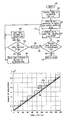
- FIG. 4 is a flow chart demonstrating a data acquisition algorithm for use with that shown in FIGS. 2 and 3.
- FIG. 5 is a flow chart showing the data processing steps employed either during or after the data acquisition of FIG. 4 .
- FIG. 6 is a plot of a number of acquisitions versus total z-FOV for four values of slab thickness.
- FIG. 7 is a plot of total scan time versus total z-FOV for the four values of slab thickness plotted in FIG. 6 .
- FIG. 1 the major components of a preferred magnetic rcsonancc imaging (MRT) system 10 incorporating the present invention are shown.
- the operation of the system is controlled from an operator console 12 which includes a keyboard or other input device 13 , a control panel 14 , and a display 16 .
- the console 12 communicates through a link 18 with a separate computer system 20 that enables an operator to control the production and display of images on the display 16 .
- the computer system 20 includes a number of modules which communicate with each other. through a backplane 20 a . These include an image processor module 22 , a CPU module 24 and a memory module 26 , known in the art as a frame buffer for storing image data arrays.
- the computer system 20 is linked to disk storage 28 and tape drive 30 for storage of image data and programs, and communicates with a separate system control 32 through a high speed serial link 34 .
- the input device 13 can include a mouse, joystick, keyboard, track ball, touch activated screen, light wand, voice control, or any similar or equivalent input device, and may be used for interactive geometry prescription.
- the system control 32 includes a set of modules connected together by a backplane 32 a . These include a CPU module 36 and a pulse generator module 38 which connects to the operator console 12 through a serial link 40 . It is through link 40 that the system control 32 receives commands from the operator to indicate the scan sequence that is to be performed.
- the pulse generator module 38 operates the system components to carry out the desired scan sequence and produces data which indicates the timing, strength and shape of the RF pulses produced, and the timing and length of the data acquisition window.
- the pulse generator module 38 connects to a set of gradient amplifiers 42 , to indicate the timing and shape of the gradient pulses that are produced during the scan.
- the pulse generator module 38 can also receive patient data from a physiological acquisition controller 44 that receives signals from a number of different sensors connected to the patient, such as ECG signals from electrodes attached to the patient. And finally, the pulse generator module 38 connects to a scan room interface circuit 46 which receives signals from various sensors associated with the condition of the patient and the magnet system. It is also through the scan room interface circuit 46 that a patient positioning system 48 receives commands to move the patient to the desired position for the scan.
- the gradient waveforms produced by the pulse generator module 38 are applied to the gradient amplifier system 42 having G x , G y , and G z amplifiers.
- Each gradient amplifier excites a corresponding physical gradient coil in a gradient coil assembly generally designated 50 to produce the magnetic field gradients used for spatially encoding acquired signals.
- the gradient coil assembly 50 forms part of a magnet assembly 52 which includes a polarizing magnet 54 and a whole-body RF coil 56 .
- a transceiver module 58 in the system control 32 produces pulses which are amplified by an RF amplifier 60 and coupled to the RF coil 56 by a transmit/receive switch 62 .
- the resulting signals emitted by the excited nuclei in the patient may be sensed by the same RF coil 56 and coupled through the transmit/receive switch 62 to a preamplifier 64 .
- the amplified MR signals are demodulated, filtered, and digitized in the receiver section of the transceiver 58 .
- the transmit/receive switch 62 is controlled by a signal from the pulse generator module 38 to electrically connect the RF amplifier 60 to the coil 56 during the transmit mode and to connect the preamplifier 64 to the coil 56 during the receive mode.
- the transmit/receive switch 62 can also enable a separate RF coil (for example, a surface coil) to be used in either the transmit or receive mode.
- the MR signals picked up by the RF coil 56 are digitized by the transceiver module 58 and transferred to a memory module 66 in the system control 32 .
- a scan is complete when an array of raw k-space data has been acquired in the memory module 66 .
- This raw k-space data is processed as necessary and rearranged into separate k-space data arrays for each image to be reconstructed, and each of these is input to an array processor 68 which operates to Fourier transform the data into an array of image data.
- This image data is conveyed through the serial link 34 to the computer system 20 where it is stored in memory, such as disk storage 28 .
- this image data may be archived in long term storage, such as on the tape drive 30 or any mass storage device, or it may be further processed by the image processor 22 and conveyed to the operator console 12 and presented on the display 16 .
- the present invention includes a method and system suitable for use with the above-referenced MRI system, or any similar or equivalent system for obtaining MR images.
- MRI system or any similar or equivalent system for obtaining MR images.
- data acquired in sections to form large FOV 3D images can be acquired without significant slab-boundary artifacts.
- MR data is acquired by repeatedly applying an excitation that excites spins and applying magnetic field gradient waveforms to encode the volume of interest.
- a z slab selective RF pulse is used to excite the volume of interest in the z-direction and a 3D k-space trajectory encodes the volume selected.
- 3D k-space trajectories include a 3D EPI k-space trajectory, a cylindrical-stack of EPI k-space trajectory, a stack-of-spirals k-space trajectory, a stack-of-TWIRL k-space trajectory, a stack-of-projection-reconstruction k-space trajectory, and a 3DFT k-space trajectory.
- the spatial extent of the acquired data is restricted in the direction of motion using a method such as using a slab-selective RF pulse or by using an acquisition strategy that allows the acquisition filter to restrict the volume of interest. Therefore, in the examples shown and in a preferred embodiment, the direction of table motion is in the z-direction.
- the x-y-z orientation is arbitrary and the invention is not so limited.
- the table moves relative to the system. However, as one skilled in the art will readily recognize it is equivalent to have the system move relative to the subject and the invention is not so limited.
- the table is moved to cover the desired FOV while the slab position remains fixed relative to the magnet in the MRI system.
- full k-space data in the direction of table motion is acquired for a subset of the data in the other two dimensions by using one or a series of magnetic field gradient waveforms.
- full k z data is acquired for a subset of k x ⁇ k y by using a series of magnetic field gradient waveforms.
- no data is acquired during table motion, but RF excitations and magnetic field gradient waveforms are continued to preserve a steady-state condition.
- FIG. 2 illustrates one embodiment of the present invention for acquiring data.
- the table is step-wise incremented 15 times with data acquisitions 106 in 16 table positions along the desired FOV.
- Each of the table increments are of equal distance ⁇ z .
- a patient 100 is positioned on a moveable table 102 , which moves fore and aft 104 within the MRT scanner 10 with respect to the magnet and the optimal imaging area 108 of the MRI scanner.
- the desired FOV 110 is substantially larger than the optimal imaging area 108 , which is generally. larger than a selected slab thickness 112 .
- the table motion in this simplified example is in the z direction.
- N 2 and the retained slab thickness may be reduced slightly after acquisition if edge slices are dropped from each 2 -k z -k y data set to minimize the effect of imperfections in the slab profile.
- the optimal imaging area 108 is defined by the physical characteristics of the MRI system 10 . It is preferred to define a volume of interest, or slab, 114 to be within the optimal imaging area 108 .
- each of the table increments throughout the desired FOV 110 arc of equal distance. Accordingly, any of the aforementioned parameters con be adjusted as desired. That is, the slab thickness, 112 may be made larger or smaller, or the number of table positions and data acquisition sets 106 can be increased or decreased, above or below the 16 that are shown.
- the minimum number of table positions desired to reconstruct an image is equal to the number of waveform subsets, N wf .
- the number of z-pixels, N z retained in each excited slab, as well as the number of k x -k y subsets can be modified as desired. Preferably however, N z is kept greater than or equal to N wf . One such modification will be described with reference to FIG. 3 .
- each table position 1 - 16 includes complete sampling in the direction of table motion which in this case is the z-direction, for a subset of the k x -k y data, or more generally, in the directions perpendicular to the direction of table motion. Accordingly, either after all the data at each table position is acquired, or after all the data is acquired for a complete image, the data is Fourier transformed in the direction of table motion, in this case in the z direction, FFT(z), to form an array of z-k x -k y data 120 .
- the patient table 102 is moved in steps until the entire FOV 110 is covered.
- full z-encoding data, or encoding data in the direction of table motion is acquired for a subset of the k x -k y data, which are the two directions perpendicular to the table motion. While no data is acquired while the table is moving, it is desirable to continue the RF excitations and magnetic field gradient waveforms to preserve the steady-state condition. Further, it is desirable that over-sampling of MR data in a first direction, such as z-direction, is avoided.
- data acquired at different table positions are then sorted and aligned to match anatomic z locations, thereby filling the z-k x -k y space.
- the table step distances are multiples of the z-resolution and are selected to ensure complete sampling of the z-k x k y matrix.
- data at the slab edges can be dropped as required by imperfections in the slab-select profile.
- a final reconstructed image 130 is formed by gridding, if necessary, and Fourier transforming the fully sampled data array 120 with respect to x and y.
- N z the number of z-pixels retained, N z , must be at least equal to the number of k x -k y waveform subsets, N wf .
- FIG. 3 which also illustrates a simple example assuming table motion in the z direction
- increasing the slab thickness 132 while maintaining the z resolution results in an increase in the number of z-pixels, N that are encoded at each table position.
- the distance between table positions 1 , 2 , 3 , and 4 is less than that between table positions 4 and table position 5 . Therefore, using a thicker slab, fewer movements of the table are required for the same spatial coverage. This results in an overall faster acquisition for the same size FOV, as compared to that in FIG. 2, if the time to initiate table motion is long relative to the time for a single acquisition. Even though increasing the slab thickness, N z , incrementally increases individual acquisition time for each slab, the total scan time decreases because the time to initiate table motion dominates. Thus, in the case when the time to initiate table motion is long relative to the time for a single acquisition, scan time is minimized by minimizing the number of table movements. With current equipment, it typically takes approximately one second to initiate table motion. While reducing this time is the long-term desired solution, it is not practical in the short term since it requires significant changes to the system architecture.
- the data is Fourier transformed with respect to z to obtain a z-k x -k y data set 136 .
- the data acquired at different table positions can then be sorted and aligned to match anatomic z locations.
- a final image 138 is reconstructed by again first gridding, if necessary, and then Fourier transforming the fully sampled data with respect to x and y, FFT (xy).
- the table step distances are multiples of the pixel size in the direction of table motion and are selected to ensure complete sampling of the 3D matrix.
- the number of table steps required depends on the relative number of pixels retained in the excited slab, N z , for the case of motion in the z direction, and the number of magnetic field gradient waveform subsets required to fully encode the dimensions perpendicular to table motion, N wf .
- N z should be at least equal to N wf . However, if N z is greater than N wf , faster overall scan times are achievable.
- subsets of magnetic field gradient waveforms are defined by one or a series of such waveforms that differ between subsets.
- This set, or series, of magnetic field gradient waveforms, that encode the k x , k y subsets, are then repeated in a cyclic manner to obtain the data sets 106 , FIG. 2, and 134 , FIG. 3 .
- the present technique can be used with any 3D k-space trajectory that is uniform in the direction of table motion.
- CSEPI cylindrical stack of EPI trajectory
- the data is gridded before Fourier transformation in x and y.
- any variation in phase or amplitude in the direction of table motion will result in image artifacts.
- one embodiment uses a linear phase slab-select RF pulse with sharp transitions and low in-slice ripple, for example 0.5%, and drops one slice at each slab edge. Frequency variations in the direction of table motion that result from magnetic field inhomogeneity are demodulated during reconstruction. Further, decreasing the slab thickness also decreases the sensitivity to such variations.
- FIG. 4 is a flow chart for a data acquisition sequence in accordance with the techniques of FIGS. 2 and 3.
- the table is positioned at the first location of the desired FOV and a variable i is initialized 142 .
- MR data is acquired by repeatedly exciting spins using an RF pulse and applying magnetic field gradient waveforms to encode the volume of interest 144 . Assuming table motion in the z-direction, all k z data are acquired for the selected k x -k y subset, that are in the dimensions perpendicular to table motion 146 .
- the spatial extent in the direction of table motion is restricted using a restriction method such as either a slab-selective RF excitation or by acquiring data in such a way that the acquisition filter can be used to restrict the slab thickness.
- a restriction method such as either a slab-selective RF excitation or by acquiring data in such a way that the acquisition filter can be used to restrict the slab thickness.
- the RF pulse is repeatedly applied prior to each acquisition 147 until all k z data is acquired 146 .
- each RF pulse is applied at 144 followed by acquisition of complete k z data for the selected k x -k y subset 146 .
- variable i is incremented 152 and the system checks whether a complete set of magnetic gradient field waveform subsets has been acquired 154 . That is, as long as the variable i is not an even multiple of N wf 154 , 156 , the table is moved a distance equal to the resolution in the direction of table motion 158 , and the next slab becomes the current slab at 144 and data is again acquired at 146 . After a complete series of subsets have been acquired 154 , 160 , the system determines if the next table increment is in accordance to that described with reference to FIG. 2 or FIG. 3 .
- the table is moved a distance equal to the z-resolution, or in the direction of table motion 162 , as in FIG. 2, and the data acquisition sequence continues 144 , 146 . Otherwise, where N z is greater than N wf 162 , such as in FIG. 3, the table is moved a distance according to:
- the direction of table motion is arbitrarily chosen and represented as a z-direction.
- the invention is not so limited. As one will readily recognize, the assignment of any character set can be used to represent a three dimensional axis.
- each table position such as the acquisition at table position 1 in FIGS. 2 and 3
- unique magnetic gradient waveforms or a set of waveforms on the gradient axes perpendicular to the direction of table motion are applied in conjunction with the gradient waveform or waveforms required to acquire a complete set of data in the direction of table motion.
- different magnetic gradient field waveforms or sets of waveforms are applied on the axes perpendicular to the direction of table motion.
- the next series of table positions, 5 - 8 , FIGS. 2 and 3 use the same magnetic field gradient waveforms as in the data acquisitions 1 - 4 . Therefore, the variable i is used to also increment the application of the proper magnetic field gradient waveforms for the series, and when a series is complete, the same waveforms are recycled in the next series.
- the MR data is Fourier transformed in the direction of table motion, z in this case, at 182 , and if necessary, the data is corrected for shim errors in that direction 184 .
- the data at the edge boundaries of the slab are discarded as required 186 , which results in N z data elements in the direction of table motion.
- the data is then aligned to match anatomic locations at 188 and then, if necessary, the data may be gridded and corrected for shim errors in the remaining two directions at 190 .
- the data is then Fourier transformed in the transverse dimensions at 192 to reconstruct the final image 194 .
- FIG. 6 is a graph plotting a number of acquisitions versus total FOV in the direction of table motion for three values of slab thickness and a single acquisition.
- the baseline 200 represents a single acquisition (i.e., no table movement), with the entire FOV acquired as a single large volume.
- the rippled line 202 shows the acquisition for a 1.8 cm slab, while the next plot 204 shows that for an 8 cm slab, and the largest stepped plot 206 is that for a 30 cm slab.
- the total scan time for each of the acquisitions of FIG. 6 are shown plotted against total FOV in the direction of table motion in centimeters.
- Plot 210 corresponds to the 1.8 cm. slab acquisition, which took the longest total time because of the many table movements, while plot 216 is that of the single acquisition, which was the fastest. Between plots 210 and 216 , the acquisition times for the 8 cm slab are shown by plot 212 and the 30 cm slab by plot 214 . Each of these acquisitions assumes 32 ms for each repetition of excitation plus acquisition of encoded data and one-second for each table movement. In this example, where the time to initiate table motion is long relative to the time required for a single acquisition, it is evident that the larger the slab thickness, the faster the scan times that can be achieved since fewer table motions are required.
- the present invention includes a method of imaging large volumes without resulting slab-boundary artifacts that includes defining a desired FOV larger than an optimal imaging volume of an MR scanner, selecting a slab thickness in a first direction that is smaller than the desired FOV, but within the optimal imaging volume of the MR scanner, then exciting and encoding spins to acquire data that is restricted to the selected slab thickness.
- MR data is acquired that includes full encoding data in the direction of table motion for a subset of another two directions, then step-wise moving one of the optimal imaging volume and an imaging object to acquire another set of MR data. This process of acquiring sets of MR data and step-wise moving the table is repeated until the desired FOV is covered.
- each MR data acquisition includes acquiring all k-space data in the direction of table motion for a selected subset of the two transverse dimensions, and further includes defining a set or series of magnetic field gradient waveforms that encode a 3D k-space trajectory that is uniform in a k-space dimension along the direction of step-wise movement.
- the invention also includes an MRI apparatus, such as that disclosed with reference to FIG. 1, having a patient table moveable fore and aft in the MRI system within the magnet and a computer programmed to receive input defining a desired FOV larger than an optimal imaging volume of the MRI system.
- the MRI system comprises a plurality of gradient coils positioned about a bore of a magnet to impress a polarizing magnetic field, and an RF transceiver system and an RF switch controlled by a pulse module to transmit RF signals to an RF coil assembly to acquire MR images.
- the computer is programmed to define a fixed slab with respect to the magnet to acquire MR data and acquire full MR data in the direction of table motion for a selected subset of data in the directions perpendicular to the direction of table motion.
- the patient table is incremented while maintaining position of the fixed slab, and the system is further programmed to repeat the acquisition and increment steps until an MR data set is acquired across the desired FOV that is sufficient to reconstruct an image of the FOV.
- the present invention also includes a computer program to control a medical image scanner and create images across scanning boundaries without boundary artifacts.
- the computer program has a set of instructions to control a computer to select an FOV spanning an area greater than a predefined optimal imaging area of the medical image scanner and acquire MR data by repeatedly applying an RF pulse to excite a region in the selected FOV and magnetic field gradients to encode the region in a direction.
- the instructions further control the computer to apply a k-space trajectory to encode the region in the direction of table motion and acquire data for a subset of a second and third direction.
- the computer program includes instructions to reposition the predefined optimal imaging area with respect to an imaging object and repeat the image data acquisition and the imaging area incremental reposition until complete image data are acquired across the entire FOV to reconstruct an image of the FOV.
- the present invention results in images that are free of slab-boundary artifacts and allows spatial coverage that is limited only by the range of table motion.
Landscapes
- Physics & Mathematics (AREA)
- Health & Medical Sciences (AREA)
- Nuclear Medicine, Radiotherapy & Molecular Imaging (AREA)
- Condensed Matter Physics & Semiconductors (AREA)
- General Physics & Mathematics (AREA)
- Vascular Medicine (AREA)
- General Health & Medical Sciences (AREA)
- Radiology & Medical Imaging (AREA)
- Engineering & Computer Science (AREA)
- Signal Processing (AREA)
- High Energy & Nuclear Physics (AREA)
- Magnetic Resonance Imaging Apparatus (AREA)
Abstract
Description
Claims (37)
Priority Applications (4)
| Application Number | Priority Date | Filing Date | Title |
|---|---|---|---|
| US09/681,420 US6801034B2 (en) | 2001-03-30 | 2001-03-30 | Method and apparatus of acquiring large FOV images without slab-boundary artifacts |
| US09/682,699 US6794869B2 (en) | 2001-03-30 | 2001-10-05 | Moving table MRI with frequency-encoding in the z-direction |
| US10/235,454 US6897655B2 (en) | 2001-03-30 | 2002-09-04 | Moving table MRI with frequency-encoding in the z-direction |
| US10/749,167 US6891374B2 (en) | 2001-03-30 | 2003-12-30 | Moving table MRI with frequency-encoding in the z-direction |
Applications Claiming Priority (1)
| Application Number | Priority Date | Filing Date | Title |
|---|---|---|---|
| US09/681,420 US6801034B2 (en) | 2001-03-30 | 2001-03-30 | Method and apparatus of acquiring large FOV images without slab-boundary artifacts |
Related Child Applications (1)
| Application Number | Title | Priority Date | Filing Date |
|---|---|---|---|
| US09/682,699 Continuation-In-Part US6794869B2 (en) | 2001-03-30 | 2001-10-05 | Moving table MRI with frequency-encoding in the z-direction |
Publications (2)
| Publication Number | Publication Date |
|---|---|
| US20020143247A1 US20020143247A1 (en) | 2002-10-03 |
| US6801034B2 true US6801034B2 (en) | 2004-10-05 |
Family
ID=24735213
Family Applications (1)
| Application Number | Title | Priority Date | Filing Date |
|---|---|---|---|
| US09/681,420 Expired - Lifetime US6801034B2 (en) | 2001-03-30 | 2001-03-30 | Method and apparatus of acquiring large FOV images without slab-boundary artifacts |
Country Status (1)
| Country | Link |
|---|---|
| US (1) | US6801034B2 (en) |
Cited By (18)
| Publication number | Priority date | Publication date | Assignee | Title |
|---|---|---|---|---|
| US20020147395A1 (en) * | 2001-04-06 | 2002-10-10 | Siemens Aktiengesellschaft | Method and magnetic resonance tomography apparatus for location coding with a non-linear gradient field |
| US20050020907A1 (en) * | 2003-07-08 | 2005-01-27 | Ajit Shankaranarayanan | Method and apparatus of slice selective magnetization preparation for moving table mri |
| US20050127910A1 (en) * | 2002-04-08 | 2005-06-16 | Frederik Visser | Data-processing to form a compound object data set from a plurality of basis datasets |
| US20050171423A1 (en) * | 2002-05-16 | 2005-08-04 | Ho Vincent B. | Whole body mri scanning with moving table and interactive control |
| US20050251022A1 (en) * | 2002-09-18 | 2005-11-10 | Harvey Paul R | Method of cyclic magnetic resonance imaging |
| US20060055404A1 (en) * | 2002-05-31 | 2006-03-16 | Fraunhofer-Gesellschaft Zur Forderung Der Angewand Forschung E.V | Imaging nmr method and nmr device |
| DE102005018939A1 (en) * | 2005-04-22 | 2006-11-02 | Siemens Ag | MRT imaging e.g. on basis of conventional PPA reconstruction methods, involves acquiring data for 2-D slices of patient which are moved in direction of slice-selection gradient defining slice-normal direction |
| US20080111546A1 (en) * | 2004-10-29 | 2008-05-15 | Tetsuhiko Takahashi | Nuclear Magnetic Resonance Imaging Apparatus |
| US20080180104A1 (en) * | 2007-01-29 | 2008-07-31 | Naoyuki Furudate | Magnetic resonance imaging apparatus and method of setting slice area |
| US20080180099A1 (en) * | 2007-01-30 | 2008-07-31 | Hans-Peter Fautz | Three-dimensional slice-selective multi-slice excitation method in mrt imaging |
| US20080315881A1 (en) * | 2007-06-13 | 2008-12-25 | Oliver Heid | Magnetic resonance apparatus and method for conducting a magnetic resonance examination |
| US20090033327A1 (en) * | 2005-04-18 | 2009-02-05 | Koninklijke Philips Electronics N. V. | Magnetic Resonance Imaging of a Continuously Moving Object |
| US20090091323A1 (en) * | 2004-09-06 | 2009-04-09 | Hitachi Medical Corporation | Magnetic resonance imaging apparatus and method |
| US20100141254A1 (en) * | 2008-12-09 | 2010-06-10 | Siemens Medical Solutions Usa, Inc. | Perfusion Adaptive MR Image Data Processing System |
| CN1857157B (en) * | 2005-05-06 | 2011-01-19 | 西门子公司 | Medical checking device for checking image of the produced object and method thereof |
| US20110160564A1 (en) * | 2008-03-11 | 2011-06-30 | Jamu Alford | System and method for magnetic resonance imaging |
| US20110228998A1 (en) * | 2010-03-18 | 2011-09-22 | Vivek Prabhakar Vaidya | System and method for automatic computation of mr imaging scan parameters |
| US9423480B2 (en) | 2008-10-27 | 2016-08-23 | The University Of Western Ontario | System and method for magnetic resonance imaging |
Families Citing this family (3)
| Publication number | Priority date | Publication date | Assignee | Title |
|---|---|---|---|---|
| US6801034B2 (en) * | 2001-03-30 | 2004-10-05 | General Electric Company | Method and apparatus of acquiring large FOV images without slab-boundary artifacts |
| US6975113B1 (en) | 2003-11-25 | 2005-12-13 | General Electric Company | Method and system for moving table MRI with partial fourier imaging |
| WO2007094174A1 (en) * | 2006-02-13 | 2007-08-23 | Hitachi Medical Corporation | Magnetic-resonance image-pickup device and method |
Citations (10)
| Publication number | Priority date | Publication date | Assignee | Title |
|---|---|---|---|---|
| JPH06304153A (en) | 1993-04-22 | 1994-11-01 | Yokogawa Medical Syst Ltd | Image pickup device using mri device |
| JPH06311977A (en) | 1993-04-30 | 1994-11-08 | Yokogawa Medical Syst Ltd | Image pickup device using mri device |
| JPH08173396A (en) | 1994-12-21 | 1996-07-09 | Ge Yokogawa Medical Syst Ltd | Mr imaging and mri system |
| WO1998046983A1 (en) * | 1997-04-11 | 1998-10-22 | William Beaumont Hospital | Rapid magnetic resonance imaging and magnetic resonance angiography of multiple anatomical territories |
| US5924987A (en) * | 1997-10-06 | 1999-07-20 | Meaney; James F. M. | Method and apparatus for magnetic resonance arteriography using contrast agents |
| US5928148A (en) | 1997-06-02 | 1999-07-27 | Cornell Research Foundation, Inc. | Method for performing magnetic resonance angiography over a large field of view using table stepping |
| US6230040B1 (en) * | 1997-11-21 | 2001-05-08 | Cornell Research Foundation, Inc. | Method for performing magnetic resonance angiography with dynamic k-space sampling |
| US6317620B1 (en) | 2000-05-04 | 2001-11-13 | General Electric Company | Method and apparatus for rapid assessment of stenosis severity |
| US6445181B1 (en) * | 2000-11-09 | 2002-09-03 | The Board Of Trustees Of The Leland Stanford Junior University | MRI method apparatus for imaging a field of view which is larger than a magnetic field |
| US20020143247A1 (en) * | 2001-03-30 | 2002-10-03 | Brittain Jean Helen | Method and apparatus of acquiring large FOV images without slab-boundary artifacts |
-
2001
- 2001-03-30 US US09/681,420 patent/US6801034B2/en not_active Expired - Lifetime
Patent Citations (13)
| Publication number | Priority date | Publication date | Assignee | Title |
|---|---|---|---|---|
| JPH06304153A (en) | 1993-04-22 | 1994-11-01 | Yokogawa Medical Syst Ltd | Image pickup device using mri device |
| JPH06311977A (en) | 1993-04-30 | 1994-11-08 | Yokogawa Medical Syst Ltd | Image pickup device using mri device |
| JPH08173396A (en) | 1994-12-21 | 1996-07-09 | Ge Yokogawa Medical Syst Ltd | Mr imaging and mri system |
| US6493571B1 (en) * | 1997-04-11 | 2002-12-10 | William Beaumont Hospital | Rapid magnetic resonance imaging and magnetic resonance angiography of multiple anatomical territories |
| WO1998046983A1 (en) * | 1997-04-11 | 1998-10-22 | William Beaumont Hospital | Rapid magnetic resonance imaging and magnetic resonance angiography of multiple anatomical territories |
| US5928148A (en) | 1997-06-02 | 1999-07-27 | Cornell Research Foundation, Inc. | Method for performing magnetic resonance angiography over a large field of view using table stepping |
| US5924987A (en) * | 1997-10-06 | 1999-07-20 | Meaney; James F. M. | Method and apparatus for magnetic resonance arteriography using contrast agents |
| US6311085B1 (en) * | 1997-10-06 | 2001-10-30 | James F. M. Meaney | Method and apparatus for magnetic resonance arteriography using contrast agents |
| US6564085B2 (en) * | 1997-10-06 | 2003-05-13 | James F.M. Meaney | Method and apparatus for magnetic resonance arteriography using contrast agents |
| US6230040B1 (en) * | 1997-11-21 | 2001-05-08 | Cornell Research Foundation, Inc. | Method for performing magnetic resonance angiography with dynamic k-space sampling |
| US6317620B1 (en) | 2000-05-04 | 2001-11-13 | General Electric Company | Method and apparatus for rapid assessment of stenosis severity |
| US6445181B1 (en) * | 2000-11-09 | 2002-09-03 | The Board Of Trustees Of The Leland Stanford Junior University | MRI method apparatus for imaging a field of view which is larger than a magnetic field |
| US20020143247A1 (en) * | 2001-03-30 | 2002-10-03 | Brittain Jean Helen | Method and apparatus of acquiring large FOV images without slab-boundary artifacts |
Non-Patent Citations (27)
| Title |
|---|
| Bryant DJ, Payne JA, Firmin DN, and Longmore DB. Measurement of flow with NMR imaging using a gradient pulse and phase difference technique. J Comput Assist Tomogr 1984; 8: 588-93. |
| Ehman RL, Felmiee JP. Adaptive technique for high definition MR imaging of moving structures. Radiology 1998; 173: 255-263. |
| Foo, TKF, Saranathan M, Prince MR, and Chenevert TL. Automated detection of bolus arrival and initiation of data acquisition in fast, three-dimensional, gadolinium-enhanced MR angiography. Radiology 1997; 203: 275-80. |
| Ho KY, Leiner T, de Haan MW, Kassels AG, Kitslaar PF, and van Engelshoven JM. Peripheral vasculature tree stenoses: evaluation with moving-bed infusion-tracking MR angiography. Radiology 1998; 20: 683-92. |
| J. Hennig, "Overlapping Section Coverage in Multisection Imaging", JMRI, 3:425-432 (1993). |
| J. Pipe, "Analysis of Localized Quadratic Encoding and Reconstruction", MRM, 36: 137-146 (1996). |
| J. Pipe, "Spatial Encoding and Reconstruction in MRI with Quadratic Phase Profiles", MRM, 33:24-33 (1995). |
| K. Liu, "SLINKY: More Understanding, Optimization and Application for High Resolution MRA", ISMRM Seventh Scientific Meeting, 1908, 1999. |
| K. Liu, B. Rutt, "Sliding Interleaved ky (SLINKY) Acquisition: A Novel 3D MRA Technique with Suppressed Slab Boundary Artifact", JMRI, 8:903-911 (1998). |
| K. Liu, D. Lee, B. Rutt, "Systematic Assessment and Evaluation of Sliding Interleaved ky (SLINKY) Acquisition for 3D MRA", JMRI, 8:912-923 (1998). |
| K. Liu, Y. Xu, M. Loncar, "Applications of Shifted-Interleaved Multi-Volume Acquisition (SIMVA) with Suppressed Slab Boundary Artifact", ISMRM Seventh Scientific Meeting, 1618, 1999. |
| K. Liu, Y. Xu, M. Loncar, "Artifact Transformation Technique: Shifted Interleaved Multi-Volume Acquisition (SIMVA) for 3D FSE", ISMRM Sixth Scientific Meeting, 572, 1998. |
| K.Y. Ho, T. Leiner, M.H. de haan, J.M.A. van Engelshoven, "Gadolinium Optimized Tracking Technique: A new MRA technique for Imaging the Peripheral Vascular Tree from Aorta to the Foot using one Bolus of Gadolinium", ISMRM Fifth Scientific Meeting, 203, 1997. |
| Kouwenhoven, M., MRA with moving bed imaging, IX International Workshop on Magnetic Resonance Angiography and Introductory Course "New Horizons on MRA and CTA", Valencia, Oct. 7-11, 1997, Book of Abstracts, The MR Angio Club, p. 158. |
| Kruger, DG., Riederer, S.J., Grimm, R.C., Rossman, P.J., Continuously moving table data acquisition method for long FOV contrast-enhanced MRA and whole-body MRI. Magnetic Resonance in Medicine, 47: 224-231 (2002). |
| Meaney JF, Ridgway JP, Chakraverty S, Robertson I, Kessel D, Radjenovic A, Kouwenhoven M, Kassner A, and Smith MA. Stepping-table gadolinium-enhanced digital subtraction MR angiography of the aorta and lower extremity arteries; preliminary experience. Radiology 1999; 211: 59-67. |
| Meany, Dr. James FM, Leeds General Infirmary, Leeds UK Moving Bed MRA, The Future of Peripheral Arteriography? Phillips. |
| Moran, PR. A flow velocity zeugmatographic interface for NMR imaging in humans. Magnetic Resonance Imaging 1982; 1: 197-203. |
| Nayler GL, Firmin DN, and Longmore DB. Blood flow imaging by cine magnetic resonance. J Comput Assist Tomogr 1986; 10: 715-22. |
| O'Dietrich, J. Hajnal, "Extending the Coverage of True Volume Scans by Continuous Movement of the Subject", ISMRM Seventh Scientific Meeting, 1653, 1999. |
| Prince MR, Chenevert TL, Foo TKF, Londy FJ, Ward JS, Maki JH. Contrast enhanced abdominal MR angiography: Optimization of imaging delay time by automating the detection of contrast material arrival in the aorta. Radiology 1997; 203: 109-114. |
| Riederer SJ, Fain SB, Kruger DG, and Busse RF. 3D-enhanced MR angiography using fluoroscopic triggering and an elliptical centric view order. Int. J. Card Imaging 1999; 15: 117-29. |
| Swan JS, Grist TM, Weber DM, Sproat IA, and Wojtowycz MM. MR angiography of the pelvis with variable velocity encoding and a phase-array coil. Radiology 1994; 190: 363-9. |
| Swan JS, Weber DM, Grist TM, Wojtowycz MM, Korosec FR, and Mistretta CA. Peripheral MR angiography with variable velocity encoding. Work in progress. Radiology 1992; 813-7. |
| Van Dijk P. Direct cardiact NMR imaging of heart wall and blood flow velocity. J. Comput Assist Tomogr 1984; 8: 429-36. |
| Wilman AH, Riederer SJ, Huston J. 3<rd >Wald JT, and Debbins JP. Arterial phase carotid and vertebral artery imaging in 3D contrast-enhanced MR angiography by combining fluoroscopic triggering with an elliptical centric acquisition order. Magn. Reson Med. 1998; 40: 24-35. |
| Wilman AH, Riederer SJ, Huston J. 3rd Wald JT, and Debbins JP. Arterial phase carotid and vertebral artery imaging in 3D contrast-enhanced MR angiography by combining fluoroscopic triggering with an elliptical centric acquisition order. Magn. Reson Med. 1998; 40: 24-35. |
Cited By (38)
| Publication number | Priority date | Publication date | Assignee | Title |
|---|---|---|---|---|
| US20020147395A1 (en) * | 2001-04-06 | 2002-10-10 | Siemens Aktiengesellschaft | Method and magnetic resonance tomography apparatus for location coding with a non-linear gradient field |
| US7279894B2 (en) * | 2001-04-06 | 2007-10-09 | Siemens Aktiengesellschaft | Method and magnetic resonance tomography apparatus for location coding with a non-linear gradient field |
| US20050127910A1 (en) * | 2002-04-08 | 2005-06-16 | Frederik Visser | Data-processing to form a compound object data set from a plurality of basis datasets |
| US20050171423A1 (en) * | 2002-05-16 | 2005-08-04 | Ho Vincent B. | Whole body mri scanning with moving table and interactive control |
| US7738944B2 (en) | 2002-05-16 | 2010-06-15 | General Electric Company | Whole body MRI scanning with moving table and interactive control |
| US20060055404A1 (en) * | 2002-05-31 | 2006-03-16 | Fraunhofer-Gesellschaft Zur Forderung Der Angewand Forschung E.V | Imaging nmr method and nmr device |
| US7518361B2 (en) * | 2002-05-31 | 2009-04-14 | Fraunhofer-Gesellschaft Zur Forderung Der Angewandten Forschung E.V. | NMR imaging method and device focusing magnetic flux to a focal point in the imaging volume region |
| US7496396B2 (en) * | 2002-09-18 | 2009-02-24 | Koninklijke Philips Electronics N. V. | Method of cyclic magnetic resonance imaging |
| US20050251022A1 (en) * | 2002-09-18 | 2005-11-10 | Harvey Paul R | Method of cyclic magnetic resonance imaging |
| US7251520B2 (en) | 2003-07-08 | 2007-07-31 | General Electric Company | Method and apparatus of slice selective magnetization preparation for moving table MRI |
| US20050020907A1 (en) * | 2003-07-08 | 2005-01-27 | Ajit Shankaranarayanan | Method and apparatus of slice selective magnetization preparation for moving table mri |
| US7768263B2 (en) * | 2004-09-06 | 2010-08-03 | Hitachi Medical Corporation | Magnetic resonance imaging apparatus and method |
| US20090091323A1 (en) * | 2004-09-06 | 2009-04-09 | Hitachi Medical Corporation | Magnetic resonance imaging apparatus and method |
| US20080111546A1 (en) * | 2004-10-29 | 2008-05-15 | Tetsuhiko Takahashi | Nuclear Magnetic Resonance Imaging Apparatus |
| US7535226B2 (en) * | 2004-10-29 | 2009-05-19 | Hitachi Medical Corporation | Nuclear magnetic resonance imaging apparatus |
| US20090033327A1 (en) * | 2005-04-18 | 2009-02-05 | Koninklijke Philips Electronics N. V. | Magnetic Resonance Imaging of a Continuously Moving Object |
| DE102005018939B4 (en) * | 2005-04-22 | 2007-09-20 | Siemens Ag | Improved MRI imaging based on conventional PPA reconstruction techniques |
| US20060261810A1 (en) * | 2005-04-22 | 2006-11-23 | Hans-Peter Fautz | MRT imaging on the basis of conventional PPA reconstruction methods |
| US7511489B2 (en) | 2005-04-22 | 2009-03-31 | Siemens Aktiengesellschaft | MRT imaging on the basis of conventional PPA reconstruction methods |
| DE102005018939A1 (en) * | 2005-04-22 | 2006-11-02 | Siemens Ag | MRT imaging e.g. on basis of conventional PPA reconstruction methods, involves acquiring data for 2-D slices of patient which are moved in direction of slice-selection gradient defining slice-normal direction |
| CN1857157B (en) * | 2005-05-06 | 2011-01-19 | 西门子公司 | Medical checking device for checking image of the produced object and method thereof |
| US20080180104A1 (en) * | 2007-01-29 | 2008-07-31 | Naoyuki Furudate | Magnetic resonance imaging apparatus and method of setting slice area |
| US7659720B2 (en) * | 2007-01-29 | 2010-02-09 | Toshiba Kk | Magnetic resonance imaging apparatus and method of setting slice-area/slice-volume orientation at each moved couch position |
| DE102007004620A1 (en) * | 2007-01-30 | 2008-08-07 | Siemens Ag | Improved three-dimensional slice-selective multi-slice excitation in MRI imaging |
| DE102007004620B4 (en) * | 2007-01-30 | 2010-02-04 | Siemens Ag | Improved three-dimensional slice-selective multi-slice excitation in MRI imaging |
| US7528601B2 (en) | 2007-01-30 | 2009-05-05 | Siemens Aktiengesellschaft | Three-dimensional slice-selective multi-slice excitation method in MRT imaging |
| US20080180099A1 (en) * | 2007-01-30 | 2008-07-31 | Hans-Peter Fautz | Three-dimensional slice-selective multi-slice excitation method in mrt imaging |
| US20080315881A1 (en) * | 2007-06-13 | 2008-12-25 | Oliver Heid | Magnetic resonance apparatus and method for conducting a magnetic resonance examination |
| US7791340B2 (en) * | 2007-06-13 | 2010-09-07 | Siemens Aktiengesellschaft | Magnetic resonance imaging apparatus and method that produce a virtual total cylindrical maximum real measurement volume |
| US20110160564A1 (en) * | 2008-03-11 | 2011-06-30 | Jamu Alford | System and method for magnetic resonance imaging |
| US8922209B2 (en) * | 2008-03-11 | 2014-12-30 | The University Of Western Ontario | System and method for magnetic resonance imaging |
| US10054650B2 (en) | 2008-03-11 | 2018-08-21 | The University Of Western Ontario | System and method for magnetic resonance imaging |
| US11047941B2 (en) | 2008-03-11 | 2021-06-29 | The University Of Western Ontario | System and method for magnetic resonance imaging |
| US9423480B2 (en) | 2008-10-27 | 2016-08-23 | The University Of Western Ontario | System and method for magnetic resonance imaging |
| US10663548B2 (en) | 2008-10-27 | 2020-05-26 | The University Of Western Ontario | System and method for magnetic resonance imaging |
| US20100141254A1 (en) * | 2008-12-09 | 2010-06-10 | Siemens Medical Solutions Usa, Inc. | Perfusion Adaptive MR Image Data Processing System |
| US8436610B2 (en) * | 2008-12-09 | 2013-05-07 | Siemens Medical Solutions Usa, Inc. | Perfusion adaptive blood proton spin tagged MR image data processing system |
| US20110228998A1 (en) * | 2010-03-18 | 2011-09-22 | Vivek Prabhakar Vaidya | System and method for automatic computation of mr imaging scan parameters |
Also Published As
| Publication number | Publication date |
|---|---|
| US20020143247A1 (en) | 2002-10-03 |
Similar Documents
| Publication | Publication Date | Title |
|---|---|---|
| US6794869B2 (en) | Moving table MRI with frequency-encoding in the z-direction | |
| US6897655B2 (en) | Moving table MRI with frequency-encoding in the z-direction | |
| US6801034B2 (en) | Method and apparatus of acquiring large FOV images without slab-boundary artifacts | |
| US5438263A (en) | Method of selectable resolution magnetic resonance imaging | |
| EP2463677A1 (en) | Gradient non-linearity compensation in moving table MRI | |
| US6498946B1 (en) | Efficient multi-slice acquisition with black blood contrast | |
| US6134464A (en) | Multi-slice and multi-angle MRI using fast spin echo acquisition | |
| EP0529527A1 (en) | Method and apparatus for high speed magnetic resonance imaging with improved image quality | |
| US5704357A (en) | Method of producing MR image and MRI system | |
| WO2015164110A1 (en) | System and method for reduced field of view magnetic resonance imaging | |
| US5912557A (en) | Centric phase encoding order for 3D NMR data acquisition | |
| US5952827A (en) | Time varying read and phase gradients where the duration of their overlap varies or the sum of their durations is constant | |
| US6486668B1 (en) | Preparatory pulse sequence for suppression of artifacts in MR images | |
| US6975113B1 (en) | Method and system for moving table MRI with partial fourier imaging | |
| US7546155B2 (en) | Efficient multi-slice acquisition with black blood contrast in fast spin echo imaging | |
| NL2002536C2 (en) | METHOD AND APPARATUS FOR ACQUIRING MRI DATA FOR PULSE SEQUENCES WITH MULTIPLE PHASE ENCODE DIRECTIONS AND PERIODIC SIGNAL MODULATION. | |
| EP1543340B1 (en) | A method of cyclic magnetic resonance imaging | |
| US6466017B1 (en) | MRI system with modular gradient system | |
| US7307419B2 (en) | Method and system for spatial-spectral excitation by parallel RF transmission | |
| US7558613B2 (en) | Spatial encoding MR data of a moving subject using a higher-order gradient field | |
| US6097977A (en) | Method for controlling data acquisition and image reconstruction during continuous MR imaging | |
| US6278273B1 (en) | MR fluoroscopy with reverse-centric view acquisition | |
| US20060132132A1 (en) | Method and system for MR scan acceleration using selective excitation and parallel transmission | |
| US6753683B2 (en) | System and method for generating spectra |
Legal Events
| Date | Code | Title | Description |
|---|---|---|---|
| AS | Assignment |
Owner name: GE MEDICAL SYSTEMS GLOBAL TECHNOLOGY COMPANY, LLC, Free format text: ASSIGNMENT OF ASSIGNORS INTEREST;ASSIGNOR:BRITTAIN, JEAN HELEN;REEL/FRAME:011910/0940 Effective date: 20010515 |
|
| AS | Assignment |
Owner name: BOARD OF TRUSTEES OF THE LELAND STANFORD, JR. UNIV Free format text: ASSIGNMENT OF ASSIGNORS INTEREST;ASSIGNOR:PAULY, JOHN M.;REEL/FRAME:012040/0611 Effective date: 20010718 |
|
| AS | Assignment |
Owner name: GENERAL ELECTRIC COMPANY, NEW YORK Free format text: ASSIGNMENT OF ASSIGNORS INTEREST;ASSIGNOR:GE MEDICAL SYSTEMS GLOBAL TECHNOLOGY COMPANY, LLC;REEL/FRAME:016212/0534 Effective date: 20030331 |
|
| STCF | Information on status: patent grant |
Free format text: PATENTED CASE |
|
| CC | Certificate of correction | ||
| FEPP | Fee payment procedure |
Free format text: PAYOR NUMBER ASSIGNED (ORIGINAL EVENT CODE: ASPN); ENTITY STATUS OF PATENT OWNER: LARGE ENTITY |
|
| FEPP | Fee payment procedure |
Free format text: PAYER NUMBER DE-ASSIGNED (ORIGINAL EVENT CODE: RMPN); ENTITY STATUS OF PATENT OWNER: LARGE ENTITY |
|
| FPAY | Fee payment |
Year of fee payment: 4 |
|
| FPAY | Fee payment |
Year of fee payment: 8 |
|
| FPAY | Fee payment |
Year of fee payment: 12 |