US678564A - Threshing-machine attachment. - Google Patents
Threshing-machine attachment. Download PDFInfo
- Publication number
- US678564A US678564A US5655401A US1901056554A US678564A US 678564 A US678564 A US 678564A US 5655401 A US5655401 A US 5655401A US 1901056554 A US1901056554 A US 1901056554A US 678564 A US678564 A US 678564A
- Authority
- US
- United States
- Prior art keywords
- stacker
- separator
- pulley
- tongue
- shaft
- Prior art date
- Legal status (The legal status is an assumption and is not a legal conclusion. Google has not performed a legal analysis and makes no representation as to the accuracy of the status listed.)
- Expired - Lifetime
Links
- 230000008878 coupling Effects 0.000 description 5
- 238000010168 coupling process Methods 0.000 description 5
- 238000005859 coupling reaction Methods 0.000 description 5
- 238000010276 construction Methods 0.000 description 3
- 230000008520 organization Effects 0.000 description 3
Images

Classifications
-
- A—HUMAN NECESSITIES
- A01—AGRICULTURE; FORESTRY; ANIMAL HUSBANDRY; HUNTING; TRAPPING; FISHING
- A01D—HARVESTING; MOWING
- A01D85/00—Arrangements for making or setting stacks
- A01D85/001—Arrangements for making or setting stacks making or setting stacks of cereals or grass, e.g. rack formers, fixed haystacks
Definitions
- My invention relates to that class of threshing-machines in which an independent strawstacker is used in connection with a separator; and the object of my invention is to provide improved means for connecting the separator with the stacker, whereby the stacker may be drawn from place to place by the separator, and improved means for transmitting power from the separator to the stacker, which is so constructed and arranged that the gearing may be left in operative condition at all times and shall accommodate itself When the machines are being moved from place to place to inequalities in the ground and when turning corners or when the machines are placed at an angle to each other.
- I connect the stacker to the separator by means of a pole or tongue which hasa pivotal connection with the separator, and I employ belt or chain gearing for transmitting power from the separator to the stacker.
- the belt or chain is arranged directly over the pole or tongue and passes over pulleys or sprocket-wheels, one of which is arranged directly over the kingbolt of the front axle of the stacker, while the other is arranged directly over the pivot at the front end of the tongue.
- a pulley or gearwheel is arranged at the rear end of the separator on one side, and this is connectedwith a pulley or sprocket-Wheel which is arranged over the front end of the tongue by means of a jointed shaft of an improved construction.
- the pulley or sprocket-Wheel of the stacker which is arranged directly over the kingbolt, is connected by means of a jointed shaft with a pulley which is arranged at the front end and on one side of the stacker, the organization being such that power may be transmitted from the separator to the stacker at any time, no matter what may be the relative position of the stacker to the separator, and the stacker may be drawn from place to place over uneven ground or around corners without disturbing the gearing.
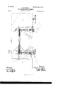
- Figure 1 shows a side elevation of so much of a separator and stacker with my improvements applied as is necessary to illustrate my invention
- Fig. 2 shows a plan view thereof with parts broken away.
- the separator A may be of any approved construction. I have only shown a portion of it, as my invention does not relate to any improvements in the construction of the sep arator proper.
- the same is true of the stacker B.
- the stacker is connected to the separator by a tongue 0. This tongue is secured to a cross-beam D, which is connected by suit able devices d to the front axle E.
- F indicates a fifth-wheel through which a king-bolt extends, and this fifth-Wheel is connected with the body of the stacker in the usual manner or in any desired way.
- the front end of the pole O is pivotally connected at c with a draw-bar G, which may be secured to the hind axle H of the separator, and it may be also secured and supported near its rear end by a hanger I, depending from the separator.
- a pulley J is arranged at one side .of the separator and near the rear end thereof. It may be belted or geared in any suitable way to the power-shaft or driving means. It is secured to a short shaft K, which has bearings in a bracket L, secured to the frame of the separator. To the shaft K is secured a shaft-section M, which has a universal joint or coupling N, with another short shaft-section 0.
- the shaft-section O is made square and enters a sleeve P, having a square bore, in which the shaft-section O is free to move lengthwise.
- the sleeve P is connected by a universal coupling Q with a short shaft R, having bearings in a bracket S, secured to the front end of the tongue or pole C.
- a pulley or sprocket-wheel T is secured to the shaft R between the bifurcated side pieces 3 of the bracket S.
- This pulley is connected by means of a chain or belt U with a sprocketwheel V on a short shaft 0, mounted in bearings in the upper end of the bracket W, which is mounted on or secured to the rear end of the tongue or pole O.
- the shaft 1 is connected by means of a universal joint or coupling X with the arm y of a sleeve Y, which has a square bore, into which extends a square shaft Z, connected by a universal joint or coupling a, with the arm I), projecting from a short shaft e, having bearings in a bracket f, secured to the frame of the stacker B.
- a pulley g is secured to the end of the shaft e.
- the separator may be drawn from place to place and drag the stacker after it, and power may be transmitted from the separator to the stacker no matter what may be the relative position of the stacker to the separator. It is not necessary to uncouple any parts of the gearing when moving the machines, as the gearing accommodates itself to any changes in relation between the two machines.
- the pulley or sprocket-Wheel V is arranged directly over the king-bolt of the stacker, while the pulley or sprocket-wheel T is arranged directly over the pivot a, connecting the front end of the pole with the separator.
- the gearing is adapted to flex or bend Vertically, if necessary, When traversing uneven ground, and it is adapted to flex or bend horizontally in the manner indicated in Fig. 2 when the machines are rounding a corner or when the position of one machine is changed relatively to the other.
Landscapes
- Life Sciences & Earth Sciences (AREA)
- Environmental Sciences (AREA)
- Micro-Organisms Or Cultivation Processes Thereof (AREA)
Description
No. 678,564. Patented July I6, mm.
W. n. HENDRY.
THRESHING IAGHINE ATTACHMENT.
(Application filed Apr. 19, 1901.) (N0 Model. 7
2 Sheeis-8heet l.
wit mow M. We. @4
WILLIAM R. HENDRY,
OF PAULLINA, IOW'A.
THRESHING-MACHINE ATTACHMENT.
SPECIFICATION forming part of Letters latent No. 678,564, dated July 16, 1901.
Application filed April 19 1901- Seriall No. 56 ,554- (No model.)
To all whom it may concern.-
Be it known thatLWILLIAM R. HENDRY, a citizen of the United States, residing at Paullina, in the county of OBrien and State of Iowa, have invented a certain new and useful Threshing-Machine Attachment, of which the following is a specification.
My invention relates to that class of threshing-machines in which an independent strawstacker is used in connection with a separator; and the object of my invention is to provide improved means for connecting the separator with the stacker, whereby the stacker may be drawn from place to place by the separator, and improved means for transmitting power from the separator to the stacker, which is so constructed and arranged that the gearing may be left in operative condition at all times and shall accommodate itself When the machines are being moved from place to place to inequalities in the ground and when turning corners or when the machines are placed at an angle to each other.
In carrying out my invention I connect the stacker to the separator by means of a pole or tongue which hasa pivotal connection with the separator, and I employ belt or chain gearing for transmitting power from the separator to the stacker. The belt or chain is arranged directly over the pole or tongue and passes over pulleys or sprocket-wheels, one of which is arranged directly over the kingbolt of the front axle of the stacker, while the other is arranged directly over the pivot at the front end of the tongue. A pulley or gearwheel is arranged at the rear end of the separator on one side, and this is connectedwith a pulley or sprocket-Wheel which is arranged over the front end of the tongue by means of a jointed shaft of an improved construction. The pulley or sprocket-Wheel of the stacker, which is arranged directly over the kingbolt, is connected by means of a jointed shaft with a pulley which is arranged at the front end and on one side of the stacker, the organization being such that power may be transmitted from the separator to the stacker at any time, no matter what may be the relative position of the stacker to the separator, and the stacker may be drawn from place to place over uneven ground or around corners without disturbing the gearing.
In the accompanying drawings, Figure 1 shows a side elevation of so much of a separator and stacker with my improvements applied as is necessary to illustrate my invention, and Fig. 2 shows a plan view thereof with parts broken away.
The separator A may be of any approved construction. I have only shown a portion of it, as my invention does not relate to any improvements in the construction of the sep arator proper. The same is true of the stacker B. The stacker is connected to the separator by a tongue 0. This tongue is secured to a cross-beam D, which is connected by suit able devices d to the front axle E.
F indicates a fifth-wheel through which a king-bolt extends, and this fifth-Wheel is connected with the body of the stacker in the usual manner or in any desired way.
The front end of the pole O is pivotally connected at c with a draw-bar G, which may be secured to the hind axle H of the separator, and it may be also secured and supported near its rear end by a hanger I, depending from the separator.
A pulley J is arranged at one side .of the separator and near the rear end thereof. It may be belted or geared in any suitable way to the power-shaft or driving means. It is secured to a short shaft K, which has bearings in a bracket L, secured to the frame of the separator. To the shaft K is secured a shaft-section M, which has a universal joint or coupling N, with another short shaft-section 0. The shaft-section O is made square and enters a sleeve P, having a square bore, in which the shaft-section O is free to move lengthwise. The sleeve P is connected by a universal coupling Q with a short shaft R, having bearings in a bracket S, secured to the front end of the tongue or pole C. A pulley or sprocket-wheel T is secured to the shaft R between the bifurcated side pieces 3 of the bracket S. This pulley is connected by means of a chain or belt U with a sprocketwheel V on a short shaft 0, mounted in bearings in the upper end of the bracket W, which is mounted on or secured to the rear end of the tongue or pole O. The shaft 1; is connected by means of a universal joint or coupling X with the arm y of a sleeve Y, which has a square bore, into which extends a square shaft Z, connected by a universal joint or coupling a, with the arm I), projecting from a short shaft e, having bearings in a bracket f, secured to the frame of the stacker B. A pulley g is secured to the end of the shaft e.
By this organization the separator may be drawn from place to place and drag the stacker after it, and power may be transmitted from the separator to the stacker no matter what may be the relative position of the stacker to the separator. It is not necessary to uncouple any parts of the gearing when moving the machines, as the gearing accommodates itself to any changes in relation between the two machines.
It will be observed that the pulley or sprocket-Wheel V is arranged directly over the king-bolt of the stacker, while the pulley or sprocket-wheel T is arranged directly over the pivot a, connecting the front end of the pole with the separator. The gearing is adapted to flex or bend Vertically, if necessary, When traversing uneven ground, and it is adapted to flex or bend horizontally in the manner indicated in Fig. 2 when the machines are rounding a corner or when the position of one machine is changed relatively to the other.
By the organization shownI am enabled to use sprocket-gearing, which has many advantages, and the machines may be placed with such relation to each other as to best accommodate them to the situation where they may be placed when at work.
I claim as my invention- 1. The combination of the separator, the
stacker, a pole or tongue connecting the separator and the stacker, a driving-pulley at the side of the separator, a pulley arranged over the front end of the tongue, a jointed shaft connecting the driving-pulley with the pulley arranged over the front end of the tongue, another pulleyarranged over the king-bolt of the stacker, a belt connecting the last-mentioned pulley with the pulley over the front end of the tongue, a pulley at the side of the stacker, and a jointed shaft connecting the pulley arranged over the king-bolt with the pulley at the side of the stacker. 2. The combination of the separator, the stacker, a pole connecting them, a pulley arranged over each end of the pole, a belt connecting these pulleys, pulleys at the side of the stacker and separator, and shafts connecting the pulleys at the sides of the separator and stacker with the pulleys arranged over the tongue, said shafts having sliding portions and universal couplings, substantially as described.
In testimony whereof I have hereunto subscribed my name.
WILLIAM R. HENDRY.
Witnesses:
RICHARD H. ARMOND, J. H. FISH.
Priority Applications (1)
| Application Number | Priority Date | Filing Date | Title |
|---|---|---|---|
| US5655401A US678564A (en) | 1901-04-19 | 1901-04-19 | Threshing-machine attachment. |
Applications Claiming Priority (1)
| Application Number | Priority Date | Filing Date | Title |
|---|---|---|---|
| US5655401A US678564A (en) | 1901-04-19 | 1901-04-19 | Threshing-machine attachment. |
Publications (1)
| Publication Number | Publication Date |
|---|---|
| US678564A true US678564A (en) | 1901-07-16 |
Family
ID=2747110
Family Applications (1)
| Application Number | Title | Priority Date | Filing Date |
|---|---|---|---|
| US5655401A Expired - Lifetime US678564A (en) | 1901-04-19 | 1901-04-19 | Threshing-machine attachment. |
Country Status (1)
| Country | Link |
|---|---|
| US (1) | US678564A (en) |
-
1901
- 1901-04-19 US US5655401A patent/US678564A/en not_active Expired - Lifetime
Similar Documents
| Publication | Publication Date | Title |
|---|---|---|
| US678564A (en) | Threshing-machine attachment. | |
| US1245168A (en) | Power-transmitting mechanism for tractors. | |
| US400270A (en) | Grain-elevator attachment for thrashing-machines | |
| US894439A (en) | Traveling thresher. | |
| US1640642A (en) | Tractor hitch | |
| US1455493A (en) | Drawbar and power attachment for tractors | |
| US819676A (en) | Grain-conveyer. | |
| US1159988A (en) | Tandem draft connection for harvesters. | |
| US464501A (en) | Charles j | |
| US1013894A (en) | Tandem draft connection for harvesters. | |
| US1395626A (en) | Flexible operating mechanism | |
| US1031065A (en) | Steering device for traction-vehicles. | |
| US573593A (en) | Traction-engine and harvester attachment | |
| US824840A (en) | Means for attaching and driving elevators. | |
| US129844A (en) | Improvement in coupling and steering apparatus | |
| US360514A (en) | Draft-equalizer for harvesters | |
| US692064A (en) | Motor-vehicle. | |
| US1269781A (en) | Binder attachment. | |
| US743424A (en) | Traction-engine. | |
| US995592A (en) | Machine for packing subsurface soil. | |
| US193697A (en) | Improvement in mowers | |
| US772222A (en) | Polishing-machine. | |
| US848990A (en) | Transit threshing-machine. | |
| US728451A (en) | Road-roller. | |
| US460126A (en) | Road-scraper |