US677757A - Wire-fence machine. - Google Patents
Wire-fence machine. Download PDFInfo
- Publication number
- US677757A US677757A US2219100A US1900022191A US677757A US 677757 A US677757 A US 677757A US 2219100 A US2219100 A US 2219100A US 1900022191 A US1900022191 A US 1900022191A US 677757 A US677757 A US 677757A
- Authority
- US
- United States
- Prior art keywords
- machine
- twister
- staples
- fastening
- wire
- Prior art date
- Legal status (The legal status is an assumption and is not a legal conclusion. Google has not performed a legal analysis and makes no representation as to the accuracy of the status listed.)
- Expired - Lifetime
Links
- RLLPVAHGXHCWKJ-IEBWSBKVSA-N (3-phenoxyphenyl)methyl (1s,3s)-3-(2,2-dichloroethenyl)-2,2-dimethylcyclopropane-1-carboxylate Chemical compound CC1(C)[C@H](C=C(Cl)Cl)[C@@H]1C(=O)OCC1=CC=CC(OC=2C=CC=CC=2)=C1 RLLPVAHGXHCWKJ-IEBWSBKVSA-N 0.000 description 6
- 229910000746 Structural steel Inorganic materials 0.000 description 2
- 238000010276 construction Methods 0.000 description 2
- 238000004519 manufacturing process Methods 0.000 description 2
- 241001589086 Bellapiscis medius Species 0.000 description 1
- 230000004048 modification Effects 0.000 description 1
- 238000012986 modification Methods 0.000 description 1
Images
Classifications
-
- B—PERFORMING OPERATIONS; TRANSPORTING
- B65—CONVEYING; PACKING; STORING; HANDLING THIN OR FILAMENTARY MATERIAL
- B65H—HANDLING THIN OR FILAMENTARY MATERIAL, e.g. SHEETS, WEBS, CABLES
- B65H49/00—Unwinding or paying-out filamentary material; Supporting, storing or transporting packages from which filamentary material is to be withdrawn or paid-out
- B65H49/18—Methods or apparatus in which packages rotate
- B65H49/20—Package-supporting devices
- B65H49/32—Stands or frameworks
Definitions
- My invention relates to a machine for use loops, the horizontal strands and vertical pickets being united by fastening wires or staples, the ends of which are twisted around the horizontal strands.
- the several loops in such vertical stays or pickets are formed simultaneously, and at the time the loops are formed the fastening wires or staples for securing the stays or pickets to the horizontal strands are placed within the loops by means of a machine designed by me and described in Letters Patent No. 642,296, granted J anuary 30, 1900.
- My present machine which is portable, is designed for use in rapidly putting up or erecting the fence, and in operation holds the stay or picket after it has been looped and provided with the fastening wires or staples by my said machine, when by pressing against the strands which have been previously secured to the fence-posts and revolving a crank all the fastening wires or staples will be simultaneously coiled or twisted around the horizontal strands, whereby the stay or picket will by one action or4 operation be attached to the lseries of horizontal strands, thus increas-A 5, on the other side of said support.
- Igears 4 5 are radially slotted, as shown at 6 v7, for a purpose hereinafter described.
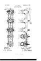
- Figure 1 is a face view of my improved stay-attaching machine.
- Fig. 2 is a side elevation of the same.
- Fig. 3 is a top view.
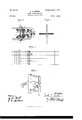
- Fig. 4 shows the attachment of a vertical looped picket and a horizontal strand by means of a fastening wire or staple.
- Fig. 5 is a view, upon a reduced scale, 'of a panel of fencing of the kind covered by Letters Patent No. 588,896 and illustrating the use of myinvention. fication hereinafter described.
- each of the U-shaped supports 3 is slotted, as shown at 4', each slot at its outer end terminating in a widened or enlarged mouth, as shown in Figs. 2 and 6.
- gears 4 5 are driven in opposite directions by means of a miter gear 8, (see particularly Fig. 3,) mounted upon a shaft 9, having bearings in the inner or connecting portion of the U-shaped support 3 and the bracket 1 2, respectively, said shaft being provided at its outer end with a squared portion to receive a crank 10.
- a series of these shafts 9, each shaft is
- a modiouter endof the bracket 12 supports a guide 18, and each gear 4 or 5 carries at its inner side, suitably bolted or secured thereto, a twister-point 14 or 15, 14 being attached to one gear of the pair and the point 15 to the other gear coperating therewith.
- each loop carrying its fastening wire or staple is held up against the series of horizontal strands and the machine slipped over or past said strands, which enter the slots of the U-shaped support 3.
- the ends of each fastening wire or staple will be caught by the twister-points of the gears 4 and 5, respectively, which are rotated in opposite directions and twisted around the horizontal strands, the result being the production of the connection shown in Fig. 4.
- the guide 13, secured to the bracket, is intended to prevent the ends of the fastening-wire from getting caught in the gearing, as will be readily understood.
- twisterpoints 14 or 15 The construction of the twisterpoints 14 or 15 is such as to give the necessary twisting action to the fastening wire or staple as the gears are rotated in opposite directions. It will be understood that the action of all the twister-heads carried by the frame (by which I mean the entire mechanism, including the gearing employed in giving the twist to each of the fastening wires or staples) is coincident. In other words, all the fastening wires or staples passed through the several loops of the pickets are simultaneously twisted in opposite directions, each at the respective side of its loop around the horizontal strands.
- each end of each fastening wire or staple havingY been reached in the ro- I tation of the gearing the twister-points are necessarily disengaged from such ends, and the fastening-Wires being of equal length at the several loops all the twister-points become released from the ends of the fasteningwires simultaneously.
- the slotting of the gears 4 and 5, as shown at 6, is necessary to allow the machine to be pushed over the horizontal strands preparatory to the twisting action.
- the number of twister-heads will be varied in accordance with the number of horizontal strands of wire attached to the fence-posts.
- the supports 3, carrying the twister-heads, are adj ustably secured to the frame, so as to be adapted to be changed in position to suit the spacing of the horizontal strands.
- slots 16 are provided in the frame, acting in conjunction with the securing-bolts 17.
- My invention is capable of modifications in construction,as in the character of the frame, which may be of channel-iron-as shown, for example, in Figs. 1 and 2-or of angle-iron 1', as seen in Fig. 6.
- the mode of supporting the gearing may also be varied and other unimportant changes', which will readily suggest themselves to the skilled mechanic, made without departing from my invention.
- I claim- 1 In a machine of the character described, the combination of a frame, a series of twister-heads mounted therein comprising gearing adapted to be rotated in opposite directions and to operate upon the fastening wires or staples, and means for preventing the entanglement of the ends of the fastening wires or staples in the gearing, substantially as set ⁇ forth.
- a frame a series of twister-heads mounted therein comprising gearing adapted to be rotated in opposite directions and to act upon the fastening wires or staples, means for preventing the entanglement of the ends of the fastening wires or staples in the gearing, and means for simultaneously rotating the series of twister-heads, substantially as set forth.
Landscapes
- Wire Processing (AREA)
Description
Patented luly 2, |901.
C. C. CARTER.
WIRE FENCE MACHlNE.
(No Model.)
[Appl-kation led June 30, 1900;)
2 Sheets-Sheet I.
www@
1m: mums Pains cn.. mow-uws., wAsHmsfoN. D c,
No. 677,757. Patented luly 2, I90I. C. C. CARTER.
wlRE FENCE MACHINE.
(Application led .Tune 30, 1900.)
(No Model.) 2 Sheets-Sheet 2.
5gg. 5. 159i f* y n I I l UM/vento@ @www E) M r 5% 'UNITED STATES PATENT OFFICE.
CURTIS C. CARTER, OF JACKSONVILLE, ILLINOIS.
WIRE-FENCE MACHINE.
SPECIFICATION forming part of Letters Patent No. 677,757, dated July 2, 1901. Application filed June 30, 1900. Serial No. 22,191. (No model.)
To all whom t may concern:
Be it known that I, CURTIS C. CARTER, a
citizen of the United States, residing at Jacksonville, in the county of Morgan and State of Illinois, have invented a new and useful Improvement in Wire -Fence Machines, of which the following is a specification, reference being had to the accompanying drawings and to the numerals of reference marked thereon.
My invention relates to a machine for use loops, the horizontal strands and vertical pickets being united by fastening wires or staples, the ends of which are twisted around the horizontal strands. The several loops in such vertical stays or pickets are formed simultaneously, and at the time the loops are formed the fastening wires or staples for securing the stays or pickets to the horizontal strands are placed within the loops by means of a machine designed by me and described in Letters Patent No. 642,296, granted J anuary 30, 1900. By the use of my said machine the manufacture of such a fence as is described in the aforementioned Letters Patent No. 588,896, granted to Cyrus C. Carter, is facilitated and cheapened, and the work done is stronger and more uniform in its character than similar work done by hand.
My present machine, which is portable, is designed for use in rapidly putting up or erecting the fence, and in operation holds the stay or picket after it has been looped and provided with the fastening wires or staples by my said machine, when by pressing against the strands which have been previously secured to the fence-posts and revolving a crank all the fastening wires or staples will be simultaneously coiled or twisted around the horizontal strands, whereby the stay or picket will by one action or4 operation be attached to the lseries of horizontal strands, thus increas-A 5, on the other side of said support. Igears 4 5 are radially slotted, as shown at 6 v7, for a purpose hereinafter described. The
ingthespeed of erectionof the fence and at the same time insuring a tight, efficient, and uniform fastening' of the Vertical stays or pickets to the horizontal strands.
In the accompanying drawings, Figure 1 is a face view of my improved stay-attaching machine. Fig. 2 is a side elevation of the same. Fig. 3 is a top view. Fig. 4 shows the attachment of a vertical looped picket and a horizontal strand by means of a fastening wire or staple. Fig. 5 is a view, upon a reduced scale, 'of a panel of fencing of the kind covered by Letters Patent No. 588,896 and illustrating the use of myinvention. fication hereinafter described.
Similar numerals of reference indicate simi-A lar parts in the respective figures.
l l represent the frame of the machine, consisting, preferably, of channel-iron, and secured to the frame is a series of U-shaped supports 3, one for each of the horizontal strands of the fence to be erected and carrying the device, termed the twister-head, for making the connection between the picket and the strands. Each member of each of the U-shaped supports 3 is slotted, as shown at 4', each slot at its outer end terminating in a widened or enlarged mouth, as shown in Figs. 2 and 6.
For convenience in description I will de-I scribe but one of the U-shaped supports 3, with its accompanying mechanism, all of the said supports,with theiradj uncts,being alike. Each of the parallel members of the support forms a bearing for the short shaft of a mitergear 4 or 5, 4 being on one side and the other, The
Fig. Gis a modiouter endof the bracket 12 supports a guide 18, and each gear 4 or 5 carries at its inner side, suitably bolted or secured thereto, a twister- point 14 or 15, 14 being attached to one gear of the pair and the point 15 to the other gear coperating therewith.
In operation, the horizontal strands having been previously secured to the fence-posts,
when it is desired to attach the looped pickets in succession to the series of horizontal strands alooped picket, each loop carrying its fastening wire or staple, is held up against the series of horizontal strands and the machine slipped over or past said strands, which enter the slots of the U-shaped support 3. In the position shown in Fig. 8 the ends of each fastening wire or staple will be caught by the twister-points of the gears 4 and 5, respectively, which are rotated in opposite directions and twisted around the horizontal strands, the result being the production of the connection shown in Fig. 4. The guide 13, secured to the bracket, is intended to prevent the ends of the fastening-wire from getting caught in the gearing, as will be readily understood. The construction of the twisterpoints 14 or 15 is such as to give the necessary twisting action to the fastening wire or staple as the gears are rotated in opposite directions. It will be understood that the action of all the twister-heads carried by the frame (by which I mean the entire mechanism, including the gearing employed in giving the twist to each of the fastening wires or staples) is coincident. In other words, all the fastening wires or staples passed through the several loops of the pickets are simultaneously twisted in opposite directions, each at the respective side of its loop around the horizontal strands. Each end of each fastening wire or staple havingY been reached in the ro- I tation of the gearing, the twister-points are necessarily disengaged from such ends, and the fastening-Wires being of equal length at the several loops all the twister-points become released from the ends of the fasteningwires simultaneously.
The operation described having been eected, the machine is withdrawn from the horizontal strands to be used for the attachment of another picket thereto.
The slotting of the gears 4 and 5, as shown at 6, is necessary to allow the machine to be pushed over the horizontal strands preparatory to the twisting action. The number of twister-heads will be varied in accordance with the number of horizontal strands of wire attached to the fence-posts. The supports 3, carrying the twister-heads, are adj ustably secured to the frame, so as to be adapted to be changed in position to suit the spacing of the horizontal strands. For this purpose slots 16 are provided in the frame, acting in conjunction with the securing-bolts 17.
My invention is capable of modifications in construction,as in the character of the frame, which may be of channel-iron-as shown, for example, in Figs. 1 and 2-or of angle-iron 1', as seen in Fig. 6. The mode of supporting the gearing may also be varied and other unimportant changes', which will readily suggest themselves to the skilled mechanic, made without departing from my invention.
I claim- 1. In a machine of the character described, the combination of a frame, a series of twister-heads mounted therein comprising gearing adapted to be rotated in opposite directions and to operate upon the fastening wires or staples, and means for preventing the entanglement of the ends of the fastening wires or staples in the gearing, substantially as set `forth.
2. In a machine of the character described, the combination of a frame, a series of twister-heads mounted therein comprising gearing adapted to be rotated in opposite directions and to act upon the fastening wires or staples, means for preventing the entanglement of the ends of the fastening wires or staples in the gearing, and means for simultaneously rotating the series of twister-heads, substantially as set forth.
3. In a machine of the character described, the combination of a frame, a series of twister-heads mounted therein, comprising gearing adapted to be rotated in opposite directions and to twist the fastening wires or staples upon the horizontal strands, and means for preventing the entanglement of the ends of the fastening wires or staples in the gearing, substantially as set forth.
4.. In a machine of the character described, the combination of a frame, a series of twister-heads mounted therein comprising slotted gearing adapted to be rotated in opposite directions and Vto act upon the fastening wires or staples, means for preventing the entanglement of the ends of the fastening wires or staples in the gearing, and means for simultaneously rotating the series of twister-heads, substantially as set forth.
5. In a machine of the character described, the combination of a frame, slotted U-shaped supports attached thereto, twister-heads carried by said supports comprising gearing adapted to be rotated in'opposite directions and to twist the fastening wires or staples upon the horizontal strands, means for preventing the entanglement of the ends of the IOO IIO
fastening wires or staples in the gearing, and means for simultaneously rotating the series of twister-heads, substantially as set forth.
6. In a machine of the character described, the combination of a frame, slotted U-shaped su pports adj ustably attached thereto,twister heads carried by said supports, means for simultaneously rotating the series of twisterheads, and means for preventing the entanglement of the ends of the fastening wires or 1o staples in the gearing, substantially as set forth.
In testimony whereof I hereunto set my hand.
CURTIS C. CARTER. Witnesses:
ANNIE T. LOAR, ELMER E. HORTON.
Priority Applications (1)
| Application Number | Priority Date | Filing Date | Title |
|---|---|---|---|
| US2219100A US677757A (en) | 1900-06-30 | 1900-06-30 | Wire-fence machine. |
Applications Claiming Priority (1)
| Application Number | Priority Date | Filing Date | Title |
|---|---|---|---|
| US2219100A US677757A (en) | 1900-06-30 | 1900-06-30 | Wire-fence machine. |
Publications (1)
| Publication Number | Publication Date |
|---|---|
| US677757A true US677757A (en) | 1901-07-02 |
Family
ID=2746304
Family Applications (1)
| Application Number | Title | Priority Date | Filing Date |
|---|---|---|---|
| US2219100A Expired - Lifetime US677757A (en) | 1900-06-30 | 1900-06-30 | Wire-fence machine. |
Country Status (1)
| Country | Link |
|---|---|
| US (1) | US677757A (en) |
-
1900
- 1900-06-30 US US2219100A patent/US677757A/en not_active Expired - Lifetime
Similar Documents
| Publication | Publication Date | Title |
|---|---|---|
| US677757A (en) | Wire-fence machine. | |
| US473930A (en) | Fence-machine | |
| US309724A (en) | Portable fence-machine | |
| US415843A (en) | Fence-machine | |
| USRE10687E (en) | Portable fence-machine | |
| US583782A (en) | Half to joseph harris | |
| US557542A (en) | Fence-machine | |
| US387860A (en) | Fence-machine | |
| US372650A (en) | Fence-machine | |
| US562452A (en) | Fence-making machine | |
| US405890A (en) | Machine for building | |
| US471571A (en) | Tension device | |
| US524612A (en) | Machine for wiring fence-pickets | |
| US347064A (en) | Ntdiasta | |
| US653719A (en) | Wire-fence machine. | |
| US704396A (en) | Fence-making machine. | |
| US417279A (en) | Fence-machine | |
| US513371A (en) | Fence-machine | |
| US563117A (en) | Fence-machine | |
| US560734A (en) | Slat-and-wire-fence machine | |
| US27923A (en) | Improved machine for making picket-fence | |
| US743806A (en) | Wire-fence machine. | |
| US739520A (en) | Fence-machine. | |
| US551204A (en) | Wire-fence-weaving machine | |
| US410706A (en) | Fence-machine |