US677191A - Electric controller. - Google Patents
Electric controller. Download PDFInfo
- Publication number
- US677191A US677191A US4622301A US1901046223A US677191A US 677191 A US677191 A US 677191A US 4622301 A US4622301 A US 4622301A US 1901046223 A US1901046223 A US 1901046223A US 677191 A US677191 A US 677191A
- Authority
- US
- United States
- Prior art keywords
- pieces
- contact
- electric controller
- brushes
- controller
- Prior art date
- Legal status (The legal status is an assumption and is not a legal conclusion. Google has not performed a legal analysis and makes no representation as to the accuracy of the status listed.)
- Expired - Lifetime
Links
Images


Classifications
-
- H—ELECTRICITY
- H01—ELECTRIC ELEMENTS
- H01H—ELECTRIC SWITCHES; RELAYS; SELECTORS; EMERGENCY PROTECTIVE DEVICES
- H01H15/00—Switches having rectilinearly-movable operating part or parts adapted for actuation in opposite directions, e.g. slide switch
- H01H15/005—Switches having rectilinearly-movable operating part or parts adapted for actuation in opposite directions, e.g. slide switch adapted for connection with printed circuit boards
Definitions
- My invention relates to certain improve ments in controllers for electric motors, having for its object the provision of a device of the character described in which all parts shall be readily accessible for-inspection and repairs and that without in any way disturbing any of the other parts thereof.
- Fig. 2 is an end View of the same.
- Fig. 3 is a plan view, the operating-lever being removed.
- Fig. 4 is a diagram of the connections when my improved controller is used in connection with one motor
- Fig. 5 is a diagram of the connections when the construction'of the controller is modified to have two instead of four series of contact-plates.
- A is the frame of the apparatus, consisting of an upper plate and a base-plate and standards CL CL.
- a box-like casting A On the upper plate is mounted a box-like casting A, preferably held to the upper plate by the standards, whichare threaded at the ends and are provided with nuts, as shown.
- This casting has end pieces a a, constructed to receive a cover (not shown) for the protection of parts hereinafter described.
- Bars 13 B are bolted to and extend between the upper and the base plate, and on these are supported resistance-coils b b, preferably of the form shown anddescribed in my application filed December 13, 1900, Serial No. 39,739. Said coils are constructed to have both terminals at one end, each one having pieces I), from which it is insulated and'which are screwed or bolted to-the bars B B.
- a plate 0,015 slate, marble, or other insulating material on which in the present instance four series of contact-pieces c c are mounted. These are electrically connected to each other and to the various resistancecoils b b in any desirable combination, being held on the insulating-plate C in such a way as to be readily removed or replaced without disturbing any part of the apparatus but that being directly operated upon.
- a rod or guide-bar ed Supported by the end extensions ct a of the piece A is a rod or guide-bar ed, on which the tubular part or cross-head d of a brushholder arm D is constructed to slide.
- This arm consists of sections (1' (1, extending laterally from the cross-head d and having connected to them brush-holders E E, in the present instance of the style shown and described in anapplication for patent filed by me De- ,cember 3, 1900, Serial No. 38,482.
- the lateral extensions 01' d are continued past the brusha holders and have their ends constructed to move in slots f of an operating-lever F.
- this lever is U-shaped, having its ends pivoted to the base-plate of the controller at f and with a handle f
- the slots ff are elongated to allow of motion of the ends of the brush-holder arm therein, due to the circular path traveled in by the operating-lever as it is moved under working conditions.
- a terminal plate 0, of insulating material is bolted to the upright bars B B, having on it four terminals g g g 9 which in operation would be connected, respectively, to the line, the two armature-terminals of the motor, and to one of the field-terminals, as indicated in Fig. l.
- Each of the brush-holdersE has two brushes electrically insulated from the arm D, but connected to each other either directly or through the magnet of said holder.
- the operating-lever When not in use, the operating-lever stands vertically, the brushes resting on the fiber blocks or segments 0 o. By moving the said lever in one direction from this position the brushes. first pass over dead-segments c c and then come in Contact with the pieces 0 0, thus starting a motor properly connected in circuit. At first the resistance is all in, as is seen from inspection of the diagram in Fig. 4, and this may be gradually cut out and the motor speeded up by moving the handle farther from the mid-position.
- the connections in the controller are so made that by moving o c, as indicated in Big. 5, which shows the connections of the modification described.
- controllers may be. placed side by side without space between them, as is necessary in the cab of a crane, for instance, without interfering with the ease of inspection, &c. That this is possible is due to the fact that the contact-pieces are on top of the controller and that the coils may be removed from the front. In taking out a coil all that is necessary is -to remove the screw holding the pieces I) to that bar 13 and to draw the coil out, the back end of each one being constructed to be loosely held in a hole in the back set of bars B.
- an electric controller the combination of a frame, contact-plates supported thereby, an operating-lever pivoted to said frame, a guide-bar supported on the frame,
- a brush-holder arm sliding on said bar and having ends constructedto enter slots in the operating-lever, and brushes on the said arm constructed to form electrical contact with the contact-pieces,substantiall y as described.
Description
No. 677,l9l. V Patented June 25, I9DI. A. C, EASTWOOD.
- ELECTRIC CONTROLLER.
(Application filed. Feb. 6, 1901.) (No Model.) 3 Sheets-Sheet l.
Ll llllvl F C "B 01 D in ms PETERS 00,, wanna wmmurol. n40
N0. amen. V Patented 1 25, l90l.
A; c. EASTWOOD. ELECTRIC CONTROLLER.
(Application filed Fab. 6, 1901.) (No Model.) 7 3 Shoots-Shoot 2;
m: NORRIS PETEFIS w. PNOYO-LITHQ. WASHINUYON. p. c,
No. 677,l9l'. I P atnted June 25, 190i. A. c EASTWOOD. ELECTRIC CONTROLLER.
(Applicntion Med Feb. 6. 190:.)
(No Iodal.) 3 She'ois-Sheet 3. g
H v lime/I or:
ywaw
m5 Norms PEYERS coy, PnoroLwun. WASNINGTGN, '0. cv
UNITED STATES PATENT OFFICE.
ARTHUR C. EASTWOOD, on CLEVELAND, oI-no.
ELECTRIC CONTROLLER.
SPECIFICATION forming part of Letters Patent No. 677,191, dated June 25, 1901. Application filed February 6, 1901. Serial No. 46,223. (No model.)
of Cleveland, Ohio, have invented certain Im-' provements in Electric Controllers, of which thefollowing is a specification.
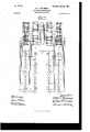
My invention relates to certain improve ments in controllers for electric motors, having for its object the provision of a device of the character described in which all parts shall be readily accessible for-inspection and repairs and that without in any way disturbing any of the other parts thereof. This object I attain as hereinafter set forth, reference being had to the accompanying drawings, in which- I Figure 1 is a side view of myimproved controller with the covers removed to show the arrangement of the parts. Fig. 2 is an end View of the same. Fig. 3 is a plan view, the operating-lever being removed. Fig. 4 is a diagram of the connections when my improved controller is used in connection with one motor, and Fig. 5 is a diagram of the connections when the construction'of the controller is modified to have two instead of four series of contact-plates.
In the drawings, A is the frame of the apparatus, consisting of an upper plate and a base-plate and standards CL CL. On the upper plate is mounted a box-like casting A, preferably held to the upper plate by the standards, whichare threaded at the ends and are provided with nuts, as shown. This casting has end pieces a a, constructed to receive a cover (not shown) for the protection of parts hereinafter described.
Bars 13 B are bolted to and extend between the upper and the base plate, and on these are supported resistance-coils b b, preferably of the form shown anddescribed in my application filed December 13, 1900, Serial No. 39,739. Said coils are constructed to have both terminals at one end, each one having pieces I), from which it is insulated and'which are screwed or bolted to-the bars B B.
Bolted to the upper face of the casting A is a plate 0,015 slate, marble, or other insulating material, on which in the present instance four series of contact-pieces c c are mounted. These are electrically connected to each other and to the various resistancecoils b b in any desirable combination, being held on the insulating-plate C in such a way as to be readily removed or replaced without disturbing any part of the apparatus but that being directly operated upon.
Supported by the end extensions ct a of the piece A is a rod or guide-bar ed, on which the tubular part or cross-head d of a brushholder arm D is constructed to slide. This arm consists of sections (1' (1, extending laterally from the cross-head d and having connected to them brush-holders E E, in the present instance of the style shown and described in anapplication for patent filed by me De- ,cember 3, 1900, Serial No. 38,482. The lateral extensions 01' d are continued past the brusha holders and have their ends constructed to move in slots f of an operating-lever F. In the preferred form of my invention this lever is U-shaped, having its ends pivoted to the base-plate of the controller at f and with a handle f The slots ff are elongated to allow of motion of the ends of the brush-holder arm therein, due to the circular path traveled in by the operating-lever as it is moved under working conditions.
In the construction shown a terminal plate 0, of insulating material, is bolted to the upright bars B B, having on it four terminals g g g 9 which in operation would be connected, respectively, to the line, the two armature-terminals of the motor, and to one of the field-terminals, as indicated in Fig. l.
Each of the brush-holdersE has two brushes electrically insulated from the arm D, but connected to each other either directly or through the magnet of said holder.
When not in use, the operating-lever stands vertically, the brushes resting on the fiber blocks or segments 0 o. By moving the said lever in one direction from this position the brushes. first pass over dead-segments c c and then come in Contact with the pieces 0 0, thus starting a motor properly connected in circuit. At first the resistance is all in, as is seen from inspection of the diagram in Fig. 4, and this may be gradually cut out and the motor speeded up by moving the handle farther from the mid-position. The connections in the controller are so made that by moving o c, as indicated in Big. 5, which shows the connections of the modification described.
It will be seen that from the construction. herein set forth all parts that could possibly require repairs or replacement are so placed and constructed as to be easily accessible,
' making it possible to remove any such part Without involving unnecessary labor or disturbance of adjacent parts.
It will be further noted that a number of controllers may be. placed side by side without space between them, as is necessary in the cab of a crane, for instance, without interfering with the ease of inspection, &c. That this is possible is due to the fact that the contact-pieces are on top of the controller and that the coils may be removed from the front. In taking out a coil all that is necessary is -to remove the screw holding the pieces I) to that bar 13 and to draw the coil out, the back end of each one being constructed to be loosely held in a hole in the back set of bars B.
I claim as my invention 1. In an electric controller, the combination of a frame, contact-plates supported thereby, an operating-lever pivoted to said frame, a guide-bar supported on the frame,
' a brush-holder arm sliding on said bar and having ends constructedto enter slots in the operating-lever, and brushes on the said arm constructed to form electrical contact with the contact-pieces,substantiall y as described.
2. In an electric controller, the combination of a frame, resistance-coils supported in a horizontal position therein, and in such manner that any coil may be removed from the front of the controller independently of contact-pieces connected to the said coils, brushes constructed to be moved over said contact-pieces and means for so moving said brushes, substantially as the same, a plate of insulating material, a
number ofseries of contact-pieces on said plate, a guide-bar supported over the plate, and parallel with the series of contacts, a brush-holder arm having brushes, said arm sliding on the guide-bar and a lever for movingsaid arm with its brushes over the con-. tact-pieces, substantially as described.
4. In an electric controller, the combination of a frame, resistance-coils thereon, contact-pieces electrically connected to said coils, a stationary guide-barsupported by the frame and extending over the contact-pieces,a crosshead movable on said guide-bar, lateral extensions on the cross-head and brush-holders carrying brushes connected to said extensions movable over the contact-pieces, with means applied to the ends of said lateral extensions for moving the cross-head with the brushes, substantially as described.
5. The combination in an electric controller, of'a frame, contact-pieces supported thereon, brushes constructed to be moved over said contact-pieces, brush-holders and a supporting-arm therefor, and a U-shaped lever pivoted to the frame and looselyconnected to the supportfor the brush-holder arm, resistance-coils supported on the frame and connected to the contact-pieces substantially as described.
6. In a supporting-frame for an electric controller, the combination of top and bottom plates, standards between the same, pieces for supporting resistance-coils also extending between the plates, resistance-coils constructed to fit loosely into one set of vertical supporting-bars and to be rigidly attached to the second set of the same, substantially as described.
In testimony whereof I have signed my name to this specification in the presence of two subscribing witnesses.
ARTHUR C. EASTWOOD.v Witnesses:
O. W. COMSTOCK, HERBERT D. GLIDDEN.
Priority Applications (1)
| Application Number | Priority Date | Filing Date | Title |
|---|---|---|---|
| US4622301A US677191A (en) | 1901-02-06 | 1901-02-06 | Electric controller. |
Applications Claiming Priority (1)
| Application Number | Priority Date | Filing Date | Title |
|---|---|---|---|
| US4622301A US677191A (en) | 1901-02-06 | 1901-02-06 | Electric controller. |
Publications (1)
| Publication Number | Publication Date |
|---|---|
| US677191A true US677191A (en) | 1901-06-25 |
Family
ID=2745738
Family Applications (1)
| Application Number | Title | Priority Date | Filing Date |
|---|---|---|---|
| US4622301A Expired - Lifetime US677191A (en) | 1901-02-06 | 1901-02-06 | Electric controller. |
Country Status (1)
| Country | Link |
|---|---|
| US (1) | US677191A (en) |
Cited By (1)
| Publication number | Priority date | Publication date | Assignee | Title |
|---|---|---|---|---|
| AU2012211519B2 (en) * | 2011-02-02 | 2015-07-30 | Medipost Co., Ltd. | Use of ICAM-1 for prevention or treatment of neurological diseases |
-
1901
- 1901-02-06 US US4622301A patent/US677191A/en not_active Expired - Lifetime
Cited By (2)
| Publication number | Priority date | Publication date | Assignee | Title |
|---|---|---|---|---|
| AU2012211519B2 (en) * | 2011-02-02 | 2015-07-30 | Medipost Co., Ltd. | Use of ICAM-1 for prevention or treatment of neurological diseases |
| AU2012211519A9 (en) * | 2011-02-02 | 2015-07-30 | Medipost Co., Ltd. | Use of ICAM-1 for prevention or treatment of neurological diseases |
Similar Documents
| Publication | Publication Date | Title |
|---|---|---|
| US677191A (en) | Electric controller. | |
| US976549A (en) | Switch. | |
| US1233959A (en) | Motor-controller. | |
| US699506A (en) | Electric controller. | |
| US1016329A (en) | Multiple-circuit controller. | |
| US1164001A (en) | Electric-circuit controller. | |
| US988245A (en) | Oil-switch. | |
| US731298A (en) | Electric controller. | |
| US800916A (en) | High-potential switch. | |
| US445741A (en) | Franklin a | |
| US520788A (en) | And edwin pl | |
| US508692A (en) | Rheostat for controlling electrically-operated dental apparatus | |
| US561588A (en) | Electric switch | |
| US1138659A (en) | Resistance device. | |
| US756711A (en) | Electric controller for alternating currents. | |
| US535511A (en) | Electrical controller | |
| US772313A (en) | Electric controller | |
| US609188A (en) | kingsland | |
| US721372A (en) | Electric controller. | |
| US907108A (en) | Insulator for circuit-breakers. | |
| US746669A (en) | Current-regulator. | |
| US496901A (en) | Switchboard for electric circuits | |
| US1104758A (en) | Electric starter for motors, alternating or direct current. | |
| US384116A (en) | Electric shunting device | |
| US930156A (en) | Oil-switch. |