US6764070B2 - Pathlength compensation method and device for high speed sheet cutters - Google Patents
Pathlength compensation method and device for high speed sheet cutters Download PDFInfo
- Publication number
- US6764070B2 US6764070B2 US10/280,382 US28038202A US6764070B2 US 6764070 B2 US6764070 B2 US 6764070B2 US 28038202 A US28038202 A US 28038202A US 6764070 B2 US6764070 B2 US 6764070B2
- Authority
- US
- United States
- Prior art keywords
- path
- sheet
- sheets
- length
- point
- Prior art date
- Legal status (The legal status is an assumption and is not a legal conclusion. Google has not performed a legal analysis and makes no representation as to the accuracy of the status listed.)
- Expired - Lifetime, expires
Links
Images


Classifications
-
- B—PERFORMING OPERATIONS; TRANSPORTING
- B65—CONVEYING; PACKING; STORING; HANDLING THIN OR FILAMENTARY MATERIAL
- B65H—HANDLING THIN OR FILAMENTARY MATERIAL, e.g. SHEETS, WEBS, CABLES
- B65H29/00—Delivering or advancing articles from machines; Advancing articles to or into piles
- B65H29/66—Advancing articles in overlapping streams
- B65H29/6609—Advancing articles in overlapping streams forming an overlapping stream
-
- B—PERFORMING OPERATIONS; TRANSPORTING
- B65—CONVEYING; PACKING; STORING; HANDLING THIN OR FILAMENTARY MATERIAL
- B65H—HANDLING THIN OR FILAMENTARY MATERIAL, e.g. SHEETS, WEBS, CABLES
- B65H35/00—Delivering articles from cutting or line-perforating machines; Article or web delivery apparatus incorporating cutting or line-perforating devices, e.g. adhesive tape dispensers
- B65H35/02—Delivering articles from cutting or line-perforating machines; Article or web delivery apparatus incorporating cutting or line-perforating devices, e.g. adhesive tape dispensers from or with longitudinal slitters or perforators
-
- B—PERFORMING OPERATIONS; TRANSPORTING
- B65—CONVEYING; PACKING; STORING; HANDLING THIN OR FILAMENTARY MATERIAL
- B65H—HANDLING THIN OR FILAMENTARY MATERIAL, e.g. SHEETS, WEBS, CABLES
- B65H35/00—Delivering articles from cutting or line-perforating machines; Article or web delivery apparatus incorporating cutting or line-perforating devices, e.g. adhesive tape dispensers
- B65H35/04—Delivering articles from cutting or line-perforating machines; Article or web delivery apparatus incorporating cutting or line-perforating devices, e.g. adhesive tape dispensers from or with transverse cutters or perforators
-
- B—PERFORMING OPERATIONS; TRANSPORTING
- B65—CONVEYING; PACKING; STORING; HANDLING THIN OR FILAMENTARY MATERIAL
- B65H—HANDLING THIN OR FILAMENTARY MATERIAL, e.g. SHEETS, WEBS, CABLES
- B65H39/00—Associating, collating, or gathering articles or webs
- B65H39/02—Associating,collating or gathering articles from several sources
- B65H39/06—Associating,collating or gathering articles from several sources from delivery streams
-
- B—PERFORMING OPERATIONS; TRANSPORTING
- B65—CONVEYING; PACKING; STORING; HANDLING THIN OR FILAMENTARY MATERIAL
- B65H—HANDLING THIN OR FILAMENTARY MATERIAL, e.g. SHEETS, WEBS, CABLES
- B65H2301/00—Handling processes for sheets or webs
- B65H2301/30—Orientation, displacement, position of the handled material
- B65H2301/34—Modifying, selecting, changing direction of displacement
- B65H2301/342—Modifying, selecting, changing direction of displacement with change of plane of displacement
- B65H2301/3423—Modifying, selecting, changing direction of displacement with change of plane of displacement by travelling an angled curved path section for overturning and changing feeding direction
-
- B—PERFORMING OPERATIONS; TRANSPORTING
- B65—CONVEYING; PACKING; STORING; HANDLING THIN OR FILAMENTARY MATERIAL
- B65H—HANDLING THIN OR FILAMENTARY MATERIAL, e.g. SHEETS, WEBS, CABLES
- B65H2301/00—Handling processes for sheets or webs
- B65H2301/40—Type of handling process
- B65H2301/44—Moving, forwarding, guiding material
- B65H2301/445—Moving, forwarding, guiding material stream of articles separated from each other
- B65H2301/4454—Merging two or more streams
-
- B—PERFORMING OPERATIONS; TRANSPORTING
- B65—CONVEYING; PACKING; STORING; HANDLING THIN OR FILAMENTARY MATERIAL
- B65H—HANDLING THIN OR FILAMENTARY MATERIAL, e.g. SHEETS, WEBS, CABLES
- B65H2404/00—Parts for transporting or guiding the handled material
- B65H2404/60—Other elements in face contact with handled material
- B65H2404/61—Longitudinally-extending strips, tubes, plates, or wires
- B65H2404/611—Longitudinally-extending strips, tubes, plates, or wires arranged to form a channel
- B65H2404/6111—Longitudinally-extending strips, tubes, plates, or wires arranged to form a channel and shaped for curvilinear transport path
-
- B—PERFORMING OPERATIONS; TRANSPORTING
- B65—CONVEYING; PACKING; STORING; HANDLING THIN OR FILAMENTARY MATERIAL
- B65H—HANDLING THIN OR FILAMENTARY MATERIAL, e.g. SHEETS, WEBS, CABLES
- B65H2511/00—Dimensions; Position; Numbers; Identification; Occurrences
- B65H2511/10—Size; Dimensions
Definitions
- the present invention relates generally to a sheet accumulating system and, more particularly, to a sheet accumulating system that uses a continuous web cutter for providing cut sheets and a right-angle transport device for stacking the cut sheets.
- FIG. 1 shows a mass mailing insertion machine 1 , which uses a continuous web cutter 10 to cut a continuous web of material 20 into cut sheets, and provide the cut sheets to a sheet accumulator 60 via a right-angle transport device 50 .
- the cut sheets are accumulated into stacks in the sheet accumulator 60 and the stacks are inserted into envelopes in an envelope insertion station 70 .
- FIG. 1 shows a mass mailing insertion machine 1 , which uses a continuous web cutter 10 to cut a continuous web of material 20 into cut sheets, and provide the cut sheets to a sheet accumulator 60 via a right-angle transport device 50
- a continuous web of material 20 with sprocket holes on both side of the web 20 is fed from a fan-fold stack 18 into the web cutter 10 , which has two moving belts with sprockets 12 (or tractors with pins) to move the web 20 toward a guillotine cutting module 16 for cutting the web 20 cross-wise into separate sheets.
- Perforations 30 are provided on each side of the web material 20 so that the sprocket hole sections of the web 20 can be removed from the sheets prior to moving the cut sheets to other components of the mailing insertion machine 1 .
- the continuous web cutter 10 as shown in FIG. 1, is used to feed two webs 22 , 24 of material linked by a center perforation 26 .
- a splitter 14 is used to split the linked webs 22 , 24 into two separate webs before the webs can be simultaneously cut by the cutting module 16 into two cut sheets 42 , 44 , as shown in FIG. 2 a .
- This type of web cutter is also known as a 2-up cutter.
- the sheets 42 , 44 are moved substantially along a direction 102 toward a right-angle transport device 50 so that both sheets are moved along the same line in a different direction 104 as they exit the right-angle transport device 50 .
- Right angle transport devices are known in the art.
- Auerbach et al. U.S. Pat. No. 5,664,772 discloses a right-angle transport device having two or more sheet turn-over modules, wherein the turn-over modules are placed at 45 degrees in the path of two or more sheets moving in a side-by-side fashion so that these sheets are turned over while their moving direction is changed by 90 degrees.
- Two turn-over modules 52 , 54 are shown in FIG. 2 a . Before encountering the turn-over modules 52 , 54 , the cut sheets 42 and 44 are moving side-by-side at the same speed, with their leading edges 142 , 144 substantially in-step with each other. However, after emerging from the turn-over modules 52 , 54 , as shown in FIGS.
- the cut sheet 42 leads the cut sheet 44 by a distance D. This is because the two cut sheets 42 , 44 travel on two different paths. As shown in FIG. 2 b , the cut sheet 42 travels on a shorter inner path 112 , while the cut sheet 44 travels on a longer outer path 114 .
- the length of the outer path 114 (from X′ to M) is greater than the length of the inner path 112 (from X to M) by a distance OM, which is substantially equal to D.
- FIGS. 3 a to 3 e illustrate how the turn-over modules 52 , 54 are used to change the direction of the cut sheets 42 , 44 so that they are moving substantially in the same path 116 , with one sheet leading another in an overlapping manner.
- sheets 42 , 44 move at the same speed 106 toward the turn-over modules 52 , 54 along the first direction 102 .
- the length of the sheets 42 , 44 is denoted by the letter L and the width is denoted by the letter W.
- part of the sheets 42 , 44 are turned over by the turn-over modules 52 , 54 and the turned over sections move along the second direction 104 , which is substantially perpendicular to the first direction 102 .
- FIG. 3 b part of the sheets 42 , 44 are turned over by the turn-over modules 52 , 54 and the turned over sections move along the second direction 104 , which is substantially perpendicular to the first direction 102 .
- 3 c shows that the sheets 42 and 44 are further engaged with the turn-over modules 52 , 54 . Because they move at the same speed 106 , the sheets 42 , 44 are turned over by the same amount. As the sheets 42 , 44 emerge from the turn-over modules 52 , 54 , they move substantially on the same line along the second direction 104 with the inner cut sheet 42 leading the outer cut sheet 44 . The sheets are partially overlapped with each other by an amount S, as shown in FIG. 3 d . The overlapped amount S is substantially equal to the difference between L and W. When the sheets 42 , 44 are completely disengaged from the turn-over modules 52 , 54 , they are overlapped by the same amount S, as shown in FIG. 3 e , if they are not moved by another moving mechanism in a different way.
- the partially overlapped sheets 42 , 44 form a 2-sheet packet.
- the overlapped amount in this 2-sheet packet is essential for collation in the sheet accumulator 60 . If the difference between the length L and the width W of the sheets is very small, the small overlapped amount of the two cut sheets may cause a paper jam. If the width W is equal to or greater than L, then the sheets do not overlap with each other after they emerge from the turn-over modules 52 , 54 , which can cause problems in collation.
- Ifkovits et al. uses rollers of different speeds to separately drive the two cut sheets 42 , 44 toward the turn-over modules 52 , 54 . More specifically, the driving speed for the inner cut sheet 42 is lower than the driving speed for the outer cut sheet 44 .
- the use of different speeds would complicate the design of the mass mailing insertion machine because motors of different speeds are needed. Use of different speed motors in a higher velocity system is impractical because significant path length must be added to both paths in order to provide the design overlap.
- the collation of sheets in the accumulator 60 requires that a minimum allowable gap is provided between two consecutive packets.
- the minimum allowable gap is determined by the time required for the trailing edge of the preceding packet to settle in the accumulator before the leading edge of the following packet arrives.
- the gap between consecutive packets is mainly determined by the cutter rate of the web cutter 10 and the moving speed of the cut sheets.
- the inter-packet gaps at different cutter rates can be calculated as follows:
- a minimum allowable gap of 2.94 inches or 20 ms between two consecutive packets. This gap is calculated by assuming that the sheets attain their velocity after they are cut by the cutting module 16 and driven by nips in the right-angle transport device 50 . Without the speed differential, the resulting gap for a 25K cutter operated at 144 ips would be 1.38 in (10 ms). In practice, the gap is somewhat non-deterministic due to the soft nips used in the web cutter and in the right-angle transport device. At any rate, while the machine as disclosed in Ifkovits et al. increases the inter-packet gap and helps solve the problem regarding the overlapped amount between two sheets in a packet, it is difficult to achieve a minimum allowable gap beyond the cutter rate of 27K.
- a path deflection device to be used in a sheet accumulating system.
- the system comprises:
- a continuous web cutter for cutting a continuous web of material into groups of cut sheets, each group of cut sheets comprising at least a first sheet and a second sheet moving substantially side-by-side along a first direction, wherein the first sheet moves in a first path and the second sheet moves in a second path substantially equal to the first path in length;
- the path deflection device comprises:
- a channel having an entrance point and an exit point, disposed in the first path such that the entrance point is located at a first point of the first path and the exit point is located at a second point of the first path;
- a deflection mechanism disposed at the entrance point of the channel for causing the first sheet to deviate from the first path at the first point, to move through the channel and exit the channel at the exit point so that the first sheet continues to move in the first path from the second point toward the right angle transport device, wherein the channel has a channel length greater than the distance between the first point and the second point of the first path so as to compensate for the additional path traversed by the second sheet in the second direction, thereby increasing the overlapped amount.
- the first and second sheets have a width and a length, the length substantially parallel to the first and second paths, wherein the difference between the channel length and the distance between the first point and the second point of the first path is substantially equal to or small than the width of the first and second sheets.
- a method of sheet accumulation comprising the steps of:
- each group of cut sheets comprises at least a first sheet and a second sheet moving substantially side-by-side along a first direction, wherein the first sheet moves in a first path and the second sheet moves in a second path substantially equal to the first path in length;
- the first pathlength is increased by a path deflection device having a curved path disposed in the first path for replacing a section of the first path, wherein the curved path has a deflection pathlength and the replaced section has a section length smaller than the deflection pathlength or substantially equal to the width of the first and second sheets.
- the first and second sheets have a width and a length, the length substantially parallel to the first and second paths, wherein the difference between the deflection pathlength and the section length is smaller than or equal to the width of the first and second sheets.
- a sheet accumulating system comprising:
- a continuous web cutter for cutting a continuous web of material into groups of cut sheets, each group of cut sheets comprising at least a first sheet and a second sheet moving substantially side-by-side along a first direction, wherein the first sheet moves in a first path and the second sheet moves in a second path substantially equal to the first path in length;
- a right angle transport device for changing the moving direction of the sheets from the first direction to a second direction substantially perpendicular to the first direction, such that the first and second sheets move in a same path in the second direction, with the second sheet traversing an additional path in the second direction, causing the first sheet to lead the second sheet in the second direction in an overlapping manner with an overlapped amount;
- a path deflection device disposed in the first path, for compensating for the additional path traversed by the second sheet in the second direction, thereby increasing the overlapped amount.
- FIG. 1 is a perspective view of a typical mass mailing insertion machine using a continuous web cutter to cut a web of material into separate sheets.
- FIG. 2 a is a schematic representation showing the top view of sheet accumulating system comprising a continuous web cutter, a right-angle transport device and a sheet accumulator.
- FIG. 2 b is a schematic representation showing the path of the cut sheets in the sheet accumulating system.
- FIG. 3 a is a schematic representation showing the position of two cut sheets moving toward the right angle transport device at the same speed after exiting the web cutter.
- FIG. 3 b is a schematic representation showing the position of two cut sheets engaged with the right-angle transport device.
- FIG. 3 c is a schematic representation showing the position of two cut sheets further engaged with the right-angle transport device.
- FIG. 3 d is a schematic representation showing the overlapping of two cut sheets as they exit the right-angle transport device.
- FIG. 3 e is a schematic representation showing the two overlapped sheets after they have disengaged from the right-angle transport device.
- FIG. 4 a is a schematic representation showing two cut sheets moving toward the right angle transport device at the same speed with the inner cut sheet having a headstart position.
- FIG. 4 b is a schematic representation showing the same cut sheets engaged with the right-angle transport device.
- FIG. 4 c is a schematic representation showing the same cut sheets further engaged with the right-angle transport device.
- FIG. 4 d is a schematic representation showing the overlapping of the two cut sheets at their leading edge as the sheets emerge from the right-angle transport device.
- FIG. 4 e is a schematic representation showing the two sheets totally overlapping with each other as they exit the right-angle transport device.
- FIG. 5 a is a schematic representation showing the difference between the inner pathlength and the outer pathlength.
- FIG. 5 b is a schematic representation showing the pathlength compensation scheme, according to the present invention.
- FIG. 5 c is a schematic representation showing a section of the inner path being replaced by a curved path in order to increase the pathlength of the inner path.
- FIG. 6 is a schematic representation showing a paper path tube for extending the inner pathlength.
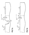
- FIG. 7 a is a schematic representation showing the length of the inner path extended in the pathlength compensation scheme, according to the present invention.
- FIG. 7 b is a schematic representation showing the outer path.
- FIG. 7 c is a schematic representation showing the top view of sheet accumulating system wherein the cut sheet on the inner path is given a head start by extending the length of the inner path.
- one way to increase the overlapped amount on the cut sheets is to give the sheet on the outer path a head start because it travels a longer distance.
- the outer cut sheet 44 is positioned ahead of the inner cut sheet 42 by a distance D before they encounter the right angle transport device 50 .
- the sheets 42 , 44 engage with the turn-over modules 52 , 54 at different times, as shown in FIGS. 4 b to 4 d .
- the turn-over modules 52 , 54 As both sheets emerge from the turn-over modules 52 , 54 , their turned-over sections will align with each other, as can be seen in FIGS. 4 c and 4 d .
- the turn-over modules 52 , 54 function as a collation device.
- the sheets 42 , 44 exit from the right-angle transport device 50 , they totally overlap with each other, as shown in FIG. 4 e .
- the term “head start” in this context simply means that the outer sheet 44 is given an advantageous starting position so that it will reach the corresponding turn-over module 54 ahead of the inner sheet 42 , although both sheets move at the same time with the same speed.
- the pathlength compensation method gives the outer cut sheet an advantageous starting position by extending the length of the inner path 112 (see FIG. 2 b for the inner path before pathlength extension). If so desired, the inner path 112 can be extended so that it is equal to the inner path 114 in length.
- the pathlength compensation scheme is illustrated in FIGS. 5 a and 5 b . Before pathlength compensation, the length of the outer path 114 is greater than the length of the extended inner path 112 by a distance D, as shown in FIG. 5 a . After pathlength compensation, the length of the inner path 112 ′ and that of the outer path 114 are substantially equal (as shown in FIG. 5 b ). As such, the outer sheet 44 reaches the turn-over module 54 before the inner sheet 42 reaches the turn-over module 52 , although they move toward the respective turn-over modules at the same time with the same speed.
- the pathlength compensation scheme is the replacement of a straight path by a curved path between two points while maintaining the original moving direction of the sheet after the sheet emerges from the curved path.
- a curved section from E to F of the path 112 ′ is used to replace a section from A to B of the path 112 in order to compensate for the additional path OM traversed by the sheet 44 and to effectively increase the pathlength from X to M.
- the extension of the inner path 112 can be realized by adding to the traveling path of the cut sheet 42 a paper-path tube 122 that deflects the cut sheet 42 from the existing horizontal paper path.
- FIG. 6 A schematic representation of the paper-path tube 122 is shown in FIG. 6 .
- the paper-path tube 122 comprises an upper paper guide 124 and a lower paper guide 126 forming a channel 128 therebetween so as to force the cut sheet 42 to go a greater distance.
- the sheet 42 is deflected by the upper paper guide 124 at the entrance point E and caused to deviate from the original path 112 at point A (See FIG. 5 c ) and enter the channel 128 . If the paper guides 124 , 126 do not reduce the speed of the cut sheet 42 , then there is no need to use an additional driving mechanism to move the cut sheet 42 through the channel 128 .
- a plurality of driving rollers 130 can be used to maintain the speed of the cut sheet 42 within the paper-path tube 122 .
- the orientation of the paper tube 122 can be upward or downward. This means that the extended inner path 112 ′ can be positioned above or below the existing horizontal inner path 112 .
- FIG. 7 a illustrates the traveling path of the inner cut sheet 42 , extended by a downward-oriented paper path, similar to the paper-path tube 122 .
- the traveling path of the outer cut sheet 44 is straight and horizontal, as shown in FIG. 7 b .
- the leading edge 142 of the inner cut sheet 42 lags behind the leading edge 144 of the outer cut sheet 44 .
- the extended pathlength 112 ′ gives the outer cut sheet 44 an advantageous starting position, similar to the situation as depicted in FIG. 4 a.
- both the inner cut sheet 42 and the outer cut sheet 44 in a 2-sheet packet can be made completely or substantially overlapped.
- the present invention simplifies the control logic of the web cutter 16 , especially when this type of 2-up cutter (for cutting two webs of material linked by a center perforation) is used for half-cutting the web.
- the period between two consecutive 2-sheet packets is 100 ms.
- the minimum time between individual half-cuts is always 100 ms, regardless of whether the sheet is on the inner or outer path. This effectively eliminates the parameter referred to as “tongue delay”, which is the additional time delay added between collations that are side-by-side on the web for an uncompensated system.
- the effective length of the paper path tube 122 can be adjusted according to the difference between the length L and the width W of the cut sheets 42 , 44 .
- the effective length of the paper path tube 122 is fixed such that there is always a slight offset between the two sheets in a 2-sheet packet while maintaining a minimum allowable gap between two consecutive packets. It can be designed that, for all specified sheet widths, a slight offset is allowed such that the inner sheet 42 is always slightly more downstream than the outer sheet 44 , or the leading edge 142 is slightly ahead of the leading edge 144 when exiting the right angle transport device for all specified sheet widths.
- the present invention has been disclosed as a pathlength compensation method in a sheet accumulating system, wherein a continuous web cutter is used to cut two webs into groups of two sheets, and the two sheets in any group move substantially side-by-side along the same direction. It should be noted, however, that the present invention is also applicable to a sheet accumulating system, wherein a continuous web cutter is used to cut three or more webs into groups of three or more sheets, and the sheets in any group move in a substantially side-by-side manner. In the case of three or more webs, only the outermost sheet would have a horizontal path, while the inner sheets would have progressively longer compensated paths.
Landscapes
- Engineering & Computer Science (AREA)
- Mechanical Engineering (AREA)
- Collation Of Sheets And Webs (AREA)
Abstract
Description
| Cutter rate | Gap | Gap |
| (thousand per hour) | (inches) | (milliseconds) |
| 25 | 4.34 | 30 |
| 27 | 2.79 | 19 |
| 30 | 0.86 | 6 |
| 36 | −2.04 | −14 |
Claims (12)
Priority Applications (1)
| Application Number | Priority Date | Filing Date | Title |
|---|---|---|---|
| US10/280,382 US6764070B2 (en) | 2002-10-25 | 2002-10-25 | Pathlength compensation method and device for high speed sheet cutters |
Applications Claiming Priority (1)
| Application Number | Priority Date | Filing Date | Title |
|---|---|---|---|
| US10/280,382 US6764070B2 (en) | 2002-10-25 | 2002-10-25 | Pathlength compensation method and device for high speed sheet cutters |
Publications (2)
| Publication Number | Publication Date |
|---|---|
| US20040080097A1 US20040080097A1 (en) | 2004-04-29 |
| US6764070B2 true US6764070B2 (en) | 2004-07-20 |
Family
ID=32106919
Family Applications (1)
| Application Number | Title | Priority Date | Filing Date |
|---|---|---|---|
| US10/280,382 Expired - Lifetime US6764070B2 (en) | 2002-10-25 | 2002-10-25 | Pathlength compensation method and device for high speed sheet cutters |
Country Status (1)
| Country | Link |
|---|---|
| US (1) | US6764070B2 (en) |
Cited By (3)
| Publication number | Priority date | Publication date | Assignee | Title |
|---|---|---|---|---|
| US20060188305A1 (en) * | 2005-02-23 | 2006-08-24 | Lexmark International, Inc. | Uniform entry of media into an alignment nip |
| US20090167505A1 (en) * | 2006-08-25 | 2009-07-02 | Brother Kogyo Kabushiki Kaisha | Operation processing apparatus |
| EP2876069A1 (en) | 2013-11-13 | 2015-05-27 | Bell and Howell, LLC | An inserting system and method for aligning a plurality of sheets |
Families Citing this family (6)
| Publication number | Priority date | Publication date | Assignee | Title |
|---|---|---|---|---|
| EP1790602A1 (en) * | 2005-11-24 | 2007-05-30 | Philip Morris Products S.A. | Apparatus for producing and transporting folded coupons |
| US7611134B2 (en) * | 2005-12-13 | 2009-11-03 | Pitney Bowes Inc. | Cutter sequencing method and apparatus |
| US20070146135A1 (en) * | 2005-12-27 | 2007-06-28 | David Boyadjieff | Assembling RFID components using webs |
| IT1396112B1 (en) * | 2009-07-15 | 2012-11-16 | C M C Srl | DEVICE FOR THE ADDRESSING OF SHEETS COMING FROM ANGULAR LINES ARRANGED TOWARDS A LINE OF EXIT |
| CN104192621B (en) * | 2014-08-21 | 2017-01-25 | 浙江欧耐斯屋面瓦业有限公司 | Splitting corner rotating device for laminated tile production |
| CN111439616A (en) * | 2020-03-23 | 2020-07-24 | 广德东威科技有限公司 | Rolling machine and cutting device |
Citations (4)
| Publication number | Priority date | Publication date | Assignee | Title |
|---|---|---|---|---|
| JPH02204237A (en) * | 1989-01-30 | 1990-08-14 | Konica Corp | Electrophotography copying machine with a plurality of paper feed sources |
| US5415385A (en) * | 1994-01-21 | 1995-05-16 | Southern Illinois Machinery Co., Incorporated | Apparatus for collating and feeding documents |
| US6443447B1 (en) * | 2000-12-29 | 2002-09-03 | Pitney Bowes Inc. | Method and device for moving cut sheets in a sheet accumulating system |
| US6659445B2 (en) * | 2001-07-16 | 2003-12-09 | Müller Martini Holding AG | Arrangement for forming a third stream of first and second streams comprised of printed products |
-
2002
- 2002-10-25 US US10/280,382 patent/US6764070B2/en not_active Expired - Lifetime
Patent Citations (4)
| Publication number | Priority date | Publication date | Assignee | Title |
|---|---|---|---|---|
| JPH02204237A (en) * | 1989-01-30 | 1990-08-14 | Konica Corp | Electrophotography copying machine with a plurality of paper feed sources |
| US5415385A (en) * | 1994-01-21 | 1995-05-16 | Southern Illinois Machinery Co., Incorporated | Apparatus for collating and feeding documents |
| US6443447B1 (en) * | 2000-12-29 | 2002-09-03 | Pitney Bowes Inc. | Method and device for moving cut sheets in a sheet accumulating system |
| US6659445B2 (en) * | 2001-07-16 | 2003-12-09 | Müller Martini Holding AG | Arrangement for forming a third stream of first and second streams comprised of printed products |
Cited By (6)
| Publication number | Priority date | Publication date | Assignee | Title |
|---|---|---|---|---|
| US20060188305A1 (en) * | 2005-02-23 | 2006-08-24 | Lexmark International, Inc. | Uniform entry of media into an alignment nip |
| US7613420B2 (en) | 2005-02-23 | 2009-11-03 | Lexmark International, Inc. | Uniform entry of media into an alignment nip |
| US20090167505A1 (en) * | 2006-08-25 | 2009-07-02 | Brother Kogyo Kabushiki Kaisha | Operation processing apparatus |
| EP2876069A1 (en) | 2013-11-13 | 2015-05-27 | Bell and Howell, LLC | An inserting system and method for aligning a plurality of sheets |
| EP2876069B1 (en) * | 2013-11-13 | 2016-09-21 | Bell and Howell, LLC | A mailpiece inserting system and method for aligning a plurality of sheets |
| US9540203B2 (en) | 2013-11-13 | 2017-01-10 | Bell And Howell, Llc | Method and system for synchronizing items using position compensation |
Also Published As
| Publication number | Publication date |
|---|---|
| US20040080097A1 (en) | 2004-04-29 |
Similar Documents
| Publication | Publication Date | Title |
|---|---|---|
| US6572520B2 (en) | Apparatus for transporting envelope blanks in an envelope making machine | |
| US3976237A (en) | Web guide systems | |
| US4919027A (en) | Sheet diverting and delivery system | |
| US6764070B2 (en) | Pathlength compensation method and device for high speed sheet cutters | |
| US8342675B2 (en) | Newspaper production system and production method for newspaper | |
| EP0315932B1 (en) | Folding machine in a rotary press | |
| CA2740834C (en) | Conveying apparatus for envelopes and related methods | |
| US5865082A (en) | Apparatus for transporting signatures | |
| US6443447B1 (en) | Method and device for moving cut sheets in a sheet accumulating system | |
| US20070203007A1 (en) | Structure of interfolding machine with adjustable cut-off | |
| US6659445B2 (en) | Arrangement for forming a third stream of first and second streams comprised of printed products | |
| US6460842B1 (en) | Device for superposing sheets of paper or the like | |
| US6302392B1 (en) | Sheet diverter for collating signatures and a method thereof | |
| JP2549207B2 (en) | Folding device | |
| JPS6212577A (en) | Method and device for folding endless band-shaped material to zigzag shape | |
| US5707054A (en) | Folding apparatus having a copy-forming auxiliary module | |
| US4969640A (en) | Sweet diverting and delivery system | |
| EP4055336B1 (en) | Production line for handling of panels | |
| US8020847B2 (en) | Multiple delivery web conversion apparatus and method of producing and delivering variable printed products | |
| US20150080199A1 (en) | Method of, and apparatus for, processing a moving, printed material web | |
| US4606534A (en) | Combined separating, bursting and sorting apparatus for a continuous web of multi-forms | |
| US5915301A (en) | Upper folder drive roll arrangement | |
| EP1798176B1 (en) | Cutter sequencing method and apparatus | |
| US10093513B2 (en) | Folding apparatus and method | |
| US20030177922A1 (en) | Symmetrical parallel duplex paper path device |
Legal Events
| Date | Code | Title | Description |
|---|---|---|---|
| AS | Assignment |
Owner name: PITNEY BOWES INC., CONNECTICUT Free format text: ASSIGNMENT OF ASSIGNORS INTEREST;ASSIGNORS:MASOTTA, JOHN R.;SKINGER, GROGORY P.;SUSSMEIER, JOHN W.;AND OTHERS;REEL/FRAME:013431/0016 Effective date: 20021023 |
|
| STCF | Information on status: patent grant |
Free format text: PATENTED CASE |
|
| FPAY | Fee payment |
Year of fee payment: 4 |
|
| FPAY | Fee payment |
Year of fee payment: 8 |
|
| FPAY | Fee payment |
Year of fee payment: 12 |
|
| AS | Assignment |
Owner name: DEUTSCHE BANK AG NEW YORK BRANCH, NEW YORK Free format text: SECURITY AGREEMENT;ASSIGNOR:DMT SOLUTIONS GLOBAL CORPORATION;REEL/FRAME:046467/0901 Effective date: 20180702 |
|
| AS | Assignment |
Owner name: DEUTSCHE BANK AG NEW YORK BRANCH, NEW YORK Free format text: TERM LOAN SECURITY AGREEMENT;ASSIGNOR:DMT SOLUTIONS GLOBAL CORPORATION;REEL/FRAME:046473/0586 Effective date: 20180702 |
|
| AS | Assignment |
Owner name: DMT SOLUTIONS GLOBAL CORPORATION, CONNECTICUT Free format text: ASSIGNMENT OF ASSIGNORS INTEREST;ASSIGNOR:PITNEY BOWES INC.;REEL/FRAME:046597/0120 Effective date: 20180627 |
|
| AS | Assignment |
Owner name: DMT SOLUTIONS GLOBAL CORPORATION, CONNECTICUT Free format text: RELEASE BY SECURED PARTY;ASSIGNOR:DEUTSCHE BANK AG NEW YORK BRANCH;REEL/FRAME:064785/0374 Effective date: 20230830 Owner name: DMT SOLUTIONS GLOBAL CORPORATION, CONNECTICUT Free format text: RELEASE BY SECURED PARTY;ASSIGNOR:DEUTSCHE BANK AG NEW YORK BRANCH;REEL/FRAME:064785/0325 Effective date: 20230830 |