US6758057B2 - Bimodal refrigeration system and method - Google Patents
Bimodal refrigeration system and method Download PDFInfo
- Publication number
- US6758057B2 US6758057B2 US10/409,351 US40935103A US6758057B2 US 6758057 B2 US6758057 B2 US 6758057B2 US 40935103 A US40935103 A US 40935103A US 6758057 B2 US6758057 B2 US 6758057B2
- Authority
- US
- United States
- Prior art keywords
- forced
- cargo
- air current
- cargo chamber
- bimodal
- Prior art date
- Legal status (The legal status is an assumption and is not a legal conclusion. Google has not performed a legal analysis and makes no representation as to the accuracy of the status listed.)
- Expired - Lifetime
Links
- 238000005057 refrigeration Methods 0.000 title claims abstract description 84
- 230000002902 bimodal effect Effects 0.000 title claims abstract description 34
- 238000000034 method Methods 0.000 title description 9
- 239000011232 storage material Substances 0.000 claims abstract description 40
- 238000001816 cooling Methods 0.000 claims description 12
- 230000007246 mechanism Effects 0.000 claims description 10
- 230000000717 retained effect Effects 0.000 claims description 4
- 239000012782 phase change material Substances 0.000 claims description 3
- 238000007599 discharging Methods 0.000 claims 2
- 239000000499 gel Substances 0.000 description 17
- 238000009413 insulation Methods 0.000 description 16
- 239000002131 composite material Substances 0.000 description 11
- RZVAJINKPMORJF-UHFFFAOYSA-N Acetaminophen Chemical compound CC(=O)NC1=CC=C(O)C=C1 RZVAJINKPMORJF-UHFFFAOYSA-N 0.000 description 10
- 229920005830 Polyurethane Foam Polymers 0.000 description 10
- 239000011496 polyurethane foam Substances 0.000 description 10
- 239000000463 material Substances 0.000 description 7
- 239000003507 refrigerant Substances 0.000 description 7
- 230000008859 change Effects 0.000 description 6
- 230000001351 cycling effect Effects 0.000 description 6
- XLYOFNOQVPJJNP-UHFFFAOYSA-N water Chemical compound O XLYOFNOQVPJJNP-UHFFFAOYSA-N 0.000 description 6
- 238000009826 distribution Methods 0.000 description 5
- 238000012546 transfer Methods 0.000 description 5
- 239000011248 coating agent Substances 0.000 description 4
- 238000000576 coating method Methods 0.000 description 4
- 238000000605 extraction Methods 0.000 description 4
- 239000002184 metal Substances 0.000 description 4
- 230000002829 reductive effect Effects 0.000 description 4
- 239000000126 substance Substances 0.000 description 4
- 238000010521 absorption reaction Methods 0.000 description 3
- 238000007710 freezing Methods 0.000 description 3
- 230000008014 freezing Effects 0.000 description 3
- 229920002635 polyurethane Polymers 0.000 description 3
- 239000004814 polyurethane Substances 0.000 description 3
- 238000012384 transportation and delivery Methods 0.000 description 3
- IJGRMHOSHXDMSA-UHFFFAOYSA-N Atomic nitrogen Chemical compound N#N IJGRMHOSHXDMSA-UHFFFAOYSA-N 0.000 description 2
- CURLTUGMZLYLDI-UHFFFAOYSA-N Carbon dioxide Chemical compound O=C=O CURLTUGMZLYLDI-UHFFFAOYSA-N 0.000 description 2
- 230000004075 alteration Effects 0.000 description 2
- 230000004888 barrier function Effects 0.000 description 2
- 230000008901 benefit Effects 0.000 description 2
- 238000009833 condensation Methods 0.000 description 2
- 230000005494 condensation Effects 0.000 description 2
- 230000006378 damage Effects 0.000 description 2
- 239000003814 drug Substances 0.000 description 2
- 230000005611 electricity Effects 0.000 description 2
- 230000001965 increasing effect Effects 0.000 description 2
- 239000007788 liquid Substances 0.000 description 2
- 238000012423 maintenance Methods 0.000 description 2
- 229920003023 plastic Polymers 0.000 description 2
- 239000004033 plastic Substances 0.000 description 2
- 230000008569 process Effects 0.000 description 2
- 230000002787 reinforcement Effects 0.000 description 2
- 239000007787 solid Substances 0.000 description 2
- 238000010257 thawing Methods 0.000 description 2
- 238000009827 uniform distribution Methods 0.000 description 2
- 239000004743 Polypropylene Substances 0.000 description 1
- 229910045601 alloy Inorganic materials 0.000 description 1
- 239000000956 alloy Substances 0.000 description 1
- 235000013405 beer Nutrition 0.000 description 1
- 230000000903 blocking effect Effects 0.000 description 1
- 238000007664 blowing Methods 0.000 description 1
- 229910002092 carbon dioxide Inorganic materials 0.000 description 1
- 239000001569 carbon dioxide Substances 0.000 description 1
- 230000015556 catabolic process Effects 0.000 description 1
- 239000000919 ceramic Substances 0.000 description 1
- 238000004891 communication Methods 0.000 description 1
- 230000002860 competitive effect Effects 0.000 description 1
- 230000003750 conditioning effect Effects 0.000 description 1
- 239000000356 contaminant Substances 0.000 description 1
- 239000013078 crystal Substances 0.000 description 1
- 235000013365 dairy product Nutrition 0.000 description 1
- 238000006731 degradation reaction Methods 0.000 description 1
- 230000001419 dependent effect Effects 0.000 description 1
- 239000002274 desiccant Substances 0.000 description 1
- 238000013461 design Methods 0.000 description 1
- 229940079593 drug Drugs 0.000 description 1
- 235000013399 edible fruits Nutrition 0.000 description 1
- 230000000694 effects Effects 0.000 description 1
- 238000005265 energy consumption Methods 0.000 description 1
- 239000012530 fluid Substances 0.000 description 1
- 239000006260 foam Substances 0.000 description 1
- 238000009432 framing Methods 0.000 description 1
- 239000000446 fuel Substances 0.000 description 1
- 239000000383 hazardous chemical Substances 0.000 description 1
- 235000015243 ice cream Nutrition 0.000 description 1
- 230000003116 impacting effect Effects 0.000 description 1
- 230000001939 inductive effect Effects 0.000 description 1
- 230000008595 infiltration Effects 0.000 description 1
- 238000001764 infiltration Methods 0.000 description 1
- 239000012774 insulation material Substances 0.000 description 1
- 235000013372 meat Nutrition 0.000 description 1
- 238000002483 medication Methods 0.000 description 1
- 238000012986 modification Methods 0.000 description 1
- 230000004048 modification Effects 0.000 description 1
- 229910052757 nitrogen Inorganic materials 0.000 description 1
- 230000009972 noncorrosive effect Effects 0.000 description 1
- 230000036961 partial effect Effects 0.000 description 1
- 229920000642 polymer Polymers 0.000 description 1
- -1 polypropylene Polymers 0.000 description 1
- 229920001155 polypropylene Polymers 0.000 description 1
- 230000005855 radiation Effects 0.000 description 1
- 238000011084 recovery Methods 0.000 description 1
- 230000009467 reduction Effects 0.000 description 1
- 230000001105 regulatory effect Effects 0.000 description 1
- 230000008439 repair process Effects 0.000 description 1
- 230000004044 response Effects 0.000 description 1
- 230000000284 resting effect Effects 0.000 description 1
- 230000035939 shock Effects 0.000 description 1
- 239000000758 substrate Substances 0.000 description 1
- 230000001360 synchronised effect Effects 0.000 description 1
- 230000003685 thermal hair damage Effects 0.000 description 1
- 231100000331 toxic Toxicity 0.000 description 1
- 230000002588 toxic effect Effects 0.000 description 1
- 235000013311 vegetables Nutrition 0.000 description 1
Images


Classifications
-
- B—PERFORMING OPERATIONS; TRANSPORTING
- B65—CONVEYING; PACKING; STORING; HANDLING THIN OR FILAMENTARY MATERIAL
- B65D—CONTAINERS FOR STORAGE OR TRANSPORT OF ARTICLES OR MATERIALS, e.g. BAGS, BARRELS, BOTTLES, BOXES, CANS, CARTONS, CRATES, DRUMS, JARS, TANKS, HOPPERS, FORWARDING CONTAINERS; ACCESSORIES, CLOSURES, OR FITTINGS THEREFOR; PACKAGING ELEMENTS; PACKAGES
- B65D88/00—Large containers
- B65D88/74—Large containers having means for heating, cooling, aerating or other conditioning of contents
- B65D88/745—Large containers having means for heating, cooling, aerating or other conditioning of contents blowing or injecting heating, cooling or other conditioning fluid inside the container
-
- B—PERFORMING OPERATIONS; TRANSPORTING
- B60—VEHICLES IN GENERAL
- B60H—ARRANGEMENTS OF HEATING, COOLING, VENTILATING OR OTHER AIR-TREATING DEVICES SPECIALLY ADAPTED FOR PASSENGER OR GOODS SPACES OF VEHICLES
- B60H1/00—Heating, cooling or ventilating [HVAC] devices
- B60H1/00007—Combined heating, ventilating, or cooling devices
- B60H1/00014—Combined heating, ventilating, or cooling devices for load cargos on load transporting vehicles
-
- B—PERFORMING OPERATIONS; TRANSPORTING
- B60—VEHICLES IN GENERAL
- B60H—ARRANGEMENTS OF HEATING, COOLING, VENTILATING OR OTHER AIR-TREATING DEVICES SPECIALLY ADAPTED FOR PASSENGER OR GOODS SPACES OF VEHICLES
- B60H1/00—Heating, cooling or ventilating [HVAC] devices
- B60H1/00492—Heating, cooling or ventilating [HVAC] devices comprising regenerative heating or cooling means, e.g. heat accumulators
- B60H1/005—Regenerative cooling means, e.g. cold accumulators
-
- B—PERFORMING OPERATIONS; TRANSPORTING
- B60—VEHICLES IN GENERAL
- B60P—VEHICLES ADAPTED FOR LOAD TRANSPORTATION OR TO TRANSPORT, TO CARRY, OR TO COMPRISE SPECIAL LOADS OR OBJECTS
- B60P3/00—Vehicles adapted to transport, to carry or to comprise special loads or objects
- B60P3/20—Refrigerated goods vehicles
-
- F—MECHANICAL ENGINEERING; LIGHTING; HEATING; WEAPONS; BLASTING
- F25—REFRIGERATION OR COOLING; COMBINED HEATING AND REFRIGERATION SYSTEMS; HEAT PUMP SYSTEMS; MANUFACTURE OR STORAGE OF ICE; LIQUEFACTION SOLIDIFICATION OF GASES
- F25D—REFRIGERATORS; COLD ROOMS; ICE-BOXES; COOLING OR FREEZING APPARATUS NOT OTHERWISE PROVIDED FOR
- F25D16/00—Devices using a combination of a cooling mode associated with refrigerating machinery with a cooling mode not associated with refrigerating machinery
-
- F—MECHANICAL ENGINEERING; LIGHTING; HEATING; WEAPONS; BLASTING
- F25—REFRIGERATION OR COOLING; COMBINED HEATING AND REFRIGERATION SYSTEMS; HEAT PUMP SYSTEMS; MANUFACTURE OR STORAGE OF ICE; LIQUEFACTION SOLIDIFICATION OF GASES
- F25D—REFRIGERATORS; COLD ROOMS; ICE-BOXES; COOLING OR FREEZING APPARATUS NOT OTHERWISE PROVIDED FOR
- F25D17/00—Arrangements for circulating cooling fluids; Arrangements for circulating gas, e.g. air, within refrigerated spaces
- F25D17/005—Arrangements for circulating cooling fluids; Arrangements for circulating gas, e.g. air, within refrigerated spaces in cold rooms
-
- F—MECHANICAL ENGINEERING; LIGHTING; HEATING; WEAPONS; BLASTING
- F25—REFRIGERATION OR COOLING; COMBINED HEATING AND REFRIGERATION SYSTEMS; HEAT PUMP SYSTEMS; MANUFACTURE OR STORAGE OF ICE; LIQUEFACTION SOLIDIFICATION OF GASES
- F25D—REFRIGERATORS; COLD ROOMS; ICE-BOXES; COOLING OR FREEZING APPARATUS NOT OTHERWISE PROVIDED FOR
- F25D2201/00—Insulation
- F25D2201/10—Insulation with respect to heat
- F25D2201/12—Insulation with respect to heat using an insulating packing material
- F25D2201/126—Insulation with respect to heat using an insulating packing material of cellular type
-
- F—MECHANICAL ENGINEERING; LIGHTING; HEATING; WEAPONS; BLASTING
- F25—REFRIGERATION OR COOLING; COMBINED HEATING AND REFRIGERATION SYSTEMS; HEAT PUMP SYSTEMS; MANUFACTURE OR STORAGE OF ICE; LIQUEFACTION SOLIDIFICATION OF GASES
- F25D—REFRIGERATORS; COLD ROOMS; ICE-BOXES; COOLING OR FREEZING APPARATUS NOT OTHERWISE PROVIDED FOR
- F25D2201/00—Insulation
- F25D2201/10—Insulation with respect to heat
- F25D2201/14—Insulation with respect to heat using subatmospheric pressure
-
- F—MECHANICAL ENGINEERING; LIGHTING; HEATING; WEAPONS; BLASTING
- F25—REFRIGERATION OR COOLING; COMBINED HEATING AND REFRIGERATION SYSTEMS; HEAT PUMP SYSTEMS; MANUFACTURE OR STORAGE OF ICE; LIQUEFACTION SOLIDIFICATION OF GASES
- F25D—REFRIGERATORS; COLD ROOMS; ICE-BOXES; COOLING OR FREEZING APPARATUS NOT OTHERWISE PROVIDED FOR
- F25D2303/00—Details of devices using other cold materials; Details of devices using cold-storage bodies
- F25D2303/08—Devices using cold storage material, i.e. ice or other freezable liquid
- F25D2303/085—Compositions of cold storage materials
Definitions
- the present invention relates generally to refrigeration systems, and in particular to refrigerated containers or enclosures that employ mechanical refrigeration systems to maintain goods at a desired temperature during transport or storage. More particularly, the present invention relates to an improved system and method employing endothermic storage material in conjunction with forced air mechanical refrigeration to provide a more efficient refrigerated storage containment unit.
- Transportable cargo containers are well known in the shipping industry and typically comprise generally rectangular containers adapted to be placed onto wheeled chassis, railroad cars, ocean-going ships, etc., or are manufactured as an integral wheeled trailer or railroad car. Many goods and foodstuffs require refrigeration during transport to prevent spoilage or degradation, and it is well known to provide cargo containers with cooling and thermal insulation systems in order to maintain the cargo within a desired temperature range.
- Polyurethane foam is typically installed as solid sheets or as an injected foam within the containment walls of refrigerated cargo containers to form a thermal insulation barrier against outside ambient temperatures.
- the selection of a heat extraction system for conventional refrigerated cargo containers is made in accordance with temperature control and thermal efficiency characteristics that are best suited for a particular cargo type, and furthermore, in accordance with transport and delivery logistics.
- cooling is often provided by blowing or injecting crushed ice or other endothermic substances, including toxic or otherwise hazardous chemicals such as liquid nitrogen or frozen carbon dioxide crystals, into the cargo container.
- closed door cooling systems are well-suited for relatively uninterrupted end-to-end long distance deliveries, and are highly efficient in terms of electricity and fuel consumption required to maintain the cargo below a given temperature.
- the sharp thermal gradients resulting from injecting the refrigerant directly into the cargo space in a solid, liquid or gaseous state results in damage to sensitive cargos such as produce and refrigerated medications.
- the direct contact between the refrigerant and moisture-laden cargo results in excessive condensation of water vapor which freezes around the refrigerant, thus forming ice sheets that pose convenience and safety problems when accessing the cargo container, and also significantly reduce the thermal exchange efficiency between the refrigerant and the cargo chamber.
- the need to maintain a controlled, low humidity atmosphere within the cargo chamber makes injected refrigerant techniques unsuitable for so-called “open-door” transport in which refrigerated or frozen goods are delivered from a centralized source such as a warehouse to several dispersed retail destinations.
- Mechanical refrigeration systems used for transport employ a conventional evaporator/condenser thermal exchange mechanism that operates in accordance with many of the same refrigeration principles used in household refrigerators and freezers.
- the mechanical refrigeration system is typically attached onto one end of a refrigerated transport container, commonly referred to in the art as a “reefer,” and includes a blower to produce a forced-air cooling effect within the container, inducing a convective mode of heat transfer required for quickly restoring and maintaining the prescribed cargo temperature in an open door transport context.
- the air exhaust requirements of refrigerator condenser fans restricts the loading and placement of mechanically refrigerated containers to above-deck locations where the warm condenser exhaust is freely released into the open atmosphere without negatively impacting other nearby refrigerated containers.
- This locatability restriction naturally results in a competitive scarcity of available above-deck storage space, significantly increasing shipping costs for reefers.
- the continuous cycling of mechanical refrigeration systems results in significant maintenance costs incurred in repairing and replacing worn or depleted refrigeration system components and related power generating components.
- a bimodal refrigeration system is disclosed herein.
- the present invention includes a refrigerated container having an enclosed cargo chamber for storing refrigerated goods and a mechanical refrigeration unit that produces a chilled forced-air circulation within the cargo chamber.
- the cargo chamber is designed to guide the forced-air in a specified discharge and return path.
- a row of thermal storage ducts for retaining endothermic storage material are disposed within the cargo chamber.
- the thermal storage ducts are longitudinally disposed in parallel with the air flow direction of the specified forced-air discharge and return path to enable maximum convective thermal exchange between the forced-air current and the endothermic storage material without obstructing the specified forced-air discharge and return path.
- FIG. 1 is a perspective view depicting an improved bimodal refrigeration system in accordance with a preferred embodiment of the present invention
- FIG. 2 illustrates a side profile view of a refrigerated container cargo chamber as designed and implemented within the bimodal refrigeration system of the present is invention
- FIG. 3 is a partial cross section profile view depicting the mutual disposition of multiple thermal storage ducts as arranged on the ceiling of a refrigerated container in accordance with a preferred embodiment of the present invention
- FIG. 4 is a more detailed front or rear cross section profile view of a thermal storage duct as deployed within a refrigerated container in accordance with the present invention
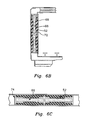
- FIGS. 5A-5C illustrate various cross section views of an improved thermal insulation apparatus in accordance with one embodiment of the present invention.
- FIGS. 6A-6C depict various cross section views of an improved thermal insulation apparatus in accordance with an alternate embodiment of the present invention.
- the bimodal refrigeration system of the present invention employs an endothermic storage material within a refrigerated container in a manner that leverages the features of conventional mechanical refrigeration units, particularly mechanical refrigeration units employing forced-air chilling.
- the bimodal refrigeration system advantageously employs a “passive” heat exchange mode in the form of an endothermic storage apparatus compatibly deployed within a refrigerated container.
- a “bimodal” refrigeration system refers to a heat extraction/absorption system employing a passive heat exchange mechanism in the form of an endothermic storage material in conjunction with an active heat exchange mechanism in the form of a forced-air mechanical refrigeration unit.
- the bimodal refrigeration system efficiently addresses problems and costs associated with conventional refrigerated cargo systems including uneven cooling of temperature sensitive cargo and ice buildup resulting from excessive condensation within the cargo chamber. Furthermore, the bimodal cooling mechanism of the present invention reduces the required active operating time and excessive cycling of the resident mechanical refrigeration unit. Such reduction of active cycling of the mechanical refrigeration unit consequently reduces the overall energy supply requirements such as provided by diesel generators and the like, and also reduces repair and maintenance costs of the mechanical refrigeration unit.
- the present invention is implemented within a refrigerated container having a conventional forced-air mechanical refrigeration unit that produces and directs chilled air into the interior of the container or room as required to lower and then maintain the temperature within the container or room at or below a predetermined temperature.
- Thermal storage ducts having a number of air flow apertures are fixedly coupled to the ceiling of the refrigerated container, wherein a thermally chargeable material having a suitable phase change or stasis temperature, and preferably contained within discrete sealed packets, is evenly distributed in a suspended manner above the cargo chamber interior of the refrigerated container.
- the chilled, forced-air current is discharged into the interior cargo chamber of a refrigerated container.
- the cargo chamber includes air flow guide means for directing the chilled, forced-air current in a specified discharge and return path from a forced-air outtake of the mechanical refrigeration unit around the top, backside, and bottom of a refrigerated cargo load and back to a return port.
- the specified discharge and return path is composed of one or more parallel air flow loops around the top, backside, and bottom sides of a cargo load resting on the floor of the cargo chamber.
- a row of two or more thermal storage ducts are disposed in parallel rows along the longitudinal extent of the refrigerated container's ceiling in parallel with the direction of the specified discharge and return forced airflow path.
- a substantial volume of the chilled, forced airflow is funneled between the multiple open channels between adjacent storage ducts to promote maximum convective thermal exchange between the forced-air current and a chargeable endothermic storage material retained within the thermal storage ducts.
- the parallel, longitudinally disposed storage duct rows enable a comprehensive and uniform distribution of endothermic storage material over the cargo load to maintain the thermal integrity of the load without unduly obstructing the discharge or return air flow path.
- the chilled airflow from the mechanical refrigeration unit is used to bring the endothermic storage material to the required phase change or stasis temperature.
- passive mode enabled when the endothermic storage material has reached its stasis temperature, the mechanical refrigeration system deactivates and the activated storage material serves as a suspended, non-mechanically driven heat sink for a passive thermal convection mechanism wherein a passive convective air current resulting from so-called natural thermal circulation is baffled through the duct apertures to promote an even thermal distribution throughout the cargo chamber.
- the presence of this passive heat sink and natural convective flow maintains the reduced internal temperature of the container or room for an extended period of time.
- the predictability of the passive mode periods enables thermal recharge cycling of the mechanical refrigeration unit to be synchronized with “off-peak” hours when the cost of electricity is lower than during peak demand hours.
- the system as described is also useful in reducing or precluding excessive moisture within the container or room, which can be a significant problem.
- excess moisture during the pre-cooling loading cycle results in the build-up of ice on the cooling coils, requiring the unit to be reversed in a defrost cycle wherein the coils are defrosted.
- This need for defrosting may occur multiple times during the chilling process, resulting in a thermal and energy inefficient process.
- the refrigerated container is provided with additional insulating elements to reduce outside heat infiltration into the interior of the container or room from UV, radiant, heat and convection.
- the exterior of the container is preferably coated with a thermal reflective coating to reduce heat absorption from UV radiation.
- panels with high insulation values are disposed on the interior of the container to achieve optimum thermal storage efficiency.
- FIG. 1 illustrates a refrigerated container 10 which is a generally rectangular structure having a set of cargo doors 11 on a backside end and a mechanical refrigeration unit 20 mounted on the frontside end, and may be structurally adapted to be mountable onto a wheeled chassis for intermodal truck transport.
- refrigerated container 10 includes insulated walls, floors and ceilings.
- a thermostatically controlled mechanical refrigeration unit 20 that monitors and regulates the temperature within an interior cargo chamber 8 and the refrigerated cargo stored therein.
- mechanical refrigeration unit 20 employs a conventional evaporator/condenser system that produces chilled air and furthermore includes blowers or fans (not depicted) to forcefully discharge the chilled air into an interior cargo chamber 8 to achieve rapid temperature control or recovery.
- blowers or fans not depicted
- Such mechanical refrigeration systems are well known and widely utilized to store and maintain goods in transit that at reduced temperatures, such as between 32 to 55 degrees F. for fruit, vegetables, beer, dairy products, pharmaceuticals, and the like, or between minus 20 and 32 degrees F. for frozen meat, ice cream, and the like.
- the other thermal control modality employed by refrigerated container 10 is achieved by compatibly deploying an endothermic storage material, such as an endothermic gel material or a phase change material, in conjunction with the cycling, forced-air heat extraction mechanism to acheive substantially increased thermal extraction and absorption capacity, a more even thermal gradient distribution, and a reduced cycling of mechanical refrigeration unit 20 .
- an endothermic storage material such as an endothermic gel material or a phase change material
- the endothermic storage material is advantageously deployed within each of a row of thermal storage ducts 30 , which as depicted in FIG. 1, are longitudinally extended along the interior ceiling 12 of cargo chamber 8 .
- thermal storage ducts 30 extend longitudinally in a straight, parallel path from the front to the back end of cargo chamber 8 , but other arrangements are possible.
- thermal storage ducts 30 extend longitudinally in a slightly curved or slanted manner that facilitates smooth and unobstructed air flow between the front and rear ceiling of cargo chamber 8 .
- thermal storage ducts 30 may also be mounted on the walls or the floor of refrigerated container 10 .
- Thermal storage ducts 30 may be constructed of any suitable material, such as a sheet metal or plastic, but are preferably made of a suitably heat conductive and non-corrosive metal or alloys.
- Thermal storage ducts 30 are in fluid communication with the discharge or fan unit or units (not depicted) of mechanical refrigeration unit 20 , such that a primary forced-air flowpath within cargo chamber 8 is directed into rows of longitudinal channels 18 formed between the storage duct rows.
- thermal storage ducts 30 are provided with a number of flow apertures 31 through which a sub-volume of the forced-air current flowing guided by channels 18 passes into the interior of thermal storage ducts 30 .
- Flow apertures 31 may consist of holes or slots or any other suitable aperture shape or contour suitable for enabling air flow from cargo chamber 8 to enter the storage ducts.
- FIGS. 2 and 3 depict a side profile view and a lateral cross section view, respectively, of the interior of refrigerated container 10 illustrating the means for directing the forced airflow and the manner in which the bimodal refrigeration system of the present invention leverages these means to provide a maximally efficient thermal transfer mechanism between the mechanical refrigeration unit and the endothermic storage material while not obstructing the necessary discharge and return airflow path.
- cargo doors 11 are closed to form an enclosed, substantially rectangular cargo chamber interior in which a refrigerated cargo 5 has been loaded.
- refrigerated container 10 employs a so-called “bottom flow” forced-air circulation system in which a chilled forced-air current is blown from mechanical refrigeration unit 20 from a discharge vent or port 14 at the front, lower side of the enclosed cargo chamber.
- the forced-air current flows into a set of floor channels 4 (see FIG. 1) formed between T-rails 2 on the floor of the cargo chamber, from which the air current is guided toward the backside cargo chamber wall comprising closed cargo doors 11 .
- the forced airflow current flows upward to the cargo chamber ceiling 12 , and from there is guided between refrigerated cargo 5 and ceiling 12 in a return flow path to a return vent or port 16 on the frontside wall of the cargo chamber.
- top flow circulation system wherein the flow path is reversed from that shown in FIG. 2 may also be employed by the bimodal refrigeration system without departing from the spirit or scope of the present invention.
- the modifications necessary to implement the bimodal refrigeration system as described herein with a top-flow circulation system will be readily apparent to those skilled in the art.
- refrigerated container 10 is loaded with refrigerated cargo 5 to be stored and transported, cargo doors 11 are closed, and mechanical refrigeration unit 20 is activated to extract heat and drive the temperature within refrigerated container 10 to the prescribed storage temperature or thermostatically regulated temperature range.
- a substantial portion of the forced-air current actuated by mechanical refrigeration unit 20 is guided in the aforementioned manner underneath and behind refrigerated cargo 5 and returns to a common return path over cargo 5 along cargo chamber ceiling 12 .
- the row of thermal storage ducts 30 are longitudinally disposed in a downwardly extending manner from cargo chamber ceiling 12 to form multiple, substantially unobstructed airflow channels 18 through which the forced-air current flows in its return path to return port 16 .
- thermal storage ducts 30 shown in FIGS. 2 and 3 enables a comprehensive and even distribution of the endothermic storage material over substantially the entire ceiling area without blocking or disrupting the return airflow path, and furthermore provides a maximum convective thermal transfer surface area between the return airflow current and the exposed surface areas of thermal storage ducts 30 .
- the unobstructed airflow path provided by channels 18 permits thermal storage ducts 30 to be extended downward to a level even with or above a maximum load height limit 25 , which specifies the maximum level at which refrigerated cargo 5 can be stacked without obstructing the return air flow path.
- the bimodal refrigeration system of the present invention enables maximum loading of the cargo chamber as limited by specified height limit 25 without obstructing the return airflow path.
- the chilled, forced-air current actuated by mechanical refrigeration unit 20 is guided between thermal storage ducts 30 and through apertures 31 enabling conductive and/or convective thermal transfer between the air current and an endothermic storage material 44 retained within thermal storage ducts 30 .
- Mechanical refrigeration unit 20 operates in its active chill mode until the prescribed cargo chamber temperature is achieved and thereafter is cycled on and off either manually or by automated temperature regulation means such as a thermostat, wherein the prescribed temperature corresponds approximately to the phase change or stasis temperature of endothermic storage material 44 .
- mechanical refrigeration unit 20 is switched off manually or automatically in response to either the lapse of a predetermined “pull-down” period or as determined by an automatic temperature sensing and regulation device.
- endothermic storage material 44 has been thermally charged, as by reaching its stasis or phase change temperature, the endothermic (i.e. heat absorbing) characteristics of the storage material significantly extends the period of time over which the internal temperature of the cargo chamber 8 will remain at or below the predetermined maximum temperature without having to reactivate mechanical refrigeration unit 20 .
- the particular endothermic storage material chosen is dependent on the desired temperature to be maintained within refrigerated container 10 .
- an endothermic gel that reaches stasis at approximately minus 10 degrees F. is suitable for use in circumstances where the goods are to be maintained at or below freezing.
- gels having a higher stasis temperature will be utilized.
- refrigerated container 10 is pre-chilled to bring endothermic storage material 44 to stasis prior to loading refrigerated cargo 5 .
- the presence of excessive moisture is a major problem in that the moisture collects and freezes on the cooling coils of the mechanical refrigeration units 20 .
- refrigeration unit 20 must be reversed in a defrost cycle to melt the moisture from the coils. This defrosting cycle may occur multiple times in conventional systems, thus reducing the efficiency of the system.
- this coil freezing problem is obviated.
- the comprehensive, uniform distribution of endothermic storage material 44 across cargo chamber ceiling 12 reduces localized temperature variations within the cargo chamber.
- localized temperature variations within the cargo chamber result from orientation of the container to the sun, distribution of the goods within the container, and location of the goods relative to the chilled air ingress.
- the disposition of endothermic storage material 44 within thermal storage ducts 30 as described facilitates a passive, natural convection mode wherein temperature gradients within refrigerated container 10 are significantly reduced.
- FIG. 4 there is illustrated a more detailed lateral cross-sectional view of a thermal storage duct 30 as deployed within refrigerated container 10 in accordance with the present invention.
- one or more gel packets 40 containing an endothermic storage material are disposed within thermal storage ducts 30 .
- Gel packets 40 are be brought to stasis by maintaining the gel at a specified stasis temperature for sufficient period, typically several hours. Once activated or charged, the gel material within gel packets 40 remains active (i.e. in a phase change or stasis condition) for an extended period of time.
- Gel packets 40 are brought to stasis by the chilled air from mechanical refrigeration unit 20 , the chilled air passing into flow apertures 31 and over and around gel packets 40 prior to being directed back out through flow apertures 31 into the interior of refrigerated container 10 and onto refrigerated cargo 5 . This insures that gel packets 40 reach stasis within the shortest possible time.
- suitable gel packets 40 are the polypropylene derivative gels including Polyfoam U-TEK Model 420 gel packets, which attain stasis at minus 10 degrees F., Midland Chemical Polar Packs, and gel packets produced by Cryopak Industries of Canada, which have similar stasis levels.
- refrigerated container 10 is preferably includes an external reflective coating 50 having high UV reflective characteristics, typically a ceramic or polymer coating, such as a coating manufactured by ProTek-USA.
- a key design feature of any refrigerated container is the structure and insulation materials utilized in the outer containment walls.
- the insulation presently utilized in the containment walls of refrigerated containers is a rigid polyurethane foam composite formed by injecting a self-expanding and self-curing, relatively high-density polyurethane foam into the interior cavity 28 (see FIGS. 3 and 4) between inner and outer metallic liners 26 .
- sandwich composite polyurethane insulation provides thermal insulation to the inner cargo chamber as well as providing the structural adhesion between the outer and inner wall panels required to form a substantially rigid and robust composite suitable for mobile transport applications.
- FIGS. 5A-5C there are illustrated a cut-away and two cross section views of an improved thermal insulation apparatus that may be utilized to insulate a refrigerated container in accordance with one embodiment of the present invention.
- FIG. 5A is a cut-away view depicting multiple composite insulation panels 56 incorporated within a refrigerated container wall.
- each of composite insulation panels 56 comprises inner and outer metal liners 26 forming a cavity in which a vacuum insulated panel (VIP) 58 is integrally incorporated within a rigid polyurethane foam substrate 52 .
- VIP vacuum insulated panel
- VIPs are those produced by Dow Chemical made with Instill AF, which encloses a barrier material Advantek 7400 and a desiccant supplied by Advantek, Inc.
- VIPs have characteristically high thermal resistance factors (R factors) and are thus significantly more effective in reducing thermal losses than polyurethane foam which has a much lower R factor.
- R factors thermal resistance factors
- VIPs due to poor inherent structural support and vulnerability to thermal damage, VIPs have not been utilized for exterior wall insulation in conventional transport refrigerated containers.
- the integral deployment of VIP 58 with the polyurethane foam 52 is achieved by initially bracing the cross member VIP 58 (see FIG. 5C) within the cavity bounded by metal liners 26 and a pair of stringers 62 .
- the cross member bracing depicted in FIG. 5C provides sufficient structural support such that the pre-cured polyurethane can be injected into the cavity without buckling VIP 58 .
- composite panels 56 exhibit the superior thermal insulation characteristics of VIPs 58 in concert with the structural reinforcement and additional insulation performance provided by the injected polyurethane foam 52 .
- FIGS. 6A-6C illustrate an alternate technique for incorporating VIPs within a polyurethane composite container wall.
- a cut-away view of a refrigerated container wall 70 is depicted as comprising a grid of composite panels 75 , which similar to composite panels 56 , comprise a polyurethane foam 52 integrally molded around VIPs 66 .
- VIPs 66 are fixedly held in a grid pattern by a frame 65 prior to injecting the polyurethane foam 52 into the wall cavity.
- Frame 65 is preferably constructed of a heat resistant plastic or any other suitable lightweight framing material that is sufficiently heat resistant. As shown in FIGS.
- frame 65 preferably includes a series of U-shaped frame channels 68 and H-shaped frame channels 72 .
- composite panels 75 exhibit the superior thermal insulation characteristics of VIPs 58 in concert with the structural reinforcement and additional insulation performance provided by the injected polyurethane foam 52 .
Landscapes
- Engineering & Computer Science (AREA)
- Mechanical Engineering (AREA)
- Physics & Mathematics (AREA)
- Thermal Sciences (AREA)
- Chemical & Material Sciences (AREA)
- Combustion & Propulsion (AREA)
- General Engineering & Computer Science (AREA)
- Health & Medical Sciences (AREA)
- Public Health (AREA)
- Transportation (AREA)
- Devices That Are Associated With Refrigeration Equipment (AREA)
Abstract
Description
Claims (33)
Priority Applications (1)
| Application Number | Priority Date | Filing Date | Title |
|---|---|---|---|
| US10/409,351 US6758057B2 (en) | 2002-07-30 | 2003-04-08 | Bimodal refrigeration system and method |
Applications Claiming Priority (2)
| Application Number | Priority Date | Filing Date | Title |
|---|---|---|---|
| US39952502P | 2002-07-30 | 2002-07-30 | |
| US10/409,351 US6758057B2 (en) | 2002-07-30 | 2003-04-08 | Bimodal refrigeration system and method |
Publications (2)
| Publication Number | Publication Date |
|---|---|
| US20040020236A1 US20040020236A1 (en) | 2004-02-05 |
| US6758057B2 true US6758057B2 (en) | 2004-07-06 |
Family
ID=31191274
Family Applications (1)
| Application Number | Title | Priority Date | Filing Date |
|---|---|---|---|
| US10/409,351 Expired - Lifetime US6758057B2 (en) | 2002-07-30 | 2003-04-08 | Bimodal refrigeration system and method |
Country Status (1)
| Country | Link |
|---|---|
| US (1) | US6758057B2 (en) |
Cited By (25)
| Publication number | Priority date | Publication date | Assignee | Title |
|---|---|---|---|---|
| US20060064993A1 (en) * | 2004-09-29 | 2006-03-30 | David Tofflemire | Temperature controlled air cargo container transport dolly |
| US20060080897A1 (en) * | 2004-10-20 | 2006-04-20 | O'neal James A | Modular structure resistant to forced entry and ballistic penetration |
| US20060277847A1 (en) * | 2005-06-09 | 2006-12-14 | Manitowoc Foodservice Companies, Inc. | High-strength composite floor |
| US20080174147A1 (en) * | 2007-01-24 | 2008-07-24 | Martin Marietta Materials, Inc. | Insulated Composite Body Panel Structure for a Refrigerated Truck Body |
| US20090013712A1 (en) * | 2007-07-11 | 2009-01-15 | Robert William Norris | Refrigerated trailer and method for same |
| US20090183514A1 (en) * | 2008-01-22 | 2009-07-23 | Holmes George A | Refrigerated Container for Super Frozen Temperatures |
| US20100300133A1 (en) * | 2007-12-04 | 2010-12-02 | Maersk Container Industri A/S | Container with air guide |
| US20110283719A1 (en) * | 2009-02-09 | 2011-11-24 | Carrier Corporation | Temperature distribution improvement in refrigerated container |
| NL2009183C2 (en) * | 2012-07-13 | 2014-01-14 | Opdam Man B V H | A transport vehicle with a climate-control system. |
| US20150013369A1 (en) * | 2013-07-12 | 2015-01-15 | Innovation Thru Energy Co., Ltd | Cold-charging type truck box/cargo container and temperature-keeping box |
| US9233791B2 (en) | 2009-06-19 | 2016-01-12 | Carrier Corporation | Temperature-controlled cargo container with air distribution |
| US9821700B2 (en) | 2014-05-02 | 2017-11-21 | Thermo King Corporation | Integrated charging unit for passive refrigeration system |
| US9828164B2 (en) | 2014-05-22 | 2017-11-28 | Fontaine Engineered Products, Inc. | Intermodal container and method of constructing same |
| CN109844427A (en) * | 2016-10-10 | 2019-06-04 | 开利公司 | The method for stacking refrigeration seavan |
| US10597163B2 (en) * | 2018-02-09 | 2020-03-24 | Reflect Scientific Inc. | Air freight temperature controlled device using liquid nitrogen |
| US10598395B2 (en) | 2018-05-15 | 2020-03-24 | Emerson Climate Technologies, Inc. | Climate-control system with ground loop |
| NL2026474A (en) * | 2020-09-15 | 2021-01-26 | Univ Zhejiang | An assembled energy-saving phase transition cold storage and insulation carriage |
| US11149971B2 (en) | 2018-02-23 | 2021-10-19 | Emerson Climate Technologies, Inc. | Climate-control system with thermal storage device |
| US11346583B2 (en) | 2018-06-27 | 2022-05-31 | Emerson Climate Technologies, Inc. | Climate-control system having vapor-injection compressors |
| US11585608B2 (en) | 2018-02-05 | 2023-02-21 | Emerson Climate Technologies, Inc. | Climate-control system having thermal storage tank |
| US20230074422A1 (en) * | 2021-09-03 | 2023-03-09 | Viking Cold Solutions, Inc. | Systems and methods using thermal energy storage |
| US11851270B2 (en) | 2017-10-10 | 2023-12-26 | Advanced Composite Structures, Llc | Latch for air cargo container doors |
| US20240066942A1 (en) * | 2022-08-24 | 2024-02-29 | Caleb Arthur Sommers | System for transporting perishable goods utilizing phase change materials and waste heat |
| US11981498B2 (en) | 2019-06-28 | 2024-05-14 | Advanced Composite Structures, Llc | Thermally insulated air cargo container |
| US12091239B2 (en) | 2021-11-11 | 2024-09-17 | Advanced Composite Structures, Llc | Formed structural panel with open core |
Families Citing this family (32)
| Publication number | Priority date | Publication date | Assignee | Title |
|---|---|---|---|---|
| WO2004071885A2 (en) * | 2003-02-13 | 2004-08-26 | Martin Marietta Materials, Inc. | Insulated cargo containers |
| US7540159B2 (en) * | 2003-11-26 | 2009-06-02 | Ge Medical Systems, Inc | Superconducting magnet transport method and system |
| US20050194381A1 (en) * | 2004-03-05 | 2005-09-08 | Martin Marietta Materials, Inc. | Insulated cargo containers |
| US7587984B2 (en) * | 2004-03-05 | 2009-09-15 | Martin Marietta Materials, Inc. | Insulated cargo containers |
| US7434520B2 (en) * | 2004-04-12 | 2008-10-14 | Martin Marietta Materials, Inc. | Insulated cargo container doors |
| US7353960B2 (en) * | 2004-10-05 | 2008-04-08 | Martin Marietta Materials, Inc. | Cargo container with insulated floor |
| US20060108361A1 (en) * | 2004-10-08 | 2006-05-25 | Seiter Joseph A | Insulated cargo container doors |
| US9829898B2 (en) * | 2005-08-17 | 2017-11-28 | Jorge Saenz | Controlling cargo parameters in a microenvironment of a reefer during transit |
| BRMU8602648U (en) * | 2006-11-21 | 2008-07-08 | Eduardo Castello Branco Doria | hybrid cooling system for conveying forced air with eutectic plate |
| US20080146137A1 (en) * | 2006-12-18 | 2008-06-19 | Mark Anthony Mosunic | Multi Purpose Refrigerated Box Hold and Container Cargo Carrier with One or More Cargo Holds |
| US10442615B2 (en) * | 2008-05-28 | 2019-10-15 | Blueye, Llc | Method and transportation container for protecting temperature sensitive products |
| CA2836522A1 (en) * | 2011-05-26 | 2012-11-29 | Viking Cold Solutions, Inc. | Cold storage rack system with overhead pcm support |
| US20150040598A1 (en) * | 2011-12-19 | 2015-02-12 | Carrier Corporation | Transport Refrigeration System With Regenerative Elements |
| SG11201408248UA (en) | 2012-06-11 | 2015-02-27 | Carrier Corp | Refrigerated cargo container, method for cooling a cargo, method for heating a cargo |
| NL2010011C2 (en) * | 2012-12-19 | 2014-06-23 | Lijssel Holding B V Van | TRUCK TRAILER. |
| US9272475B2 (en) * | 2013-06-03 | 2016-03-01 | Sonoco Development, Inc. | Thermally insulated VIP sandwich shipper and method of making same |
| FR3013277B1 (en) * | 2013-11-18 | 2017-06-02 | Lamberet | ISOTHERMAL BOX FOR REFRIGERATING VEHICLE |
| JP2015161439A (en) * | 2014-02-27 | 2015-09-07 | 平出デンソー部株式会社 | Box type loading space for refrigerator truck |
| CN104019623A (en) * | 2014-06-07 | 2014-09-03 | 太仓京和机电有限公司 | Wine cabinet with assisting refrigerating system |
| CN104787435B (en) * | 2015-04-30 | 2016-03-02 | 中国石油大学(华东) | The anti-pollution harmful influence platform of autonomous type |
| CN208720605U (en) * | 2015-10-09 | 2019-04-09 | Ite株式会社 | System for maintaining refrigerated storage temperature in cold-storage apparatus |
| US20170321912A1 (en) * | 2016-05-06 | 2017-11-09 | Viking Cold Solutions, Inc. | Forced air thermal energy storage system |
| US10330378B2 (en) * | 2017-09-19 | 2019-06-25 | Reflect Scientific Inc. | Freezer with remote management |
| US10047978B1 (en) * | 2017-09-19 | 2018-08-14 | Reflect Scientific Inc. | ULT freezer with heater |
| GB2585679B (en) * | 2019-07-10 | 2024-04-10 | Maersk Line As | Power control for a container vessel |
| GB2585680B (en) * | 2019-07-10 | 2021-08-04 | Maersk Line As | Reefer power control |
| US11035603B1 (en) * | 2020-02-15 | 2021-06-15 | Reflect Scientific Inc. | Active/passive thermal control system utilizing liquid nitrogen |
| CN111498367B (en) * | 2020-03-19 | 2022-04-29 | 徐州工程学院 | Shelves for meat products refrigerated trucks |
| WO2022187699A1 (en) * | 2021-03-04 | 2022-09-09 | Cold Chain Technologies, Llc | Shipping system for storing and/or transporting temperature-sensitive materials |
| CN113650972B (en) * | 2021-08-31 | 2022-08-12 | 郑州轻工业大学 | A self-coordinated refrigerated container and its control method |
| CN118124993B (en) * | 2024-05-07 | 2024-07-23 | 山东睿展海洋生物科技有限公司 | Dampproofing transportation storage device of marine organism fodder |
| FI20245706A1 (en) * | 2024-05-31 | 2025-12-01 | Jaspi Holding L L C Fz | Method in a thermo-regulated space |
Citations (8)
| Publication number | Priority date | Publication date | Assignee | Title |
|---|---|---|---|---|
| US4459821A (en) | 1982-08-02 | 1984-07-17 | The Hesse Corporation | Beverage vehicle bulkhead and method of constructing same |
| US4726196A (en) | 1986-12-04 | 1988-02-23 | American Trailers, Incorporated | Temperature control apparatus including air return bulkhead for mounting in a transportable body |
| US4969509A (en) | 1988-04-16 | 1990-11-13 | Deutsche Lufthansa Aktiengesellschaft | Airplane |
| US4979431A (en) | 1988-11-08 | 1990-12-25 | Mitsui O. S. K. Lines, Ltd. | Gaseous flow construction of box member for refrigerated transportion and box member for refrigerated transportation using the same |
| US5809798A (en) | 1996-09-26 | 1998-09-22 | Cornerstone Technologies, Ltd. | Refrigerated container with controlled air distribution |
| US5830057A (en) | 1996-10-17 | 1998-11-03 | Coldwall Technologies Limited | Integrated temperature-controlled container |
| US5870897A (en) | 1996-06-26 | 1999-02-16 | The Boc Group Plc | Refrigerated container |
| US5950450A (en) | 1996-06-12 | 1999-09-14 | Vacupanel, Inc. | Containment system for transporting and storing temperature-sensitive materials |
-
2003
- 2003-04-08 US US10/409,351 patent/US6758057B2/en not_active Expired - Lifetime
Patent Citations (8)
| Publication number | Priority date | Publication date | Assignee | Title |
|---|---|---|---|---|
| US4459821A (en) | 1982-08-02 | 1984-07-17 | The Hesse Corporation | Beverage vehicle bulkhead and method of constructing same |
| US4726196A (en) | 1986-12-04 | 1988-02-23 | American Trailers, Incorporated | Temperature control apparatus including air return bulkhead for mounting in a transportable body |
| US4969509A (en) | 1988-04-16 | 1990-11-13 | Deutsche Lufthansa Aktiengesellschaft | Airplane |
| US4979431A (en) | 1988-11-08 | 1990-12-25 | Mitsui O. S. K. Lines, Ltd. | Gaseous flow construction of box member for refrigerated transportion and box member for refrigerated transportation using the same |
| US5950450A (en) | 1996-06-12 | 1999-09-14 | Vacupanel, Inc. | Containment system for transporting and storing temperature-sensitive materials |
| US5870897A (en) | 1996-06-26 | 1999-02-16 | The Boc Group Plc | Refrigerated container |
| US5809798A (en) | 1996-09-26 | 1998-09-22 | Cornerstone Technologies, Ltd. | Refrigerated container with controlled air distribution |
| US5830057A (en) | 1996-10-17 | 1998-11-03 | Coldwall Technologies Limited | Integrated temperature-controlled container |
Cited By (34)
| Publication number | Priority date | Publication date | Assignee | Title |
|---|---|---|---|---|
| WO2006039151A1 (en) * | 2004-09-29 | 2006-04-13 | Tofco Industries, Inc. | Temperature controlled air cargo container transport dolly |
| US7043932B2 (en) | 2004-09-29 | 2006-05-16 | Tofco Industrial, Inc. | Temperature controlled air cargo container transport dolly |
| US20060064993A1 (en) * | 2004-09-29 | 2006-03-30 | David Tofflemire | Temperature controlled air cargo container transport dolly |
| US20060080897A1 (en) * | 2004-10-20 | 2006-04-20 | O'neal James A | Modular structure resistant to forced entry and ballistic penetration |
| US20060277847A1 (en) * | 2005-06-09 | 2006-12-14 | Manitowoc Foodservice Companies, Inc. | High-strength composite floor |
| US8342588B2 (en) * | 2007-01-24 | 2013-01-01 | Martin Marietta Materials, Inc. | Insulated composite body panel structure for a refrigerated truck body |
| US20080174147A1 (en) * | 2007-01-24 | 2008-07-24 | Martin Marietta Materials, Inc. | Insulated Composite Body Panel Structure for a Refrigerated Truck Body |
| US20090013712A1 (en) * | 2007-07-11 | 2009-01-15 | Robert William Norris | Refrigerated trailer and method for same |
| US20100300133A1 (en) * | 2007-12-04 | 2010-12-02 | Maersk Container Industri A/S | Container with air guide |
| US8490423B2 (en) | 2007-12-04 | 2013-07-23 | Maersk Container Industri As | Container with air guide |
| US20090183514A1 (en) * | 2008-01-22 | 2009-07-23 | Holmes George A | Refrigerated Container for Super Frozen Temperatures |
| US8371140B2 (en) * | 2008-01-22 | 2013-02-12 | Cws Group Llc | Refrigerated container for super frozen temperatures |
| US20110283719A1 (en) * | 2009-02-09 | 2011-11-24 | Carrier Corporation | Temperature distribution improvement in refrigerated container |
| US9233791B2 (en) | 2009-06-19 | 2016-01-12 | Carrier Corporation | Temperature-controlled cargo container with air distribution |
| NL2009183C2 (en) * | 2012-07-13 | 2014-01-14 | Opdam Man B V H | A transport vehicle with a climate-control system. |
| US9290121B2 (en) * | 2013-07-12 | 2016-03-22 | Innovation Thru Energy Co., Ltd. | Cold-charging type truck box/cargo container and temperature-keeping box |
| US20150013369A1 (en) * | 2013-07-12 | 2015-01-15 | Innovation Thru Energy Co., Ltd | Cold-charging type truck box/cargo container and temperature-keeping box |
| US9821700B2 (en) | 2014-05-02 | 2017-11-21 | Thermo King Corporation | Integrated charging unit for passive refrigeration system |
| US9828164B2 (en) | 2014-05-22 | 2017-11-28 | Fontaine Engineered Products, Inc. | Intermodal container and method of constructing same |
| US11079158B2 (en) | 2016-10-10 | 2021-08-03 | Carrier Corporation | Method of stacking refrigerated shipping containers |
| CN109844427A (en) * | 2016-10-10 | 2019-06-04 | 开利公司 | The method for stacking refrigeration seavan |
| CN109844427B (en) * | 2016-10-10 | 2021-09-17 | 开利公司 | Method of stacking refrigerated marine containers |
| US11851270B2 (en) | 2017-10-10 | 2023-12-26 | Advanced Composite Structures, Llc | Latch for air cargo container doors |
| US11585608B2 (en) | 2018-02-05 | 2023-02-21 | Emerson Climate Technologies, Inc. | Climate-control system having thermal storage tank |
| US10913540B2 (en) * | 2018-02-09 | 2021-02-09 | Reflect Scientific Inc. | Air freight system |
| US10597163B2 (en) * | 2018-02-09 | 2020-03-24 | Reflect Scientific Inc. | Air freight temperature controlled device using liquid nitrogen |
| US11149971B2 (en) | 2018-02-23 | 2021-10-19 | Emerson Climate Technologies, Inc. | Climate-control system with thermal storage device |
| US10598395B2 (en) | 2018-05-15 | 2020-03-24 | Emerson Climate Technologies, Inc. | Climate-control system with ground loop |
| US11346583B2 (en) | 2018-06-27 | 2022-05-31 | Emerson Climate Technologies, Inc. | Climate-control system having vapor-injection compressors |
| US11981498B2 (en) | 2019-06-28 | 2024-05-14 | Advanced Composite Structures, Llc | Thermally insulated air cargo container |
| NL2026474A (en) * | 2020-09-15 | 2021-01-26 | Univ Zhejiang | An assembled energy-saving phase transition cold storage and insulation carriage |
| US20230074422A1 (en) * | 2021-09-03 | 2023-03-09 | Viking Cold Solutions, Inc. | Systems and methods using thermal energy storage |
| US12091239B2 (en) | 2021-11-11 | 2024-09-17 | Advanced Composite Structures, Llc | Formed structural panel with open core |
| US20240066942A1 (en) * | 2022-08-24 | 2024-02-29 | Caleb Arthur Sommers | System for transporting perishable goods utilizing phase change materials and waste heat |
Also Published As
| Publication number | Publication date |
|---|---|
| US20040020236A1 (en) | 2004-02-05 |
Similar Documents
| Publication | Publication Date | Title |
|---|---|---|
| US6758057B2 (en) | Bimodal refrigeration system and method | |
| US5187945A (en) | Refrigerated container | |
| EP1236960B1 (en) | Preservation apparatus particularly for perishable products at a preset temperature | |
| WO2012161718A1 (en) | Cold storage rack system with overhead pcm support | |
| WO1994024498A1 (en) | Self-contained cooler/freezer apparatus | |
| EP2992280B1 (en) | Apparatus for preserving, transporting and distributing refrigerated or frozen products, particularly for thermally insulated compartments of refrigeration vehicles, refrigeration chambers or the like | |
| US3638443A (en) | Spray refrigeration system for freeze-sensitive product | |
| US6446452B2 (en) | Multiplex system for maintaining of product temperature in a vehicular distribution process | |
| JP4231826B2 (en) | Refrigeration container | |
| WO1994012836A1 (en) | Self-contained cooler/freezer apparatus | |
| EP0870158A1 (en) | A refrigerating system of a refrigerated freight container | |
| CN218432343U (en) | Movable preservation box and cold chain carrier | |
| CN217945940U (en) | Movable preservation box and cold chain carrier with same | |
| CN217649350U (en) | Movable fresh-keeping box | |
| CN217706765U (en) | Cold storage unit and movable fresh-keeping box and cold chain carrier with same | |
| CN217945941U (en) | Movable preservation box and cold chain carrier with same | |
| CN217673955U (en) | Cold storage module and movable fresh-keeping box and cold chain carrier with same | |
| CN217706766U (en) | Movable preservation box and cold chain carrier with same | |
| JPH10205995A (en) | Refrigerator | |
| WO2007042162A1 (en) | Refrigerator vehicle and process for distributing food products | |
| JPH1114220A (en) | Mobile cold keeping unit | |
| JPS62106276A (en) | Cold accumulation and heat accumulation method in refrigerating car and heat-insulating car | |
| KR102357253B1 (en) | Heat exchanging system using thermoelectric element and pcm, and refrigerator truck | |
| ES2904926T3 (en) | A mobile cooling device | |
| KR200252626Y1 (en) | Cargo car having evaporator being mounted on the outside of container |
Legal Events
| Date | Code | Title | Description |
|---|---|---|---|
| STCF | Information on status: patent grant |
Free format text: PATENTED CASE |
|
| FPAY | Fee payment |
Year of fee payment: 4 |
|
| AS | Assignment |
Owner name: VIKING COLD SOLUTIONS, INC., FLORIDA Free format text: ASSIGNMENT OF ASSIGNORS INTEREST;ASSIGNOR:VINCE, GERARD, II;REEL/FRAME:023574/0938 Effective date: 20091006 Owner name: VIKING COLD SOLUTIONS, INC., FLORIDA Free format text: ASSIGNMENT OF ASSIGNORS INTEREST;ASSIGNOR:ROBBINS, PAUL;REEL/FRAME:023574/0930 Effective date: 20091130 Owner name: VIKING COLD SOLUTIONS, INC., FLORIDA Free format text: ASSIGNMENT OF ASSIGNORS INTEREST;ASSIGNOR:SHAHANI, P. W.;REEL/FRAME:023574/0955 Effective date: 20091006 |
|
| FPAY | Fee payment |
Year of fee payment: 8 |
|
| REMI | Maintenance fee reminder mailed | ||
| FPAY | Fee payment |
Year of fee payment: 12 |
|
| SULP | Surcharge for late payment |
Year of fee payment: 11 |