US6748314B2 - Fuel injection amount control system for internal combustion engine - Google Patents

Fuel injection amount control system for internal combustion engine Download PDF

Info

Publication number
US6748314B2
US6748314B2 US10/059,406 US5940602A US6748314B2 US 6748314 B2 US6748314 B2 US 6748314B2 US 5940602 A US5940602 A US 5940602A US 6748314 B2 US6748314 B2 US 6748314B2
Authority
US
United States
Prior art keywords
fuel
amount
internal combustion
combustion engine
wall face
Prior art date
Legal status (The legal status is an assumption and is not a legal conclusion. Google has not performed a legal analysis and makes no representation as to the accuracy of the status listed.)
Expired - Lifetime, expires
Application number
US10/059,406
Other versions
US20020133287A1 (en
Inventor
Hisayo Dohta
Current Assignee (The listed assignees may be inaccurate. Google has not performed a legal analysis and makes no representation or warranty as to the accuracy of the list.)
Denso Corp
Original Assignee
Denso Corp
Priority date (The priority date is an assumption and is not a legal conclusion. Google has not performed a legal analysis and makes no representation as to the accuracy of the date listed.)
Filing date
Publication date
Application filed by Denso Corp filed Critical Denso Corp
Assigned to DENSO CORPORATION reassignment DENSO CORPORATION ASSIGNMENT OF ASSIGNORS INTEREST (SEE DOCUMENT FOR DETAILS). Assignors: DOHTA, HISAYO
Publication of US20020133287A1 publication Critical patent/US20020133287A1/en
Application granted granted Critical
Publication of US6748314B2 publication Critical patent/US6748314B2/en
Adjusted expiration legal-status Critical
Expired - Lifetime legal-status Critical Current

Links

Images

Classifications

    • FMECHANICAL ENGINEERING; LIGHTING; HEATING; WEAPONS; BLASTING
    • F02COMBUSTION ENGINES; HOT-GAS OR COMBUSTION-PRODUCT ENGINE PLANTS
    • F02DCONTROLLING COMBUSTION ENGINES
    • F02D41/00Electrical control of supply of combustible mixture or its constituents
    • F02D41/24Electrical control of supply of combustible mixture or its constituents characterised by the use of digital means
    • F02D41/2406Electrical control of supply of combustible mixture or its constituents characterised by the use of digital means using essentially read only memories
    • F02D41/2425Particular ways of programming the data
    • F02D41/2429Methods of calibrating or learning
    • F02D41/2451Methods of calibrating or learning characterised by what is learned or calibrated
    • F02D41/2454Learning of the air-fuel ratio control
    • F02D41/2461Learning of the air-fuel ratio control by learning a value and then controlling another value
    • FMECHANICAL ENGINEERING; LIGHTING; HEATING; WEAPONS; BLASTING
    • F02COMBUSTION ENGINES; HOT-GAS OR COMBUSTION-PRODUCT ENGINE PLANTS
    • F02DCONTROLLING COMBUSTION ENGINES
    • F02D41/00Electrical control of supply of combustible mixture or its constituents
    • F02D41/02Circuit arrangements for generating control signals
    • F02D41/04Introducing corrections for particular operating conditions
    • F02D41/047Taking into account fuel evaporation or wall wetting
    • FMECHANICAL ENGINEERING; LIGHTING; HEATING; WEAPONS; BLASTING
    • F02COMBUSTION ENGINES; HOT-GAS OR COMBUSTION-PRODUCT ENGINE PLANTS
    • F02DCONTROLLING COMBUSTION ENGINES
    • F02D2200/00Input parameters for engine control
    • F02D2200/02Input parameters for engine control the parameters being related to the engine
    • F02D2200/04Engine intake system parameters
    • F02D2200/0402Engine intake system parameters the parameter being determined by using a model of the engine intake or its components
    • FMECHANICAL ENGINEERING; LIGHTING; HEATING; WEAPONS; BLASTING
    • F02COMBUSTION ENGINES; HOT-GAS OR COMBUSTION-PRODUCT ENGINE PLANTS
    • F02DCONTROLLING COMBUSTION ENGINES
    • F02D2200/00Input parameters for engine control
    • F02D2200/02Input parameters for engine control the parameters being related to the engine
    • F02D2200/04Engine intake system parameters
    • F02D2200/0404Throttle position
    • FMECHANICAL ENGINEERING; LIGHTING; HEATING; WEAPONS; BLASTING
    • F02COMBUSTION ENGINES; HOT-GAS OR COMBUSTION-PRODUCT ENGINE PLANTS
    • F02DCONTROLLING COMBUSTION ENGINES
    • F02D2200/00Input parameters for engine control
    • F02D2200/02Input parameters for engine control the parameters being related to the engine
    • F02D2200/04Engine intake system parameters
    • F02D2200/0406Intake manifold pressure
    • F02D2200/0408Estimation of intake manifold pressure
    • FMECHANICAL ENGINEERING; LIGHTING; HEATING; WEAPONS; BLASTING
    • F02COMBUSTION ENGINES; HOT-GAS OR COMBUSTION-PRODUCT ENGINE PLANTS
    • F02DCONTROLLING COMBUSTION ENGINES
    • F02D41/00Electrical control of supply of combustible mixture or its constituents
    • F02D41/02Circuit arrangements for generating control signals
    • F02D41/14Introducing closed-loop corrections
    • F02D41/1438Introducing closed-loop corrections using means for determining characteristics of the combustion gases; Sensors therefor
    • F02D41/1444Introducing closed-loop corrections using means for determining characteristics of the combustion gases; Sensors therefor characterised by the characteristics of the combustion gases
    • F02D41/1454Introducing closed-loop corrections using means for determining characteristics of the combustion gases; Sensors therefor characterised by the characteristics of the combustion gases the characteristics being an oxygen content or concentration or the air-fuel ratio
    • FMECHANICAL ENGINEERING; LIGHTING; HEATING; WEAPONS; BLASTING
    • F02COMBUSTION ENGINES; HOT-GAS OR COMBUSTION-PRODUCT ENGINE PLANTS
    • F02DCONTROLLING COMBUSTION ENGINES
    • F02D41/00Electrical control of supply of combustible mixture or its constituents
    • F02D41/02Circuit arrangements for generating control signals
    • F02D41/18Circuit arrangements for generating control signals by measuring intake air flow
    • F02D41/187Circuit arrangements for generating control signals by measuring intake air flow using a hot wire flow sensor

Definitions

  • the present invention relates to a fuel injection control system for an internal combustion engine. More specifically, the invention relates to a fuel injection system for compensating fuel transportation lag, of a fuel transportation system, which transports fuel injected from a fuel injection valve to a cylinder of an internal combustion engine.
  • a fuel injection valve In many gasoline engines mounted on vehicles, a fuel injection valve is attached to an intake pipe and fuel (gasoline) is injected to an intake port. In the intake port injection of fuel, some of the fuel injected from the fuel injection valve is directly taken into a cylinder, but the rest of the fuel is adhered to the internal wall and associated parts of the intake port, and after that, the fuel gradually evaporates and is drawn into the cylinder.
  • fuel gasoline
  • MF ( t ) (1 ⁇ t/ ⁇ ) ⁇ MF ( t ⁇ t ) +X ⁇ GF ( t ⁇ t )
  • MF(t) is an amount of fuel adhered to the wall face at the present time t
  • ⁇ t is an operation cycle
  • is a fuel vaporization time constant
  • MF(t ⁇ t) is an amount of fuel adhered to the wall face at the time of operation of last time
  • X is a fuel adhesion rate
  • GF(t ⁇ t) is a fuel injection amount at the time of operation of last time.
  • JP-A No. 8-177556 it is proposed to calculate the fuel injection amount GF(t) by the following equation by using the amount MF of the fuel adhered to the wall face calculated by the above equation.
  • GF(t) is calculated as follows:
  • GF ( t ) GFET /(1 ⁇ A ⁇ ) ⁇ A ⁇ MF ( t ⁇ t )
  • each physical parameter such as the fuel vaporization time constant ⁇ , wall face adhesion rate X, and A ⁇ must be calculated using an arithmetic expression, a map, and/or the like. Consequently, the load on the CPU is high and the number of physical parameters to be calculated is large. This means that a number of adapting steps is required when the method is applied to an actual vehicle, and high development costs are a drawback.
  • At least one embodiment of the invention has been achieved in consideration of such circumstances and its object is to provide a fuel injection amount control system for an internal combustion engine. Further, the system will realize low development costs and facilitate actual adaptation of the system to a vehicle and also reduce a load on the CPU.
  • a fuel injection amount control system for an internal combustion engine.
  • the system compensates for a fuel transportation lag by using a fuel transportation lag model obtained by modeling a fuel transportation lag of a fuel transportation system that transports fuel injected from a fuel injection valve into a cylinder and associated intake system within an internal combustion engine.
  • physical parameters such as a fuel vaporization time constant, a wall face adhesion rate of an injected fuel, and the like are included in the fuel transportation lag model and converted to a small number of adaptation parameters.
  • adaptation parameters by a reference adaptation parameter and a correction factor
  • the correction factor in accordance with fluctuation of an air-fuel ratio, the fluctuation in the air-fuel ratio can be converged with a high response.
  • the fuel transportation lag model may contain a configuration such that a fuel transportation lag element A, due to adhesion of the injected fuel onto the wall face, and a first-order lag element B, for compensating a model error of the fuel transportation lag element A, are coupled in series. Fluctuations in the air-fuel ratio at the time of acceleration/deceleration are caused not only by the fuel transportation lag due to the adhesion of the injected fuel to the wall face, but also factors such as an error in measurement (estimation) of an air volume charged in a cylinder. The error in measurement (estimation) of the cylinder charging air volume can be approximated by the first-order lag of the fuel transportation lag.
  • the model error due to the error in measurement (estimation) of the cylinder charging air volume or the like can be compensated, so that accuracy in computing the fuel correction amount can be improved.
  • An equation for computing a fuel correction amount by using the fuel transportation lag model may be constructed using a compensation term for the fuel transportation lag element A and a compensation term for the first-order lag element B. With the configuration, the computation equation of the fuel correction amount is simplified to two compensation terms. It further facilitates the adaptation to an actual vehicle.
  • a first wall face adhesion correction amount may be obtained. This is done by multiplying a deviation between the wall face adhesion fuel amount in a steady driving mode and a wall face adhesion fuel amount at a present time, a deviation between a present intake manifold pressure and a smoothed intake manifold pressure, or a deviation between a present intake air volume and a smoothed intake air volume with a first reference adaptation parameter and a first correction factor.
  • the first wall face adhesion correction amount for compensating the fuel transportation lag can be computed with a high degree of accuracy by a simple arithmetic operation.
  • Duration of the first wall face adhesion correction amount may be expressed by a function of the fuel vaporization time constant.
  • the duration of the first wall face adhesion correction amount can be properly set in accordance with the evaporation characteristics of the fuel adhered on the wall face.
  • a second wall adhesion correction amount may be obtained in two ways. First, by multiplying a deviation between a required fuel amount of the present time and a required fuel amount of the previous time, or secondly, by multiplying a deviation between an intake manifold pressure of this time and an intake manifold pressure of last time, with a second reference adaptation parameter and a second correction factor. With the configuration, the second wall face adhesion correction amount for absorbing the model error can be accurately computed.
  • FIG. 1 is a schematic configuration diagram of an entire engine control system as a first embodiment of the invention
  • FIG. 2 is a flowchart showing the flow processes of a fuel correction amount computing program
  • FIG. 3 is a block diagram schematically showing a system for compensating a fuel transportation lag
  • FIG. 4 is a block diagram showing a first embodiment of a fuel transportation lag model
  • FIG. 5 is a block diagram showing a fuel transportation lag model of a second embodiment.
  • FIG. 6 is a block diagram showing a fuel transportation lag model of a third embodiment.
  • FIG. 1 A first embodiment of the invention will be described below with reference to FIGS. 1 through 4. First, the schematic configuration of an entire engine control system will be described by referring to FIG. 1 .
  • an air cleaner 13 In the uppermost stream portion of an intake pipe 12 of internal combustion engine 11 , an air cleaner 13 is provided. On the downstream side of the air cleaner 13 , an air flow meter 14 for detecting an intake air volume is provided. On the downstream side of the air flow meter 14 , a throttle valve 15 and a throttle angle sensor 16 , for sensing a throttle angle, are provided.
  • a surge tank 17 is provided downstream of the throttle valve 15 , and the surge tank 17 is provided with an intake manifold pressure sensor 18 for sensing an intake manifold pressure Pm. The surge tank 17 is also provided with an intake manifold 19 for introducing air into all cylinders of the internal combustion engine 11 .
  • a fuel injection valve 20 for injecting fuel, is attached near the intake port of the intake manifold 19 of each cylinder.
  • a catalyst 22 is disposed.
  • the catalyst 22 may be a three-way catalyst for reducing CO, HC, NOx, and the like, in an exhaust gas.
  • an air-fuel ratio sensor 23 is provided on the upstream side of the catalyst 22 for sensing the air-fuel ratio or a rich/lean state of the exhaust gas.
  • a cooling water temperature sensor 24 for sensing a cooling water temperature Thw and a crank angle sensor 25 for sensing engine speed Ne are attached.
  • Outputs of the sensors are input to an engine control unit (described below as “ECU”) 26 .
  • the ECU 26 is constructed by using a microcomputer as a main body.
  • the ECU 26 calculates a fuel correction amount WETC for compensating a fuel transportation lag of a fuel transportation system.
  • the fuel transportation system transports the fuel injected from the fuel injection valve 20 to each cylinder by executing a fuel correction amount computing program of FIG. 2 stored in a built-in ROM (storage medium).
  • a required fuel amount GFET is corrected by the fuel correction amount WETC, thereby obtaining a final fuel injection amount GF (injection time).
  • Fuel injection is executed by applying an injection signal having a pulse width according to the fuel injection amount GF to the fuel injection valve 20 at the time of each injection.
  • the fuel transportation lag model has a configuration such that a fuel transportation lag element A, due to adhesion of the injected fuel on the wall face of the intake port and associated parts, and a first-order lag element B, for compensating a model error of the fuel transportation lag element A, are coupled in series. Fluctuations in the air-fuel ratio at the time of acceleration/deceleration are caused not only by the fuel transportation lag due to the adhesion of the injected fuel to the wall face, but also by factors such as an error in measurement (estimation) of an air volume charged in a cylinder.
  • the error in measurement (estimation) of the cylinder charging air volume can be approximated by the first-order lag of the fuel transportation lag. Consequently, as shown in FIGS. 3 and 4, by coupling the first-order lag element B to the fuel transportation lag element A, in series, the model error due to the error in measurement (estimation) of the cylinder charging air volume or the like can be compensated, so that the accuracy in calculating the fuel correction amount WETC can be improved.
  • the fuel transportation lag element A is expressed by the following Aquino equation:
  • MF ( t ) (1 ⁇ t/ ⁇ ) ⁇ MF ( t ⁇ t ) +X ⁇ GF ( t ⁇ t )
  • MF(t) is an amount of fuel adhered to the wall face at the present time t
  • ⁇ t is an operation cycle
  • is a fuel vaporization time constant
  • MF(t ⁇ t) is an amount of fuel adhered to the wall face at the time of operation of last time
  • X is a fuel adhesion rate
  • GF(t ⁇ t) is a fuel injection amount of operation of last time.
  • a fuel amount Gcy′ (an output of the fuel transportation lag element A) drawn into a cylinder, which is calculated from Aquino's equation, is expressed by the following equation:
  • Gcy′ (1 ⁇ X ) ⁇ GF+ (1 ⁇ a ) ⁇ MF (1)
  • a ⁇ 1 ⁇ t/ ⁇ ,(1 ⁇ X) ⁇ GF denotes an amount of fuel which is directly drawn into a cylinder without being adhered to the wall face
  • (1 ⁇ a) ⁇ MF is an amount of fuel which evaporates from the wall face and is drawn into the cylinder.
  • Gcy Gcy′+a 2 ⁇ Gcy ( t ⁇ t ) ⁇ Gcy′ ⁇ (2)
  • G ⁇ ⁇ F G ⁇ ⁇ F ⁇ ⁇ E ⁇ ⁇ T ( 1 - X ) ⁇ ( 1 - a 2 ) - 1 - a 1 - X ⁇ M ⁇ ⁇ F - a 2 ( 1 - X ) ⁇ ( 1 - a 2 ) ⁇ G ⁇ ⁇ F ⁇ ⁇ E ⁇ ⁇ T ⁇ ( t - ⁇ ⁇ ⁇ t ) ( 4 )
  • the final fuel injection amount GF is calculated by adding the fuel correction amount WETC to the required fuel amount GFET.
  • MFstable denotes a cylinder wall face adhered fuel amount which is an amount of fuel stably adhered to the inner wall face of the intake system in a steady driving mode.
  • GF(t) GF(t ⁇ t)
  • the fuel correction amount WETC is calculated by the following equation.
  • b 1 ⁇ (MFstable ⁇ MF) of the first term is a compensation term for the fuel transportation lag element A (calculation term of the first wall face adhesion correction amount)
  • b 2 ⁇ GFET ⁇ GFET(t ⁇ t) ⁇ of the second term is a compensation term (calculation term of the second wall face adhesion correction amount) for the first-order lag element B.
  • the fuel correction amount WETC it is sufficient to calculate the fuel correction amount WETC by the following equation in which the first and second terms are multiplied by a first correction factor k 1 and a second correction factor K 2 , respectively, as shown in:
  • the first wall face adhesion correction amount is obtained by multiplying the deviation between the wall face adhesion fuel amount MFstable in the steady driving mode and the wall face adhesion fuel amount MF at the present time by the first reference adaptation parameter b 1 and the first correction factor k 1 .
  • Duration of the first wall face adhesion correction amount may be expressed by a function of the fuel evaporation time constant ⁇ .
  • the second wall face adhesion correction amount is obtained by multiplying the deviation between the required fuel amount GFET of this time and the required fuel amount GFET(t ⁇ t) of the last time by the second reference adaptation parameter b 2 and the second correction factor k 2 .
  • the adaptation parameters may be adapted by one of the following methods (a) and (b).
  • the reference adaptation parameters b 1 and b 2 are adapted from a map or the like in accordance with the fluctuations in the air-fuel ratio.
  • step 101 the engine speed Ne, intake manifold pressure Pm, and cooling water temperature Thw (temperature information in place of the wall face temperature of the intake manifold 19 ) detected by the sensors 25 , 18 , and 24 , respectively, are read.
  • step 102 the required fuel amount GFET is calculated by the following equation:
  • GFET basic injection amount ⁇ air-fuel ratio learn value ⁇ (after-start increase amount factor +OTP increase amount factor)
  • required fuel amount GFET is an amount of fuel to be drawn into the cylinder in the steady driving mode.
  • the basic injection amount is obtained from a map or the like in accordance with engine operation parameters such as the engine speed Ne and intake manifold pressure Pm.
  • the air-fuel ratio learn value is a learn value for correcting a deviation of the air-fuel ratio due to a change in time or the like.
  • the after-start increase amount factor is a fuel correction factor for correcting cylinder wetting which occurs immediately after starting and the like
  • the OTP increase amount factor is a fuel correction factor for correcting the injection amount so as to be increased to protect the catalyst 22 and the like at the time of high load.
  • step 103 model parameters a, X, and a 2 of the fuel transportation lag model are calculated by the following equations using two-dimensional maps map 11 through map 32 :
  • a 2 map 31 ( Ne, Pm ) ⁇ map 32 ( Ne, Thw )
  • map 11 (Ne, Pm), map 21 (Ne, Pm), and map 31 (Ne, Pm) is a two-dimensional map using the engine speed Ne and the intake manifold pressure Pm as variables
  • map 12 (Ne, Thw), map 22 (Ne, Thw), and map 32 (Ne, Thw) is a two-dimensional map using the engine speed Ne and the cooling water temperature Thw as variables.
  • the correction term by the wall face temperature (cooling water temperature Thw) is calculated from two-dimensional maps map 12 (Ne, Thw), map 22 (Ne, Thw), and map 32 (Ne, Thw) using the engine speed Ne and the cooling water temperature Thw as variables.
  • step 104 the wall face adhesion fuel amount MF is calculated by the following equation:
  • MF(t) is an amount of fuel adhered to the wall face at a time t
  • ⁇ t is an operation period (for example, interval of injections of each cylinder)
  • is fuel vaporization time constant
  • MF(t ⁇ t) is an amount of fuel adhered to the wall face at the time of operation of last time
  • GF(t ⁇ t) is a fuel injection amount of operation of last time.
  • the program advances to step 105 where the adaptation parameters (reference adaptation parameters b 1 and b 2 and correction factors k 1 and k 2 ) are adapted by any of the following methods (a) and (b).
  • the reference adaptation parameters b 1 , and b 2 are adapted from a map or the like in accordance with a fluctuation in the air-fuel ratio.
  • the correction factors k 1 and k 2 are adapted from a map or the like in accordance with a fluctuation in the air-fuel ratio.
  • step 106 the fuel correction amount WETC is calculated by the following equation using the reference adaptation parameters b 1 and b 2 and correction factors k 1 and k 2 .
  • the fuel correction amount WETC can be calculated by the small number of adaptation parameters (reference adaptation parameters b 1 and b 2 and correction factors k 1 and k 2 ) and the number of adaptation steps for adapting the system to an actual vehicle can be made small. Therefore, a low development cost can be achieved, the operating process can be simplified, and the load on the CPU can also be reduced.
  • the first wall face adhesion correction amount is obtained by multiplying the deviation between the wall face adhesion fuel amount MFstable in the steady driving mode and the wall face adhesion fuel amount MF at a present time by the first reference adaptation parameter b 1 and the first correction factor k 1 .
  • a deviation between a present intake manifold pressure and a smoothed intake manifold pressure obtained by lagging the intake manifold pressure by the fuel vaporization time constant ⁇ so as to have a first-order lag
  • a deviation between a present intake air volume and a smoothed intake air volume obtained by lagging the intake air volume by the fuel vaporization time constant ⁇ so as to have a first-order lag
  • the second wall face adhesion correction amount is obtained by multiplying the deviation between the required fuel amount GFET of a present time and the required fuel amount GFET(t ⁇ t) of last time by the second reference adaptation parameter b 2 and the second correction factor k 2 .
  • a deviation between an intake manifold pressure of this time and an intake manifold pressure of last time may be used.
  • the operation cycle ⁇ t is not limited to the injection interval (720° CA) of each cylinder but may be set to a cycle other than the injection interval.
  • the wall face adhesion fuel amount MF at a present time is obtained by lagging the wall face adhesion fuel amount MFstable in the steady driving mode by the fuel vaporization time constant ⁇ so as to have a first-order lag.
  • a fuel transportation lag model of FIG. 6 is obtained by multiplying the first reference adaptation parameter b 1 , with the parameter X/(1 ⁇ a) for converting the required fuel amount GFET into the wall face adhesion fuel amount MFstable in the steady driving mode so that the parameters are integrated to a single adaptation parameter X/(1 ⁇ X). Therefore, in the fuel transportation lag mode of FIG.

Abstract

A fuel transportation lag model has a fuel transportation lag element A (FTLEA) due to adhesion of an injected fuel onto wall faces and a first-order lag element B (FOLEB) for compensating a model error of the (FTLEA). A fuel correction amount has a (FTLEA) compensation term and a (FOLEB) compensation term. By a compensation term for the (FTLEA), a first wall adhesion correction amount is obtained by multiplying a deviation between the wall face adhesion fuel amount (WFAFA) in a steady driving mode and a (WFAFA) at a present time with a first reference adaptation parameter and a first correction factor. By a compensation term for the (FOLEB), a second wall adhesion correction amount is obtained by multiplying a deviation between a required fuel amount of a present time and a required fuel amount of last time with a second reference adaptation parameter and a second correction factor.

Description

CROSS REFERENCE TO RELATED APPLICATION
This application is based on and incorporates herein by reference Japanese Patent Application No. 2001-27813 filed on Feb. 5, 2001.
BACKGROUND OF THE INVENTION
1. Field of the Invention:
The present invention relates to a fuel injection control system for an internal combustion engine. More specifically, the invention relates to a fuel injection system for compensating fuel transportation lag, of a fuel transportation system, which transports fuel injected from a fuel injection valve to a cylinder of an internal combustion engine.
2. Related Background Art:
In many gasoline engines mounted on vehicles, a fuel injection valve is attached to an intake pipe and fuel (gasoline) is injected to an intake port. In the intake port injection of fuel, some of the fuel injected from the fuel injection valve is directly taken into a cylinder, but the rest of the fuel is adhered to the internal wall and associated parts of the intake port, and after that, the fuel gradually evaporates and is drawn into the cylinder. As an equation of modeling the behavior of the fuel in such a fuel transport system, the following Aquino equation is known:
MF(t)=(1−Δt/τMF(t−Δt)+X·GF(t−Δt)
where MF(t) is an amount of fuel adhered to the wall face at the present time t, Δt is an operation cycle, τ is a fuel vaporization time constant, MF(t−Δt) is an amount of fuel adhered to the wall face at the time of operation of last time, X is a fuel adhesion rate, and GF(t−Δt) is a fuel injection amount at the time of operation of last time.
In JP-A No. 8-177556, it is proposed to calculate the fuel injection amount GF(t) by the following equation by using the amount MF of the fuel adhered to the wall face calculated by the above equation. GF(t) is calculated as follows:
GF(t)=GFET/(1−Aα)−Aα·MF(t−Δt)
where GFET is a required fuel amount, and Aα is obtained by sequentially multiplying an Aquino operator α (=1−Δt/τ) calculated every sampling as shown by the following equation:
Aα=α(t)·α(t−Δt)·α(t−2Δt)·. . . ·α(t−nΔt)
In the fuel injection amount controlling method of the publication, each physical parameter such as the fuel vaporization time constant τ, wall face adhesion rate X, and Aα must be calculated using an arithmetic expression, a map, and/or the like. Consequently, the load on the CPU is high and the number of physical parameters to be calculated is large. This means that a number of adapting steps is required when the method is applied to an actual vehicle, and high development costs are a drawback.
SUMMARY OF THE INVENTION
At least one embodiment of the invention has been achieved in consideration of such circumstances and its object is to provide a fuel injection amount control system for an internal combustion engine. Further, the system will realize low development costs and facilitate actual adaptation of the system to a vehicle and also reduce a load on the CPU.
In order to achieve the object, according to at least one embodiment of the invention, there is provided a fuel injection amount control system for an internal combustion engine. The system compensates for a fuel transportation lag by using a fuel transportation lag model obtained by modeling a fuel transportation lag of a fuel transportation system that transports fuel injected from a fuel injection valve into a cylinder and associated intake system within an internal combustion engine. Additionally, physical parameters such as a fuel vaporization time constant, a wall face adhesion rate of an injected fuel, and the like are included in the fuel transportation lag model and converted to a small number of adaptation parameters. With such a configuration, the number of parameters to be computed is reduced, so that the number of adaptation steps for adapting the system to an actual vehicle, development costs, and the load on a CPU can all be reduced.
It is also possible to construct the adaptation parameters by a reference adaptation parameter and a correction factor, use a system identification value or a physical measurement value as the reference adaptation parameter, and correct a wall face adhesion correction amount obtained by using the reference adaptation parameter by the correction factor. For example, by adapting the correction factor in accordance with fluctuation of an air-fuel ratio, the fluctuation in the air-fuel ratio can be converged with a high response.
The fuel transportation lag model may contain a configuration such that a fuel transportation lag element A, due to adhesion of the injected fuel onto the wall face, and a first-order lag element B, for compensating a model error of the fuel transportation lag element A, are coupled in series. Fluctuations in the air-fuel ratio at the time of acceleration/deceleration are caused not only by the fuel transportation lag due to the adhesion of the injected fuel to the wall face, but also factors such as an error in measurement (estimation) of an air volume charged in a cylinder. The error in measurement (estimation) of the cylinder charging air volume can be approximated by the first-order lag of the fuel transportation lag. Consequently, by coupling the first-order lag element B to the fuel transportation lag element A in series, the model error due to the error in measurement (estimation) of the cylinder charging air volume or the like can be compensated, so that accuracy in computing the fuel correction amount can be improved.
An equation for computing a fuel correction amount by using the fuel transportation lag model may be constructed using a compensation term for the fuel transportation lag element A and a compensation term for the first-order lag element B. With the configuration, the computation equation of the fuel correction amount is simplified to two compensation terms. It further facilitates the adaptation to an actual vehicle.
In this case, in a compensation term for the fuel transportation lag, a first wall face adhesion correction amount may be obtained. This is done by multiplying a deviation between the wall face adhesion fuel amount in a steady driving mode and a wall face adhesion fuel amount at a present time, a deviation between a present intake manifold pressure and a smoothed intake manifold pressure, or a deviation between a present intake air volume and a smoothed intake air volume with a first reference adaptation parameter and a first correction factor. With the configuration, the first wall face adhesion correction amount for compensating the fuel transportation lag can be computed with a high degree of accuracy by a simple arithmetic operation.
Duration of the first wall face adhesion correction amount may be expressed by a function of the fuel vaporization time constant. Thus, the duration of the first wall face adhesion correction amount can be properly set in accordance with the evaporation characteristics of the fuel adhered on the wall face.
In a compensation term for the first-order lag element B, a second wall adhesion correction amount may be obtained in two ways. First, by multiplying a deviation between a required fuel amount of the present time and a required fuel amount of the previous time, or secondly, by multiplying a deviation between an intake manifold pressure of this time and an intake manifold pressure of last time, with a second reference adaptation parameter and a second correction factor. With the configuration, the second wall face adhesion correction amount for absorbing the model error can be accurately computed.
Further areas of applicability of the present invention will become apparent from the detailed description provided hereinafter. It should be understood that the detailed description and specific examples, while indicating the preferred embodiment of the invention, are intended for purposes of illustration only and are not intended to limit the scope of the invention.
BRIEF DESCRIPTION OF THE DRAWINGS
The invention, together with additional objectives, features and advantages thereof, will be best understood from the following description, the appended claims and the accompanying drawings in which:
FIG. 1 is a schematic configuration diagram of an entire engine control system as a first embodiment of the invention;
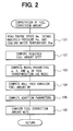
FIG. 2 is a flowchart showing the flow processes of a fuel correction amount computing program;
FIG. 3 is a block diagram schematically showing a system for compensating a fuel transportation lag;
FIG. 4 is a block diagram showing a first embodiment of a fuel transportation lag model;
FIG. 5 is a block diagram showing a fuel transportation lag model of a second embodiment; and
FIG. 6 is a block diagram showing a fuel transportation lag model of a third embodiment.
DETAILED DESCRIPTION OF THE PREFERRED EMBODIMENTS
The following description of preferred embodiment(s) is merely exemplary in nature and is in no way intended to limit the invention, its application, or uses.
A first embodiment of the invention will be described below with reference to FIGS. 1 through 4. First, the schematic configuration of an entire engine control system will be described by referring to FIG. 1. In the uppermost stream portion of an intake pipe 12 of internal combustion engine 11, an air cleaner 13 is provided. On the downstream side of the air cleaner 13, an air flow meter 14 for detecting an intake air volume is provided. On the downstream side of the air flow meter 14, a throttle valve 15 and a throttle angle sensor 16, for sensing a throttle angle, are provided. A surge tank 17 is provided downstream of the throttle valve 15, and the surge tank 17 is provided with an intake manifold pressure sensor 18 for sensing an intake manifold pressure Pm. The surge tank 17 is also provided with an intake manifold 19 for introducing air into all cylinders of the internal combustion engine 11. A fuel injection valve 20, for injecting fuel, is attached near the intake port of the intake manifold 19 of each cylinder.
At some point within the length of an exhaust pipe 21 of the engine 11, a catalyst 22 is disposed. The catalyst 22 may be a three-way catalyst for reducing CO, HC, NOx, and the like, in an exhaust gas. On the upstream side of the catalyst 22, an air-fuel ratio sensor 23 is provided for sensing the air-fuel ratio or a rich/lean state of the exhaust gas. To a cylinder block of the engine 11, a cooling water temperature sensor 24 for sensing a cooling water temperature Thw and a crank angle sensor 25 for sensing engine speed Ne are attached.
Outputs of the sensors are input to an engine control unit (described below as “ECU”) 26. The ECU 26 is constructed by using a microcomputer as a main body. The ECU 26 calculates a fuel correction amount WETC for compensating a fuel transportation lag of a fuel transportation system. The fuel transportation system transports the fuel injected from the fuel injection valve 20 to each cylinder by executing a fuel correction amount computing program of FIG. 2 stored in a built-in ROM (storage medium). A required fuel amount GFET is corrected by the fuel correction amount WETC, thereby obtaining a final fuel injection amount GF (injection time). Fuel injection is executed by applying an injection signal having a pulse width according to the fuel injection amount GF to the fuel injection valve 20 at the time of each injection.
A method of computing the fuel correction amount WETC from the fuel transportation lag model will now be described by referring to FIG. 3. The fuel transportation lag model has a configuration such that a fuel transportation lag element A, due to adhesion of the injected fuel on the wall face of the intake port and associated parts, and a first-order lag element B, for compensating a model error of the fuel transportation lag element A, are coupled in series. Fluctuations in the air-fuel ratio at the time of acceleration/deceleration are caused not only by the fuel transportation lag due to the adhesion of the injected fuel to the wall face, but also by factors such as an error in measurement (estimation) of an air volume charged in a cylinder. The error in measurement (estimation) of the cylinder charging air volume can be approximated by the first-order lag of the fuel transportation lag. Consequently, as shown in FIGS. 3 and 4, by coupling the first-order lag element B to the fuel transportation lag element A, in series, the model error due to the error in measurement (estimation) of the cylinder charging air volume or the like can be compensated, so that the accuracy in calculating the fuel correction amount WETC can be improved.
The fuel transportation lag element A is expressed by the following Aquino equation:
MF(t)=(1−Δt/τMF(t−Δt)+X·GF(t−Δt)
where MF(t) is an amount of fuel adhered to the wall face at the present time t, Δt is an operation cycle, τ is a fuel vaporization time constant, MF(t−Δt) is an amount of fuel adhered to the wall face at the time of operation of last time, X is a fuel adhesion rate, and GF(t−Δt) is a fuel injection amount of operation of last time.
A fuel amount Gcy′ (an output of the fuel transportation lag element A) drawn into a cylinder, which is calculated from Aquino's equation, is expressed by the following equation:
Gcy′=(1−X)·GF+(1−a)·MF  (1)
where “a” is a fuel residual rate, a−1−Δt/τ,(1−X)·GF denotes an amount of fuel which is directly drawn into a cylinder without being adhered to the wall face, and (1−a)·MF is an amount of fuel which evaporates from the wall face and is drawn into the cylinder.
The amount Gcy of fuel taken into the cylinder after model error compensation (output of the first-order lag element B) is expressed by the following equation:
Gcy=Gcy′+a 2 {Gcy(t−Δt)−Gcy′}  (2)
where a2=1−Δt/τ2 2 is a time constant of the first-order lag element B)
When the equation (1) is substituted into equation (2), the following equation is derived:
Gcy=(1−X)·GF·(1−a 2)+(1−a)·MF·(1−a 2)+a 2 ·Gcy(t−Δt)  (3)
When Gcy=GFET and Gcy(t−Δt)=GFET(t−Δt), the following equation is obtained.
[Equation 1] G F = G F E T ( 1 - X ) ( 1 - a 2 ) - 1 - a 1 - X · M F - a 2 ( 1 - X ) ( 1 - a 2 ) · G F E T ( t - Δ t ) ( 4 )
Figure US06748314-20040608-M00001
The final fuel injection amount GF is calculated by adding the fuel correction amount WETC to the required fuel amount GFET.
GF=GFET+WETC  (5)
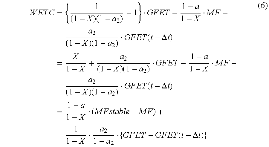
When the equation (5) is substituted for GF in equation (4) to solve for the fuel correction amount WETC, the following equation is obtained:
[Equation 2] W E T C = { 1 ( 1 - X ) ( 1 - a 2 ) - 1 } · G F E T - 1 - a 1 - X · M F - a 2 ( 1 - X ) ( 1 - a 2 ) · G F E T ( t - Δ t ) = X 1 - X + a 2 ( 1 - X ) ( 1 - a 2 ) · G F E T - 1 - a 1 - X · M F - a 2 ( 1 - X ) ( 1 - a 2 ) · G F E T ( t - Δ t ) = 1 - a 1 - X · ( M F s t a b l e - M F ) + 1 1 - X · a 2 1 - a 2 · { G F E T - G F E T ( t - Δ t ) } ( 6 )
Figure US06748314-20040608-M00002
where, MFstable denotes a cylinder wall face adhered fuel amount which is an amount of fuel stably adhered to the inner wall face of the intake system in a steady driving mode. In the steady driving mode, MF(t)=MF(t−Δt)=MFstable, GF(t)=GF(t−Δt), and Gcy′=Gcy=Gy. Consequently, the following equation is obtained from equation (1).
[Equation 3] M F s t a b l e = X 1 - a · G F ( 7 )
Figure US06748314-20040608-M00003
When the parameter (1−a)/(1−X) in the first term of the equation (6) is set as a first reference adaptation parameter b1 and the parameter 1/(1−X)·a2/(1−a 2) is set as a second reference adaptation parameter b2, the fuel correction amount WETC is calculated by the following equation.
WETC=b 1·(MFstable−MF)+b 2 ·{GFET−GFET(t−Δt)}  (8)
In the above equation, b1·(MFstable−MF) of the first term is a compensation term for the fuel transportation lag element A (calculation term of the first wall face adhesion correction amount), and b2·{GFET−GFET(t−Δt)} of the second term is a compensation term (calculation term of the second wall face adhesion correction amount) for the first-order lag element B. Further, in order to facilitate adaptation to an actual vehicle, it is sufficient to calculate the fuel correction amount WETC by the following equation in which the first and second terms are multiplied by a first correction factor k1 and a second correction factor K2, respectively, as shown in:
WETC=b 1 ·k 1·(MFstable−MF)+b 2 ·k 2 ·{GFET−GFET(t−Δt)}  (9)
By the above equation, the first wall face adhesion correction amount is obtained by multiplying the deviation between the wall face adhesion fuel amount MFstable in the steady driving mode and the wall face adhesion fuel amount MF at the present time by the first reference adaptation parameter b1 and the first correction factor k1. Duration of the first wall face adhesion correction amount may be expressed by a function of the fuel evaporation time constant τ. The second wall face adhesion correction amount is obtained by multiplying the deviation between the required fuel amount GFET of this time and the required fuel amount GFET(t−Δt) of the last time by the second reference adaptation parameter b2 and the second correction factor k2.
The adaptation parameters (reference adaptation parameters b1 and b2 and correction factors k1 and k2) may be adapted by one of the following methods (a) and (b).
(a) By setting each of the correction factors k1 and k2 to 1, the reference adaptation parameters b1 and b2 are adapted from a map or the like in accordance with the fluctuations in the air-fuel ratio.
(b) By using a system identification value or a physical measurement value as each of the reference adaptation parameters b1 and b2 the correction factors k1 and k2 are adapted from a map or the like in accordance with fluctuations in the air-fuel ratio.
The details of the processes of the fuel correction amount computing program of FIG. 2 will now be described. The program is executed periodically and synchronously with an injection timing of each cylinder. When the program is started, first, in step 101, the engine speed Ne, intake manifold pressure Pm, and cooling water temperature Thw (temperature information in place of the wall face temperature of the intake manifold 19) detected by the sensors 25, 18, and 24, respectively, are read. In step 102, the required fuel amount GFET is calculated by the following equation:
GFET=basic injection amount×air-fuel ratio learn value ×(after-start increase amount factor +OTP increase amount factor)
where required fuel amount GFET is an amount of fuel to be drawn into the cylinder in the steady driving mode. The basic injection amount is obtained from a map or the like in accordance with engine operation parameters such as the engine speed Ne and intake manifold pressure Pm. The air-fuel ratio learn value is a learn value for correcting a deviation of the air-fuel ratio due to a change in time or the like. The after-start increase amount factor is a fuel correction factor for correcting cylinder wetting which occurs immediately after starting and the like, and the OTP increase amount factor is a fuel correction factor for correcting the injection amount so as to be increased to protect the catalyst 22 and the like at the time of high load.
After computing the required fuel amount GFET, the program advances to step 103 where model parameters a, X, and a2 of the fuel transportation lag model are calculated by the following equations using two-dimensional maps map11 through map32:
a=map11(Ne, Pm)×map12(Ne, Thw)
X=map21(Ne, Pm)×map22(Ne, Thw)
a 2=map31(Ne, Pm)×map32(Ne, Thw)
where, each of map11(Ne, Pm), map21(Ne, Pm), and map31(Ne, Pm) is a two-dimensional map using the engine speed Ne and the intake manifold pressure Pm as variables, and each of map12(Ne, Thw), map22(Ne, Thw), and map32(Ne, Thw) is a two-dimensional map using the engine speed Ne and the cooling water temperature Thw as variables. In this case, a=1−Δt/τ (where τ denotes a fuel vaporization time constant) and a2=1−Δt/τ2 (where τ2 is a time constant of the first-order lag element B).
In this case, in order to satisfy the relation that the wall face adhesion fuel amount MFstable in the steady driving mode is almost proportional to the intake manifold pressure Pm and hardly changes with the engine speed Ne also in the case where the wall face temperature (cooling water temperature Thw) of the intake manifold 19 is low, the correction term by the wall face temperature (cooling water temperature Thw) has to be made variable also with the engine speed Ne. For this purpose, in the first embodiment, the correction term by the wall face temperature (cooling water temperature Thw) is calculated from two-dimensional maps map12(Ne, Thw), map22(Ne, Thw), and map32(Ne, Thw) using the engine speed Ne and the cooling water temperature Thw as variables.
After computing the model parameters a, X, and a2, the program advances to step 104 where the wall face adhesion fuel amount MF is calculated by the following equation:
MF(t)=(1−t/τ)·MF(t−Δt)+X·GF(t−Δt)
where MF(t) is an amount of fuel adhered to the wall face at a time t, Δt is an operation period (for example, interval of injections of each cylinder), τ is fuel vaporization time constant, MF(t−Δt) is an amount of fuel adhered to the wall face at the time of operation of last time, and GF(t−Δt) is a fuel injection amount of operation of last time. When the operation cycle At is set to an injection interval (720° CA) of each cylinder, MF(t−Δt) is a wall face adhesion fuel amount before 720° CA, and GA(t−Δt) is a fuel injection amount before 720° CA.
After that, the program advances to step 105 where the adaptation parameters (reference adaptation parameters b1 and b2 and correction factors k1 and k2) are adapted by any of the following methods (a) and (b).
(a) By setting each of the correction factors k1 and k2 to 1, the reference adaptation parameters b1, and b2 are adapted from a map or the like in accordance with a fluctuation in the air-fuel ratio.
(b) By using a system identification value or a physical measurement value as each of the reference adaptation parameters b1 and b2, the correction factors k1 and k2 are adapted from a map or the like in accordance with a fluctuation in the air-fuel ratio.
After that, the program advances to step 106 where the fuel correction amount WETC is calculated by the following equation using the reference adaptation parameters b1 and b2 and correction factors k1 and k2.
WETC=b 1 ·k 1·(MFstable−MF)+b 2 ·k 2 ·{GFET−GFET(t−Δt)}
According to the foregoing first embodiment, the fuel correction amount WETC can be calculated by the small number of adaptation parameters (reference adaptation parameters b1 and b2 and correction factors k1 and k2) and the number of adaptation steps for adapting the system to an actual vehicle can be made small. Therefore, a low development cost can be achieved, the operating process can be simplified, and the load on the CPU can also be reduced.
In the first embodiment, in the compensation term for the fuel transportation lag element A, the first wall face adhesion correction amount is obtained by multiplying the deviation between the wall face adhesion fuel amount MFstable in the steady driving mode and the wall face adhesion fuel amount MF at a present time by the first reference adaptation parameter b1 and the first correction factor k1. However, in place of the deviation between the wall face adhesion fuel amount MFstable in the steady driving mode and the wall face adhesion fuel amount MF at a present time, a deviation between a present intake manifold pressure and a smoothed intake manifold pressure (obtained by lagging the intake manifold pressure by the fuel vaporization time constant τ so as to have a first-order lag), or a deviation between a present intake air volume and a smoothed intake air volume (obtained by lagging the intake air volume by the fuel vaporization time constant τ so as to have a first-order lag) may be used.
In the first embodiment, in the compensation term for the first-order lag element B, the second wall face adhesion correction amount is obtained by multiplying the deviation between the required fuel amount GFET of a present time and the required fuel amount GFET(t−Δt) of last time by the second reference adaptation parameter b2 and the second correction factor k2. However, in place of the deviation between the required fuel amount GFET of a present time and the required fuel amount GFET(t−Δt) of last time, a deviation between an intake manifold pressure of this time and an intake manifold pressure of last time may be used.
The operation cycle Δt is not limited to the injection interval (720° CA) of each cylinder but may be set to a cycle other than the injection interval.
In a second embodiment of a fuel transportation lag model of FIG. 5, the relation between the wall face adhesion fuel amount MFstable in the steady driving mode and the required fuel amount GFET is approximated by the following equation: M F s t a b l e = X 1 - a · G F E T ( 7 )
Figure US06748314-20040608-M00004
GFET in the above equation is approximate to GF in Equation 7.
The wall face adhesion fuel amount MF at a present time is obtained by lagging the wall face adhesion fuel amount MFstable in the steady driving mode by the fuel vaporization time constant τ so as to have a first-order lag. By multiplying the deviation between the wall face adhesion fuel amount MFstable in the steady driving mode and the wall face adhesion fuel amount MF at the present time by the first reference adaptation parameter b1=(1−a)/(1−X), the first wall face adhesion correction amount equals (MFstable−MF)×b1.
In a third embodiment, a fuel transportation lag model of FIG. 6 is obtained by multiplying the first reference adaptation parameter b1, with the parameter X/(1−a) for converting the required fuel amount GFET into the wall face adhesion fuel amount MFstable in the steady driving mode so that the parameters are integrated to a single adaptation parameter X/(1−X). Therefore, in the fuel transportation lag mode of FIG. 6, the deviation between the required fuel amount GFET and the value GFET′, obtained by lagging the required fuel amount GFET by the fuel vaporization time constant τ so as to have a first-order lag, is multiplied by the adaptation parameter X/(1−X), thereby obtaining the first wall face adhesion correction amount equal to (GFET−GFET′)·X/(1−X).
The description of the invention is merely exemplary in nature and, thus, variations that do not depart from the gist of the invention are intended to be within the scope of the invention. Such variations are not to be regarded as a departure from the spirit and scope of the invention.

Claims (11)

What is claimed is:
1. A fuel injection amount control system for an internal combustion engine, comprising a compensation term for compensating a fuel transportation lag by using a fuel transportation lag model obtained by modeling a fuel transportation lag of a fuel transportation system for transporting a fuel injected from a fuel injection valve into an intake system so as to be taken into a cylinder of an internal combustion engine,
wherein physical parameters including at least one of a fuel vaporization time constant and a wall face adhesion rate of an injected fuel, included in the fuel transportation lag model, are converted to adaptation parameters; and
the adaptation parameters include a reference adaptation parameter and a correction factor, and one of a system identification value and a physical measurement value is used as the reference adaptation parameter, and a wall face adhesion correction amount, obtained by using the reference adaptation parameter, is corrected by the correction factor.
2. The fuel injection amount control system for an internal combustion engine according to claim 1, wherein the fuel transportation lag model has a configuration that a fuel transportation lag element A due to adhesion of the injected fuel onto the wall face and a first-order lag element B, for compensating a model error of the fuel transportation lag element A, are coupled in series.
3. The fuel injection amount control system for an internal combustion engine according to claim 2, wherein an equation for computing a fuel correction amount by using the fuel transportation lag model includes a compensation term for the fuel transportation lag element A and a compensation term for the first-order lag element B.
4. The fuel injection amount control system for an internal combustion engine according to claim 3, wherein in a compensation term for the first-order lag element B, a second wall adhesion correction amount is obtained by multiplying one of a deviation between a required fuel amount of a present time and a required fuel amount of last time and a deviation between an intake manifold pressure of a present time and an intake manifold pressure of last time with a second reference adaptation parameter and a second correction factor.
5. A fuel injection amount control system for an internal combustion engine, comprising a compensation term for compensating a fuel transportation lag by using a fuel transportation lag model obtained by modeling a fuel transportation lag of a fuel transportation system for transporting a fuel injected from a fuel injection valve into an intake system so as to be taken into a cylinder of an internal combustion engine,
wherein physical parameters including at least one of a fuel vaporization time constant and a wall face adhesion rate of an injected fuel, included in the fuel transportation lag model, are converted to adaptation parameters; and
the fuel transportation lag model has a configuration that a fuel transportation lag element A due to adhesion of the injected fuel onto the wall face and a first-order lag element B, for compensating a model error of the fuel transportation lag element A, are coupled in series.
6. The fuel injection amount control system for an internal combustion engine according to claim 5, wherein an equation for computing a fuel correction amount by using the fuel transportation lag model includes a compensation term for the fuel transportation lag element A and a compensation term for the first-order lag element B.
7. The fuel injection amount control system for an internal combustion engine according to claim 6, wherein in a compensation term for the first-order lag element B, a second wall adhesion correction amount is obtained by multiplying one of a deviation between a required fuel amount of a present time and a required fuel amount of last time and a deviation between an intake manifold pressure of a present time and an intake manifold pressure of last time with a second reference adaptation parameter and a second correction factor.
8. A fuel injection amount control system for an internal combustion engine, comprising a compensation term for compensating a fuel transportation lag by using a fuel transportation lag model obtained by modeling a fuel transportation lag of a fuel transportation system for transporting a fuel injected from a fuel injection valve into an intake system so as to be taken into a cylinder of an internal combustion engine,
wherein physical parameters including at least one of a fuel vaporization time constant and a wall face adhesion rate of an injected fuel, included in the fuel transportation lag model, are converted to adaptation parameters; and
in a compensation term for the fuel transportation lag, a first wall face adhesion correction amount is obtained by multiplying one of a deviation between a wall face adhesion fuel amount in a steady driving mode and a wall face adhesion fuel amount at a present time, a deviation between a present intake manifold pressure and a smoothed intake manifold pressure, and a deviation between a present intake air volume and a smoothed intake air volume with a first reference adaptation parameter and a first correction factor.
9. The fuel injection amount control system for an internal combustion engine according to claim 8, wherein duration of the first wall face adhesion correction amount is expressed by a function of the fuel vaporization time constant.
10. The fuel injection amount control system for an internal combustion engine according to claim 9, wherein in a compensation term for a first-order lag element B, a second wall adhesion correction amount is obtained by multiplying one of a deviation between a required fuel amount of this time and a required fuel amount of last time and a deviation between an intake manifold pressure of this time and an intake manifold pressure of last time with a second reference adaptation parameter and a second correction factor.
11. The fuel injection amount control system for an internal combustion engine according to claim 8, wherein in a compensation term for a first-order lag element B, a second wall adhesion correction amount is obtained by multiplying one of a deviation between a required fuel amount of a present time and a required fuel amount of last time and a deviation between an intake manifold pressure of a present time and an intake manifold pressure of last time with a second reference adaptation parameter and a second correction factor.
US10/059,406 2001-02-05 2002-01-31 Fuel injection amount control system for internal combustion engine Expired - Lifetime US6748314B2 (en)

Applications Claiming Priority (3)

Application Number Priority Date Filing Date Title
JP2001027813A JP4581038B2 (en) 2001-02-05 2001-02-05 Fuel injection amount control device for internal combustion engine
JP2001-27813 2001-02-05
JP2001-027813 2001-02-05

Publications (2)

Publication Number Publication Date
US20020133287A1 US20020133287A1 (en) 2002-09-19
US6748314B2 true US6748314B2 (en) 2004-06-08

Family

ID=18892410

Family Applications (1)

Application Number Title Priority Date Filing Date
US10/059,406 Expired - Lifetime US6748314B2 (en) 2001-02-05 2002-01-31 Fuel injection amount control system for internal combustion engine

Country Status (2)

Country Link
US (1) US6748314B2 (en)
JP (1) JP4581038B2 (en)

Families Citing this family (3)

* Cited by examiner, † Cited by third party
Publication number Priority date Publication date Assignee Title
JP2003120367A (en) * 2001-10-15 2003-04-23 Honda Motor Co Ltd Fuel injection control device for internal combustion engine
FR2928417B1 (en) * 2008-03-06 2010-12-31 Peugeot Citroen Automobiles Sa METHOD FOR DETERMINING THE QUANTITY OF FUEL TO BE INJECTED AT THE STARTING OF AN INDIRECT INJECTION ENGINE
JP5883140B2 (en) * 2012-07-17 2016-03-09 本田技研工業株式会社 Control device for internal combustion engine

Citations (10)

* Cited by examiner, † Cited by third party
Publication number Priority date Publication date Assignee Title
US4388906A (en) * 1981-07-06 1983-06-21 Toyota Jidosha Kabushiki Kaisha Fuel injected engine control device and method performing wall-adhered fuel accounting
US4481928A (en) * 1981-07-06 1984-11-13 Toyota Jidosha Kabushiki Kaisha L-Jetronic fuel injected engine control device and method smoothing air flow meter overshoot
US5408973A (en) * 1993-11-26 1995-04-25 Spangjer; Keith G. Internal combustion engine fuel supply system and method
JPH07166923A (en) 1993-12-17 1995-06-27 Nippondenso Co Ltd Fuel supply controller for internal combustion engine
US5611315A (en) 1994-10-24 1997-03-18 Nippondenso Co., Ltd. Fuel supply amount control apparatus for internal combustion engine
US5988144A (en) * 1997-01-16 1999-11-23 Nissan Motor Co., Ltd. Engine air-fuel ratio controller
US6073073A (en) * 1996-06-25 2000-06-06 Honda Giken Kogyo Kabushiki Kaisha Air/fuel ratio control system for an internal combustion engine
US6397830B1 (en) 1999-09-27 2002-06-04 Denso Corporation Air-fuel ratio control system and method using control model of engine
US6513488B2 (en) * 2000-09-18 2003-02-04 Mitsubishi Denki Kabushiki Kaisha Fuel injection control apparatus for direct injection type internal combustion engine
US6568240B1 (en) * 1999-01-11 2003-05-27 Ngk Spark Plug Co., Ltd. Method and apparatus using a gas concentration sensor for accurately controlling an air fuel ratio in an internal combustion engine

Patent Citations (10)

* Cited by examiner, † Cited by third party
Publication number Priority date Publication date Assignee Title
US4388906A (en) * 1981-07-06 1983-06-21 Toyota Jidosha Kabushiki Kaisha Fuel injected engine control device and method performing wall-adhered fuel accounting
US4481928A (en) * 1981-07-06 1984-11-13 Toyota Jidosha Kabushiki Kaisha L-Jetronic fuel injected engine control device and method smoothing air flow meter overshoot
US5408973A (en) * 1993-11-26 1995-04-25 Spangjer; Keith G. Internal combustion engine fuel supply system and method
JPH07166923A (en) 1993-12-17 1995-06-27 Nippondenso Co Ltd Fuel supply controller for internal combustion engine
US5611315A (en) 1994-10-24 1997-03-18 Nippondenso Co., Ltd. Fuel supply amount control apparatus for internal combustion engine
US6073073A (en) * 1996-06-25 2000-06-06 Honda Giken Kogyo Kabushiki Kaisha Air/fuel ratio control system for an internal combustion engine
US5988144A (en) * 1997-01-16 1999-11-23 Nissan Motor Co., Ltd. Engine air-fuel ratio controller
US6568240B1 (en) * 1999-01-11 2003-05-27 Ngk Spark Plug Co., Ltd. Method and apparatus using a gas concentration sensor for accurately controlling an air fuel ratio in an internal combustion engine
US6397830B1 (en) 1999-09-27 2002-06-04 Denso Corporation Air-fuel ratio control system and method using control model of engine
US6513488B2 (en) * 2000-09-18 2003-02-04 Mitsubishi Denki Kabushiki Kaisha Fuel injection control apparatus for direct injection type internal combustion engine

Also Published As

Publication number Publication date
JP4581038B2 (en) 2010-11-17
JP2002227683A (en) 2002-08-14
US20020133287A1 (en) 2002-09-19

Similar Documents

Publication Publication Date Title
CN100408836C (en) Calculation of air charge amount in internal combustion engine
US6636796B2 (en) Method and system for engine air-charge estimation
US6109244A (en) Fuel injection control apparatus for an internal combustion engine
US7831371B2 (en) Control apparatus for an internal combustion engine
US7305967B1 (en) Control apparatus for an internal combustion engine
US20040122584A1 (en) Pressure/temperature calculation apparatus
US20060020386A1 (en) Estimation of oxygen concentration in the intake manifold of an unthrottled lean burn engine
US7742870B2 (en) Air-fuel ratio control device of internal combustion engine
US6615812B2 (en) Method and arrangement for operating an internal combustion engine
US4911133A (en) Fuel injection control system of automotive engine
JP3610839B2 (en) Air-fuel ratio control device for internal combustion engine
JPS5925055A (en) Air-fuel ratio control device
JPS63314339A (en) Air-fuel ratio controller
JPH01237333A (en) Control device for internal combustion engine
US10995644B2 (en) Method for distinguishing between model inaccuracies and lambda offsets for a model-based control of the fill level of a catalytic converter
KR20180118227A (en) Method and system for determining non-gas constant and stoichiometric air-fuel ratio of fuel gas for a gas engine
US5611315A (en) Fuel supply amount control apparatus for internal combustion engine
EP0167839B1 (en) Fuel injection control apparatus for internal combustion engine
US6725149B2 (en) Electronic control device for internal combustion engine
US6748314B2 (en) Fuel injection amount control system for internal combustion engine
US9567931B2 (en) Cylinder-by-cylinder air-fuel ratio controller for internal combustion engine
US6550237B1 (en) Method and system for monitoring a catalytic converter
EP0339603B1 (en) Fuel supply control system for internal combustion engine
US20020152016A1 (en) Method for estimation of the quantity of fresh air present in the intake and exhaust manifolds of an internal combustion engine with a recirculation circuit
US6272423B1 (en) Method for correcting airflow in an internal combustion engine which is drawn in through an induction pipe and measured in the induction pipe

Legal Events

Date Code Title Description
AS Assignment

Owner name: DENSO CORPORATION, JAPAN

Free format text: ASSIGNMENT OF ASSIGNORS INTEREST;ASSIGNOR:DOHTA, HISAYO;REEL/FRAME:012550/0365

Effective date: 20020122

STCF Information on status: patent grant

Free format text: PATENTED CASE

FEPP Fee payment procedure

Free format text: PAYOR NUMBER ASSIGNED (ORIGINAL EVENT CODE: ASPN); ENTITY STATUS OF PATENT OWNER: LARGE ENTITY

FPAY Fee payment

Year of fee payment: 4

FPAY Fee payment

Year of fee payment: 8

FEPP Fee payment procedure

Free format text: PAYOR NUMBER ASSIGNED (ORIGINAL EVENT CODE: ASPN); ENTITY STATUS OF PATENT OWNER: LARGE ENTITY

FPAY Fee payment

Year of fee payment: 12