US6746221B1 - Traveling valve for sucker rod pumps - Google Patents
Traveling valve for sucker rod pumps Download PDFInfo
- Publication number
- US6746221B1 US6746221B1 US10/201,030 US20103002A US6746221B1 US 6746221 B1 US6746221 B1 US 6746221B1 US 20103002 A US20103002 A US 20103002A US 6746221 B1 US6746221 B1 US 6746221B1
- Authority
- US
- United States
- Prior art keywords
- piston
- housing
- aperture
- traveling valve
- interior
- Prior art date
- Legal status (The legal status is an assumption and is not a legal conclusion. Google has not performed a legal analysis and makes no representation as to the accuracy of the status listed.)
- Expired - Fee Related
Links
Images


Classifications
-
- F—MECHANICAL ENGINEERING; LIGHTING; HEATING; WEAPONS; BLASTING
- F04—POSITIVE - DISPLACEMENT MACHINES FOR LIQUIDS; PUMPS FOR LIQUIDS OR ELASTIC FLUIDS
- F04B—POSITIVE-DISPLACEMENT MACHINES FOR LIQUIDS; PUMPS
- F04B47/00—Pumps or pumping installations specially adapted for raising fluids from great depths, e.g. well pumps
- F04B47/02—Pumps or pumping installations specially adapted for raising fluids from great depths, e.g. well pumps the driving mechanisms being situated at ground level
-
- F—MECHANICAL ENGINEERING; LIGHTING; HEATING; WEAPONS; BLASTING
- F04—POSITIVE - DISPLACEMENT MACHINES FOR LIQUIDS; PUMPS FOR LIQUIDS OR ELASTIC FLUIDS
- F04B—POSITIVE-DISPLACEMENT MACHINES FOR LIQUIDS; PUMPS
- F04B53/00—Component parts, details or accessories not provided for in, or of interest apart from, groups F04B1/00 - F04B23/00 or F04B39/00 - F04B47/00
- F04B53/10—Valves; Arrangement of valves
- F04B53/12—Valves; Arrangement of valves arranged in or on pistons
- F04B53/125—Reciprocating valves
Definitions
- the present invention relates to fluid pumps for elevating fluids from areas such as subterranean hydrocarbon bearing formations. More particularly, the present invention relates to traveling valves for use on sucker rod pumps. In particular, the present invention relates to such traveling valve having sliding shear seals therein.
- Conventional oil and gas wells include a cased well bore with a tubing string extending down to the hydrocarbon bearing formation.
- the casing is perforated at the production level to permit the hydrocarbons to flow into the casing and the bottom of the tubing is generally open to permit the hydrocarbons to flow into the tubing and up to the surface.
- there is insufficient pressure in a formation to cause oil and other liquids to readily flow to the surface. It therefore becomes necessary to install some type of artificial lift system for pumping fluids to the surface.
- sucker rod pump One of the most common types of artificial lift systems is a sucker rod pump. This type of pump is positioned in the well at the level of the fluids to be removed and is mechanically driven by a series of rods connecting the pump to a pumping unit at the surface.
- a sucker rod pump includes the simple combination of a cylinder or barrel with a piston or plunger and a suitable intake valve and a discharge valve.
- the intake valve is often referred to as a standing valve and the discharge valve is often referred to as a traveling valve.
- Two of the more common types of sucker rod pumps are the tubing pump in which the pump barrel is attached directly to the tubing and is lowered to the bottom of the well as the tubing is run into the well.
- the plunger is attached to the bottom of the sucker rod and is positioned within the pump barrel.
- the intake valve is positioned at the bottom of the pump barrel and the traveling valve is positioned on the plunger.
- the second type of pump is often referred to as an insert pump and the entire assembly is attached to the bottom of the sucker rod.
- the barrel is held in place by a special seating nipple or other device positioned within the tubing.
- This type of pump has the advantage that it can more easily be removed for repair or replacement than a tubing pump. However, it suffers from the disadvantage of having a lower fluid capacity.
- the operation of a sucker rod pump is relatively simple.
- the plunger reciprocates up and down in the barrel under the force of the sucker rod.
- the traveling valve is closed and the fluid above the plunger is lifted to the surface by the plunger and sucker rod.
- the standing valve is open allowing fluids to flow into and fill the now evacuated barrel.
- the standing valve is closed thus trapping the fluids in the barrel.
- the traveling valve is opened allowing the compressed fluids to flow through the plunger so they can be lifted during the subsequent cycle.
- valves which are generally of the ball-and-seat variety. This type of valve is opened and closed by pressure differentials across the valve.
- gas lock This occurs when there is a substantial amount of gas that flows into the pump with the liquid. Because of the high compressibility of the gas, insufficient pressure is generated during the downstroke of the pump to open the traveling valve against the hydrostatic pressure of the fluid in the production tubing. Accordingly, the pump can repeatedly cycle without any fluid being lifted to the surface.
- Fluid pound is another problem that is often encountered. If the barrel is only partially filled with liquid the plunger forcefully encounters the liquid level part way through the downstroke thus causing severe stress to be placed on the pump. Pump off damage also occurs when the barrel is not completely filled with fluid. Damage occurs in the wall of the working barrel due to overheating of the pump which is caused by the absence of fluid to carry away the heat created by friction in the pump.
- the present invention is a traveling valve for use in a sucker rod pump comprising a cylindrical housing having an interior passageway and a piston received within the interior passageway and slidable therein.
- the housing has its interior passageway extending from an upper end thereof to a bottom end thereof.
- the interior passageway has a tapered shoulder formed therein.
- the piston has a mechanically operated sliding shear seal positioned interior of the housing. This seal is operable between open and closed positions by the reciprocal action of the sucker rod.
- the piston has a surface thereon generally conforming to a shape of the tapered surface in the interior passageway.
- the piston is movable between a first position and a second position.
- the seal is opened when the piston is in the first position.
- the seal is closed when the piston is in the second position.
- the surface of the piston is proximal the tapered shoulder of the housing when in the second position.
- a tubing has the housing and the piston interior thereof.
- the tubing defines an annulus between an inner wall thereof and an exterior of said housing.
- the housing has an aperture formed therein.
- the piston is in fluid communication with the annulus through the aperture when the piston is in the first position.
- the housing has a first channel extending through a wall thereof so as to communicate between the annulus and the interior passageway adjacent a top of the tapered shoulder.
- the housing also has a second channel extending through a wall thereof so as to communicate between the annulus and the interior passageway in a location below the tapered shoulder.
- the tapered shoulder has a frustoconical configuration.
- the surface of the piston has a frustoconical shape matching the frustoconical configuration of the tapered shoulder.
- the piston has a smaller diameter adjacent to the opening corresponding to the aperture of the housing when the piston is in the first position.
- the present invention includes a base which is threadedly connected to the lower end of the housing.
- This base includes a first semi-cylindrical portion positioned within the housing and containing a portion of the sliding shear seal.
- the piston is positioned within the housing above the base with a shaft extending through the upper end of said housing.
- the piston includes a second semi-cylindrical portion which matingly engages a first semi-cylindrical portion of the base and contains a second portion of the sliding shear seal.
- a first passageway extends substantially through the length of the base with a first end in the bottom of the base forming the inlet to the traveling valve and a second end positioned in a longitudinal planar surface of the first semi-cylindrical portion forming an opening in the sliding shear seal.
- An aperture extends through the second cylindrical portion of the piston. This aperture is in alignment with the second end of the first passageway when the valve is in the opened position.
- a plate is positioned in a longitudinal planar surface of a first semi-cylindrical portion. This plate has an aperture formed therein corresponding to the first passageway.
- a disk positioned within a recess of a longitudinal planar surface of the semi-cylindrical portion of the piston. This disk is aligned such that it occludes the aperture in the plate when the valve of the closed position.
- FIG. 1 is an exploded perspective view of the preferred embodiment of the present invention.
- FIG. 2 is a detailed illustration of the piston as used within the apparatus of the present invention.
- FIG. 3 is a perspective view of the assembled traveling valve of the present invention.
- FIG. 4 is a cross-sectional view showing the traveling valve of the present invention in an open position.
- FIG. 5 is a cross-sectional view of the traveling valve of the present invention showing the traveling valve in a closed position.
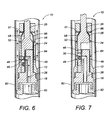
- FIG. 6 is a diagrammatic illustration of the operation of the present invention on the downstroke of the sucker rod.
- FIG. 7 is a diagrammatic illustration of the operation of the present invention with the sucker rod on the upstroke.
- the present invention provides a mechanically operated traveling valve assembly for use with sucker rod pumps.
- the valve assembly associated with the present invention eliminates the problems of gas lock, fluid pound and pump off damage that are often associated with conventional ball-and-seal type traveling valves. Additionally, since the traveling valve is mechanically operated, it can be used in any given attitude making it an excellent application for horizontal or deviated wells. Additionally, the structure of the present invention allows the traveling valve to withstand the strong forces imparted thereto over lengthy periods of time so as to enhance the operative life of the traveling valve.
- FIG. 1 illustrates an exploded perspective view of a preferred embodiment of the traveling valve 10 of the present invention generally designated at 10 .
- Valve 10 includes a cylindrical housing 12 having an upper end 14 and a lower end 15 .
- Base 16 having threads 18 is threadedly connected into the lower end 15 of housing 12 .
- Base 16 includes a semi-cylindrical portion 20 on the top thereof with a longitudinal planar surface 21 to form a portion of a sliding shear seal.
- a tungsten carbide plate 22 having an aperture 44 is placed within the longitudinal planar surface 21 of the semi-cylindrical portion 20 such that the surface of the plate is flush with the surface of the semi-cylindrical portion 20 .
- Plate 22 is secured in place by brazing or any other suitable means to hold it in place and provide a fluid-tight seal between plate 22 and base 16 .
- Base 16 also includes threads 19 to connect valve 10 to the top of a conventional plunger in a sucker rod pump.
- a piston 24 is positioned within housing 12 above base 16 .
- Piston 24 includes a shaft 26 which extends through aperture 13 in the upper end 14 of housing 12 .
- Piston 24 also includes a semi-cylindrical portion 28 on the bottom thereof with a longitudinal planar surface 29 which matingly engages semi-cylindrical portion 20 to form the other half of the sliding shear seal.
- a tungsten carbide disk 30 and a spring 32 are placed within a recess 34 (see FIG. 2) in semi-cylindrical portion 28 .
- Disk 30 engages plate 22 to form the remainder of the sliding shear seal.
- a hole 32 a is formed through semi-cylindrical portion 28 so as to allow hydrostatic pressure to act on the disk 30 .
- Valve 10 also includes a coupling 36 which is threadedly connected to the top of shaft 26 on piston 24 . Coupling 36 can then be interconnected to a sucker rod. Accordingly, valve 10 is mechanically operated between open and closed positions by the reciprocal action of the sucker rod on piston 24 .
- the piston 24 has a generally frustoconically shaped area 56 thereon.
- aperture 46 is formed through the wall of the semi-cylindrical portion 28 of piston 24 .
- a section 47 is formed in the area corresponding to aperture 46 of lesser diameter than the diameter of the piston 24 .
- This area of lesser diameter 46 allows fluids to flow outwardly of the aperture 46 , therearound and outwardly of the housing 12 through aperture 49 .
- Small channels 51 and 53 are formed through the wall of housing 12 so as to allow fluids in the annulus of the tubing string to flow toward the frustoconically-shaped surface 56 at the top of piston 24 .
- valve 10 When valve 10 is in the open position, an aperture 46 in the semi-cylindrical portion 28 of piston 24 is aligned with aperture 44 in plate 22 to allow the fluid to flow through the sliding shear seal. The fluid then flows through section 47 around piston 24 within housing 12 . Section 47 is formed on a side of piston 24 opposite the longitudinal planar surface 21 on semicylindrical portion 20 . The fluid can then pass through a passageway 49 toward the production tubing.
- FIGS. 4 and 5 show longitudinal cross-sectional views of valve 10 in its open and closed positions, respectively.
- Base 16 includes a passageway 38 extending substantially through the length thereof
- Passageway 38 includes a first opening 40 in the bottom of base 16 to permit fluids to flow into valve 10 .
- Passageway 38 includes a second opening 42 facing longitudinal planar surface 21 which permits the fluid to flow through aperture 44 in carbide plate 22 .
- valve 10 When valve 10 is in the open position, an aperture 46 in semi-cylindrical portion 28 of piston 24 is aligned with aperture 44 in plate 22 to allow the fluid to flow through the sliding shear seal. The fluid then flows through a section 47 around piston 24 within housing 12 . Section 47 is formed on a side of piston 24 opposite the longitudinal planar surface 21 on semicylindrical portion 20 . The fluid can then pass through passageway 49 and toward the production tubing.
- Piston 24 has a surface 56 which will move relative to the frustoconically-shaped tapered surface 58 on the interior of the housing 12 .
- surface 56 will be spaced from the frustoconically-tapered surface 58 on the interior of housing 12 .
- FIG. 5 it can be seen that, on the upstroke of the piston 24 , the surface 56 of the piston 24 will be proximal the tapered surface 58 on the interior of housing 12 .
- fluid channels 51 and 53 are provided through the wall of the housing 12 .
- the present invention provides a fluid-dampening effect against any shocks that might be imparted between the surface 26 of piston 24 and the surface 58 on the interior wall of the housing 12 .
- traveling valve 10 goes from the open position illustrated in FIG. 4 to the closed position illustrated in FIG. 5, disk 30 slides along plate 22 until it occludes aperture 44 in plate 22 . Disk 30 is urged against plate 22 to create a fluid tight seal by spring 32 by hydrostatic pressure of fluid above disk 30 through aperture 54 which places recess 34 in fluid communications with passageway 48 .
- valve 10 When valve 10 is in closed position, a surface 56 on piston 24 engages a tapered shoulder 58 in the upper end of housing 12 .
- the abutment of surface 56 with shoulder 58 positions disk 30 with plate 22 such that disk 30 occludes aperture 44 .
- Disk 30 is larger in diameter than aperture 44 . Additionally, the abutment of surface 56 with shoulder 58 transmits the force of the sucker rod during the upstroke to the remainder of valve 10 thus causing it to rise within the production tubing.
- piston 24 mechanically opens the sliding shear seal as disk 30 slides along plate 22 This allows any gas within the pump to escape through valve 10 and be replaced with fluid above valve 10 . This eliminates gas lock within the pump and reduces fluid pound and pump off by filling the barrel of the pump with fluid.
- FIG. 3 it can be seen that there is a section 47 of reduced diameter on the piston 24 .
- One of the problems associated with the prior art was the inability to fully flow the fluid outwardly of aperture 46 during the downstroke. By providing reduced diameter areas 47 and 47 a around the aperture 46 , fluid will be free to flow outwardly therethrough and therearound so that the fluid can exit aperture 49 in the housing 42 or other apertures formed around the housing 12 at the same level as aperture 49 . As such, it is not necessary for the present invention to pass the fluid outwardly in the small spaces between the piston 24 and the inner wall of the housing 12 .
- FIG. 2 also shows the configuration of the disk 30 as positioned within the recess 34 . Tapered surface 56 is illustrated as formed above a generally circular cross-sectioned area 70 on the piston 24 .
- FIG. 3 particularly illustrates the assembly of the traveling valve 10 of the present invention.
- the aperture 49 is formed through the wall of the housing 12 .
- channels 51 and 53 will also extend through the wall of housing 12 .
- multiple channels 51 and 53 can be formed through the walls of the housing 12 at the same level as those illustrated in FIG. 3 .
- additional apertures 49 can also be formed through the wall of the housing 12 at the same level as aperture 49 illustrated in FIG. 3 .
- FIG. 3 also shows the coupling 36 as secured to the threaded end of the shaft 26 of piston 24 .
- FIG. 6 shows the operation of the traveling valve 10 of the present invention in its position within working barrel 80 .
- annulus 84 is formed between the inner wall of the working barrel 80 and the outer surface of the housing 12 .
- Housing 12 is illustrated as having apertures 49 formed on opposite sides thereof.
- the base 16 is particularly illustrated in threaded engagement with the lower end of the housing 12 .
- the piston 24 is illustrated with its aperture 46 aligned with the aperture 49 of housing 12 .
- the passageway 38 in the base 16 will correspondingly align with the aperture 46 in the piston 24 .
- fluid from the annulus 84 will fill the space 86 between the outer surface of the piston 24 and the inner wall of the passageway associated with housing 12 .
- the filling of the space 86 is caused by the flow of fluid drawn through the channels 51 and 53 by the downward suction action created by the piston 24 on its downstroke.
- FIG. 6 it can be seen that fluid will flow upwardly through the annulus 84 of the working barrel 80 to a top surface location.
- FIG. 7 illustrates the piston 24 in its upstroke position.
- the traveling valve 10 of the present invention will be closed so as to lift fluid above the plunger 82 .
- the aperture 46 on the piston 24 has moved out of alignment with the aperture associated with fluid passageway 38 in the base 16 .
- disk 30 is moved in position by the spring 32 so as to be juxtaposed against the opening of the aperture associated with fluid passageway 38 .
- Hydrostatic pressure action through the aperture 49 and upon the surface of the disk 30 will further assure the sealing of the passageway 38 .
- While the principal use of the present invention is in oil wells, it is also designed to remove liquids, such as water, from gas wells.
- the fluids are removed in the tubing and the gases produced of the casing.
- the ability of the valve to eliminate gas lock, fluid pound and pump off damage makes it ideal for this application.
Landscapes
- Engineering & Computer Science (AREA)
- Mechanical Engineering (AREA)
- General Engineering & Computer Science (AREA)
- Details Of Reciprocating Pumps (AREA)
Abstract
Description
Claims (16)
Priority Applications (1)
| Application Number | Priority Date | Filing Date | Title |
|---|---|---|---|
| US10/201,030 US6746221B1 (en) | 2002-07-23 | 2002-07-23 | Traveling valve for sucker rod pumps |
Applications Claiming Priority (1)
| Application Number | Priority Date | Filing Date | Title |
|---|---|---|---|
| US10/201,030 US6746221B1 (en) | 2002-07-23 | 2002-07-23 | Traveling valve for sucker rod pumps |
Publications (1)
| Publication Number | Publication Date |
|---|---|
| US6746221B1 true US6746221B1 (en) | 2004-06-08 |
Family
ID=32324244
Family Applications (1)
| Application Number | Title | Priority Date | Filing Date |
|---|---|---|---|
| US10/201,030 Expired - Fee Related US6746221B1 (en) | 2002-07-23 | 2002-07-23 | Traveling valve for sucker rod pumps |
Country Status (1)
| Country | Link |
|---|---|
| US (1) | US6746221B1 (en) |
Cited By (6)
| Publication number | Priority date | Publication date | Assignee | Title |
|---|---|---|---|---|
| US20040113427A1 (en) * | 1999-12-03 | 2004-06-17 | Ernst Hugo A. | Assembly of hollow torque transmitting sucker rods and sealing nipple with improved seal and fluid flow |
| US20050025645A1 (en) * | 2003-07-30 | 2005-02-03 | Ford Michael Brent | Debris evacuation apparatus and method for an oil pump |
| US20060125234A1 (en) * | 2003-09-24 | 2006-06-15 | Siderca S.A.I.C. | Hollow sucker rod connection with second torque shoulder |
| US20090008080A1 (en) * | 2007-07-03 | 2009-01-08 | Charles David Willis | Stress and torque reducing tool |
| USD805114S1 (en) * | 2016-01-26 | 2017-12-12 | Roy Jones | Traveling rotary valve |
| USD917582S1 (en) * | 2019-01-25 | 2021-04-27 | Premium Tools Llc | Roller valve rod guide |
Citations (7)
| Publication number | Priority date | Publication date | Assignee | Title |
|---|---|---|---|---|
| US3136256A (en) * | 1962-10-12 | 1964-06-09 | United States Steel Corp | Subsurface pump and drive |
| US3215085A (en) * | 1963-09-09 | 1965-11-02 | Jack E Goostree | Standing valve assembly for downhole plunger pumps and attachment therefor |
| US3594103A (en) * | 1970-01-08 | 1971-07-20 | United States Steel Corp | Subsurface pump and method |
| US4448427A (en) * | 1983-06-10 | 1984-05-15 | Otis Engineering Corporation | Piston-expanded metallic seal for side door well valve |
| US4662831A (en) * | 1984-03-05 | 1987-05-05 | Bennett John D | Apparatus for fracturing earth formations while pumping formation fluids |
| US4968226A (en) * | 1989-04-28 | 1990-11-06 | Brewer Carroll L | Submergible reciprocating pump with perforated barrel |
| US5356114A (en) * | 1994-01-26 | 1994-10-18 | Mash Oil Tools, Inc. | Traveling valve for sucker rod pump |
-
2002
- 2002-07-23 US US10/201,030 patent/US6746221B1/en not_active Expired - Fee Related
Patent Citations (7)
| Publication number | Priority date | Publication date | Assignee | Title |
|---|---|---|---|---|
| US3136256A (en) * | 1962-10-12 | 1964-06-09 | United States Steel Corp | Subsurface pump and drive |
| US3215085A (en) * | 1963-09-09 | 1965-11-02 | Jack E Goostree | Standing valve assembly for downhole plunger pumps and attachment therefor |
| US3594103A (en) * | 1970-01-08 | 1971-07-20 | United States Steel Corp | Subsurface pump and method |
| US4448427A (en) * | 1983-06-10 | 1984-05-15 | Otis Engineering Corporation | Piston-expanded metallic seal for side door well valve |
| US4662831A (en) * | 1984-03-05 | 1987-05-05 | Bennett John D | Apparatus for fracturing earth formations while pumping formation fluids |
| US4968226A (en) * | 1989-04-28 | 1990-11-06 | Brewer Carroll L | Submergible reciprocating pump with perforated barrel |
| US5356114A (en) * | 1994-01-26 | 1994-10-18 | Mash Oil Tools, Inc. | Traveling valve for sucker rod pump |
Cited By (11)
| Publication number | Priority date | Publication date | Assignee | Title |
|---|---|---|---|---|
| US20040113427A1 (en) * | 1999-12-03 | 2004-06-17 | Ernst Hugo A. | Assembly of hollow torque transmitting sucker rods and sealing nipple with improved seal and fluid flow |
| US6991267B2 (en) * | 1999-12-03 | 2006-01-31 | Siderca S.A.I.C. | Assembly of hollow torque transmitting sucker rods and sealing nipple with improved seal and fluid flow |
| US20050025645A1 (en) * | 2003-07-30 | 2005-02-03 | Ford Michael Brent | Debris evacuation apparatus and method for an oil pump |
| US7404702B2 (en) * | 2003-07-30 | 2008-07-29 | Michael Brent Ford | Debris evacuation apparatus and method for an oil pump |
| US20060125234A1 (en) * | 2003-09-24 | 2006-06-15 | Siderca S.A.I.C. | Hollow sucker rod connection with second torque shoulder |
| US7431347B2 (en) | 2003-09-24 | 2008-10-07 | Siderca S.A.I.C. | Hollow sucker rod connection with second torque shoulder |
| US20090008080A1 (en) * | 2007-07-03 | 2009-01-08 | Charles David Willis | Stress and torque reducing tool |
| US7950449B2 (en) * | 2007-07-03 | 2011-05-31 | Harbison-Fisher, Inc. | Stress and torque reducing tool |
| US8215383B2 (en) | 2007-07-03 | 2012-07-10 | Harbison-Fischer, Inc. | Stress and torque reducing tool |
| USD805114S1 (en) * | 2016-01-26 | 2017-12-12 | Roy Jones | Traveling rotary valve |
| USD917582S1 (en) * | 2019-01-25 | 2021-04-27 | Premium Tools Llc | Roller valve rod guide |
Similar Documents
| Publication | Publication Date | Title |
|---|---|---|
| CA2503917C (en) | Apparatus and method for reducing gas lock in downhole pumps | |
| US4332533A (en) | Fluid pump | |
| US20200400242A1 (en) | Novel Valve Configuration | |
| US6585049B2 (en) | Dual displacement pumping system suitable for fluid production from a well | |
| US5533876A (en) | Pump barrel seal assembly including seal/actuator element | |
| US9856864B2 (en) | Reciprocating subsurface pump | |
| US5505258A (en) | Parallel tubing system for pumping well fluids | |
| US5628624A (en) | Pump barrel valve assembly including seal/actuator element | |
| US5314025A (en) | Fluid pumping apparatus and method of pumping fluid | |
| US4871302A (en) | Apparatus for removing fluid from the ground and method for same | |
| US10738575B2 (en) | Modular top loading downhole pump with sealable exit valve and valve rod forming aperture | |
| US5356114A (en) | Traveling valve for sucker rod pump | |
| US4557668A (en) | Down hole pump having a gas release valve | |
| US6746221B1 (en) | Traveling valve for sucker rod pumps | |
| US9784254B2 (en) | Tubing inserted balance pump with internal fluid passageway | |
| CA2901760C (en) | Modular top loading downhole pump | |
| RU2498058C1 (en) | Oil-well sucker-rod pumping unit for water pumping to stratum | |
| US4632647A (en) | Side entry down hole pump for oil wells | |
| US7048522B2 (en) | Fluid balanced pump | |
| RU2351801C1 (en) | Pump installation for simultaneous-separate operation of two reservoirs of one well | |
| US10519949B1 (en) | Superimposed standing valve | |
| US5104301A (en) | Sucker rod pump | |
| US2918014A (en) | Deep well pumping actuator | |
| US10132312B1 (en) | Superimposed standing valve | |
| RU2821685C1 (en) | Downhole sucker-rod pump of double action |
Legal Events
| Date | Code | Title | Description |
|---|---|---|---|
| AS | Assignment |
Owner name: HAVARD, JOHN DAVID, TEXAS Free format text: ASSIGNMENT OF ASSIGNORS INTEREST;ASSIGNOR:HAVARD, KENNETH;REEL/FRAME:014782/0342 Effective date: 20040618 Owner name: HAVARD, KENNETH SEELY, TEXAS Free format text: ASSIGNMENT OF ASSIGNORS INTEREST;ASSIGNOR:HAVARD, KENNETH;REEL/FRAME:014782/0342 Effective date: 20040618 |
|
| FPAY | Fee payment |
Year of fee payment: 4 |
|
| FPAY | Fee payment |
Year of fee payment: 8 |
|
| REMI | Maintenance fee reminder mailed | ||
| LAPS | Lapse for failure to pay maintenance fees | ||
| STCH | Information on status: patent discontinuation |
Free format text: PATENT EXPIRED DUE TO NONPAYMENT OF MAINTENANCE FEES UNDER 37 CFR 1.362 |
|
| STCH | Information on status: patent discontinuation |
Free format text: PATENT EXPIRED DUE TO NONPAYMENT OF MAINTENANCE FEES UNDER 37 CFR 1.362 |
|
| FP | Lapsed due to failure to pay maintenance fee |
Effective date: 20160608 |