US6741816B2 - Tone reproduction curve control method - Google Patents
Tone reproduction curve control method Download PDFInfo
- Publication number
- US6741816B2 US6741816B2 US10/214,940 US21494002A US6741816B2 US 6741816 B2 US6741816 B2 US 6741816B2 US 21494002 A US21494002 A US 21494002A US 6741816 B2 US6741816 B2 US 6741816B2
- Authority
- US
- United States
- Prior art keywords
- development
- potential
- vector
- trc
- backplating
- Prior art date
- Legal status (The legal status is an assumption and is not a legal conclusion. Google has not performed a legal analysis and makes no representation as to the accuracy of the status listed.)
- Expired - Fee Related, expires
Links
Images

Classifications
-
- G—PHYSICS
- G03—PHOTOGRAPHY; CINEMATOGRAPHY; ANALOGOUS TECHNIQUES USING WAVES OTHER THAN OPTICAL WAVES; ELECTROGRAPHY; HOLOGRAPHY
- G03G—ELECTROGRAPHY; ELECTROPHOTOGRAPHY; MAGNETOGRAPHY
- G03G15/00—Apparatus for electrographic processes using a charge pattern
-
- G—PHYSICS
- G03—PHOTOGRAPHY; CINEMATOGRAPHY; ANALOGOUS TECHNIQUES USING WAVES OTHER THAN OPTICAL WAVES; ELECTROGRAPHY; HOLOGRAPHY
- G03G—ELECTROGRAPHY; ELECTROPHOTOGRAPHY; MAGNETOGRAPHY
- G03G15/00—Apparatus for electrographic processes using a charge pattern
- G03G15/50—Machine control of apparatus for electrographic processes using a charge pattern, e.g. regulating differents parts of the machine, multimode copiers, microprocessor control
- G03G15/5033—Machine control of apparatus for electrographic processes using a charge pattern, e.g. regulating differents parts of the machine, multimode copiers, microprocessor control by measuring the photoconductor characteristics, e.g. temperature, or the characteristics of an image on the photoconductor
- G03G15/5041—Detecting a toner image, e.g. density, toner coverage, using a test patch
-
- G—PHYSICS
- G03—PHOTOGRAPHY; CINEMATOGRAPHY; ANALOGOUS TECHNIQUES USING WAVES OTHER THAN OPTICAL WAVES; ELECTROGRAPHY; HOLOGRAPHY
- G03G—ELECTROGRAPHY; ELECTROPHOTOGRAPHY; MAGNETOGRAPHY
- G03G2215/00—Apparatus for electrophotographic processes
- G03G2215/00025—Machine control, e.g. regulating different parts of the machine
- G03G2215/00029—Image density detection
- G03G2215/00033—Image density detection on recording member
- G03G2215/00037—Toner image detection
- G03G2215/00042—Optical detection
-
- G—PHYSICS
- G03—PHOTOGRAPHY; CINEMATOGRAPHY; ANALOGOUS TECHNIQUES USING WAVES OTHER THAN OPTICAL WAVES; ELECTROGRAPHY; HOLOGRAPHY
- G03G—ELECTROGRAPHY; ELECTROPHOTOGRAPHY; MAGNETOGRAPHY
- G03G2215/00—Apparatus for electrophotographic processes
- G03G2215/00025—Machine control, e.g. regulating different parts of the machine
- G03G2215/00029—Image density detection
- G03G2215/00033—Image density detection on recording member
- G03G2215/00054—Electrostatic image detection
Definitions
- the present invention relates to a method of controlling a printer, and more particularly, to an efficient tone reproduction curve (TRC) control method for providing images of high quality in response to environmental changes.
- TRC tone reproduction curve
- a usual electrophotographic process applied in printers includes charging a photosensitive body with electricity, exposing the charged photosensitive body to form a latent image in a particular image area, adhering a developer to an area of the latent image on the charged photosensitive body using a developing device, transferring the developed image to a sheet, and fixing the image using a fusing roller.
- the quality of the image can be increased by uniformly charging the photosensitive body with electricity. Accordingly, it is necessary to control the electric potential of the photosensitive body to be uniform during the charging.
- the charging potential is low, contamination can occur in a non-image area.
- the charging potential is high, developed mass per area (DMA) changes.
- DMA developed mass per area
- An electrostatic voltmeter or an electrometer is used for measuring the potential of the photosensitive body.
- the ESV is disposed near the surface of a photoreceptor belt so that it can measure the potential of the photosensitive body when the photoreceptor belt passes an electrostatic electrode.
- the potential of the photosensitive body is decreased to a predetermined potential referred to as an exposure potential to form the latent image during the exposure.
- the development device comes to have a development potential such that the potential of the developer is higher than the potential of a portion on which the latent image is formed, that is, the exposure potential, and lower than the potential of the other portion of the photoreceptor belt on which the latent image is not formed. As a result, the developer is made to adhere to an area of the latent image and thus development is performed.
- the DMA of the developer during development is influenced not only by the charging potential, as described above, but also by the exposure potential and the development potential.
- the exposure potential When the exposure potential is low, the difference between the exposure potential and the development potential is very big even if the development potential is maintained uniform. As a result, the amount of absorbed developer increases. When the exposure potential is high, the difference between the exposure potential and the development potential is small even if the development potential is maintained uniform. As a result, the amount of absorbed developer decreases, thereby producing a blurred image.
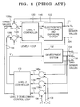
- FIG. 1 shows a method of controlling DMA to correct development errors in order to obtain an image of high quality, which is disclosed in U.S. Pat. No. 5,749,021.
- the charging potential, exposure potential, and development potential are controlled based on internal process parameters known as a discharge ratio, a cleaning potential and a development potential.
- This conventional method increases the quality of a printed image by controlling DMA in a process control loop.
- An area in which an image is formed is referred to as an image area.
- a test patch is usually provided between image areas to measure DMA.
- the measured DMA is compared with a target value, an error signal is transmitted to a controller, and the internal process parameters are adjusted, thereby correcting errors.
- a grid potential and an average beam power of an exposure system are calculated using the internal processes parameters to control the system of a printer.
- a level 1 controller 120 provides suitable control signals U g and U l to an electrostatic charging and exposure system 122 to control the electrostatic charging and exposure system 122 .
- Reference numeral 124 denotes a charging potential value V h and an exposure potential value V l of the electrostatic charging and exposure system 122 , which are measured by an ESV.
- Comparators 126 a and 126 b compare the values V h and V l with target values V h T and V l T denoted by reference numeral 128 for a charging potential and an exposure potential, respectively, and transmit error signals E h and E l , respectively, denoted by reference numeral 129 to the level 1 controller 120 .
- the gain of a level 1 loop is obtained from the error signals such that the potentials of a photosensitive body can converge to target values within a predetermined range.
- the target values V h T and V l T for the charging potential and exposure potential provided to the level 1 controller 120 and the electrostatic charging and exposure system 122 are generated from a level 2 controller 130 .
- Comparators 136 a , 136 b , and 136 c compare DMA sensor values D l , D m , and D h denoted by reference numeral 134 , which are measured from test patches provided according to a toner area coverage in a color toner density (CTD) sensor, with target values D l T , D m T , and D h T denoted by reference numeral 138 , respectively, and transmit error signals 139 to the level 2 controller 130 .
- the level 2 controller 130 generates a signal V T d for controlling a development system 132 .
- DMA values measured by a CTD sensor are compared with target DMA values to generate differences therebetween.
- the differences are transmitted to a level 2 controller.
- the level 2 controller linearizes internal process parameters, i.e., a discharge ratio, a cleaning potential, and a development potential and extracts target values for control parameters, i.e., a charging potential, an exposure potential, and a development potential, from the linearized discharge ratio, cleaning potential and development potential to control a level 1 controller and charging, exposure, and development systems.
- the conventional DMA control method disclosed in U.S. Pat. No. 5,749,021 uses not only a CTD sensor but also an electrostatic sensor in order to diagnose the status of all parameters influencing an electrophotographic process, which complicate measurement.
- the conventional DMA control method is not adaptive in a state in which a charging, exposure, or development system changes due to changes in external environmental parameters such as temperature and humidity of a printer, or due to internal environmental changes such as replacement or supplement of substances such as a developer or a photosensitive body included in the printer.
- the conventional DMA control method has a disadvantage of individually linearizing a discharge ratio, a cleaning potential, and a development potential in order to control a charging potential, an exposure potential, and a development potential based on internal process parameters, i.e., a discharge ratio, a cleaning potential, and a development potential.
- TRC toner reproduction curve
- a method of controlling a TRC in a printer including a color toner density (CTD) sensor receiving light reflected from test patches having different densities and photoelectrically converting the received light, the test patches being provided on a photoreceptor belt.
- CCD color toner density
- the step (a) includes the steps of (a-1) measuring a development potential V B , a charging potential V O , an exposure potential V R , and a development current Id; and (a-2) evaluating a development vector V D and a backplating vector V BP from the measured development potential V B , charging potential V O and exposure potential V R .
- the development vector V D and the backplating vector V BP satisfy the following formulae.
- V D V B ⁇ V R (1)
- V BP V O ⁇ V B (2)
- the step (b) includes the steps of (b-1) developing a test patch at a high toner area coverage, a test patch at a mid toner area coverage, and a test patch at a low toner area coverage on the photoreceptor belt and detecting a signal T H corresponding to the high toner area coverage, a signal T M corresponding to the mid toner area coverage, and a signal T L corresponding to the low toner area coverage from the CTD sensor receiving infrared rays reflected from the test patches and generating electrical signals; and (b-2) forming a TRC space using the detected signals T H , T M , and T L .
- the step (d) includes the steps of (d-1) deducing a development vector V D , a backplating vector V BP , and a development current Id by combining the TRC(T H , T M , T L ) data detected in step (b-1) with the TRC characteristic function obtained in step (c); (d-2) forming an RTRC(T RH , T RM , T RL ) space using TRC(T H , T M , T L ) data, whose covariance is smaller than the threshold value, among the TRC(T H , T M , T L ) data detected in step (b-1); and (d-3) determining a function having the development current Id as an independent parameter and the development vector V D as a dependent parameter and a function having the development current Id as an independent parameter and the backplating vector V BP as a dependent parameter by curve fitting the development vector V D , the backplating vector V BP , and the development current Id to be suitable to the
- the step (e) includes the steps of (e-1) measuring TRC(T H , T M , T L ) data in real time; (e-2) comparing the measured TRC(T H , T M , T L ) data with RTRC(T RH , T RM , T RL ) data; (e-3) calculating a development vector V D and a backplating vector V BP with respect to the measured development current Id from the TRC characteristic function obtained in step (c), when the deviation between the measured TRC(T H , T M , T L ) data and the RTRC(T RH , T RM , T RL ) data is greater than a tolerance error; (e-4) calculating a new development vector V D ′ and a new backplating vector V BP ′ by combining the measured development current Id with the functions of the development vector V D and the backplating vector V BP obtained in step (d-3); (e-5) calculating a value of a grid potential V G and
- the step (e) further includes the step of (e-7) estimating the efficiency of a charger from the development vector V D and the backplating vector V BP which are calculated in step (e-3) and from a development potential V B and a grid potential V G which are measured.
- the present invention controls a grid potential and a development potential by deducing the potentials (charging potential, exposure potential, and development potential) and development current of a photosensitive body which are necessary for maintaining and controlling the TRC of an apparatus such as an electrophotographic printer or a copy machine which uses an electrophotographic process.
- the potentials (charging potential, exposure potential, and development potential) of a photosensitive body are deduced using TRC data measured by a CTD sensor, without using an electrostatic sensor for measuring the charging potential and exposure potential of the photosensitive body and a sensor for measuring the development current.
- internal process parameters are a development vector, a backplating vector, and a development current which are defined above.
- a target RTRC value is set based on the result of deduction so that the TRC can approximate an RTRC to maintain or control the TRC.
- FIG. 1 is a diagram of a conventional system for controlling developed mass per area (DMA) to control image errors;
- DMA developed mass per area
- FIG. 2 is a schematic diagram of a printer to which a toner reproduction curve (TRC) control method according the present invention is applied;
- TRC toner reproduction curve
- FIG. 3 is a schematic diagram of a photoreceptor belt to which a TRC control method according the present invention is applied;
- FIG. 4 is a flowchart of a TRC control method according to an embodiment of the present invention.
- FIG. 5 is a flowchart of a TRC control method according to the embodiment of the present invention.
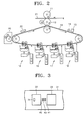
- FIG. 2 shows a printer to which the present invention is applied.
- the printer of FIG. 2 uses a typical electrophotographic process.
- the printer includes a charging unit 15 for charging the photosensitive body of a photoreceptor belt 13 ; development units 16 , 17 , 18 , and 19 which include a laser scanning unit (LSU) for exposing the charged photosensitive body to form a latent image and which adhere developers of different colors, i.e., yellow, cyan, magenta, and black, to the exposed portion of the photosensitive body to develop the image; a dry unit 20 for removing a carrier from the developed portion; a color toner density (CTD) sensor 22 for radiating infrared rays onto a developed test patch on the photoreceptor belt 13 , measuring the intensity of reflected light, and generating an electric signal corresponding to developed mass per area (DMA); a first transfer unit for transferring the image developed on the photoreceptor belt 13 to a medium transfer roller 12 contacting the photoreceptor belt 13 ; a second transfer unit including a fusing roller 11 and the medium transfer roller 12 for transferring the image on the medium transfer roller
- LSU laser
- a TRC is a graph of each of signals T H , T M , and T L detected by the CTD sensor 22 at each toner area coverage.
- FIG. 3 is a diagram of a portion of a photoreceptor belt where a CTD sensor is located to measure the TRC of a test patch.
- a CTD sensor is located to measure the TRC of a test patch.
- two image areas 33 are separated from each other on a photoreceptor belt 31 , and test patches 41 , 43 , and 45 are provided between the two image areas 33 .
- the test patches 41 , 43 , and 45 are divided into the test patch 41 at a high area coverage of 90-100%, the test patch 43 at a mid area coverage of around 50%, and the test patch 45 at a low area coverage of 0-20%.
- a CTD sensor 22 is provided to be separated from the photoreceptor belt 31 by a predetermined distance.
- the CTD sensor 22 radiates infrared rays onto the test patches 41 , 43 , and 45 and measures the intensity of reflected light.
- a signal detected from the test patch 41 at high area coverage is referred to as T H
- a signal detected from the test patch 43 at mid area coverage is referred to as T M
- a signal detected from the test patch 45 at low area coverage is referred to as T L .
- the actual density of a developer printed on each of the test patches 41 , 43 , and 45 can be optically measured using the CTD sensor 22 . As the density of a developer on the test patches 41 , 43 , and 45 gets higher, more light is absorbed into the test patches 41 , 43 , and 45 . Accordingly, the test patches 41 , 43 , and 45 sensed by an optical sensor appear darker.
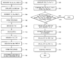
- FIG. 4 is a flowchart of the algorithm of a TRC control method according to an embodiment of the present invention.
- changes in external environments such as temperature and humidity which causes the characteristics of a developer or a photoreceptor belt to change, and internal environmental changes, such as replacement and supplement of the developer and replacement of the photoreceptor belt, should be considered.
- mass per area (M/A) can be expressed by Formula (4).
- M/A F (tone, V B , V G , P LD , V OPR , V RES , Id, ⁇ , %S, T, RH, . . . ) (4)
- tone denotes a toner area coverage
- P LD denotes a laser beam power
- V OPR denotes the charging potential of a photoreceptor belt
- V RES denotes the discharging potential of the photoreceptor belt
- ⁇ denotes the conductivity of a developer
- T denotes temperature
- RH denotes relative humidity.
- the development vector V D , the backplating vector V BP , and the development current Id are set as internal process parameters.
- the M/A in Formula (4) can be simplified as in Formula (5).
- a TRC characteristic equation can be obtained from tests. The following steps (a), (b), and (c) must be performed to obtain the TRC characteristic equation.
- Step (a) includes steps 100 and 102 .
- step 100 the development potential V B , charging potential V O , exposure potential V R , and development current Id are measured.
- step 102 Formulae (1) and (2) are applied to the measured development potential V B , charging potential V O , and exposure potential V R to evaluate the development vector V D and backplating vector V BP .
- Step (b) includes steps 104 and 106 .
- T H , T M , and T L are measured.
- the values of the development vector V D and backplating vector V BP evaluated in step 102 and the values of T H , T M , and T L measured in step 104 are shown in the following table.
- a TRC space is formed using the values of T H , T M , and T L .
- toner area coverages on test patches are set to a low area coverage of 20%, a mid area coverage of 50%, and a high area coverage of 80%.
- the TRC (tone) in Formula (6) can be expressed by Formula (7) with respect to signals T H , T M , and T L detected at the respective toner area coverages.
- T L H L (V D , V BP , Id, tone)
- T M H M (V D , V BP , Id, tone)
- T H H H (V D , V BP , Id, tone) (7)
- T L T M T H ⁇ [ A L A M A H ] ⁇ x 2 + [ B L B M B H ] ⁇ y 2 + [ C L C M C H ] ⁇ z 2 + [ D L D M D H ] ⁇ xy + ⁇ [ E L E M E H ] ⁇ yz + [ F L F M F H ] ⁇ zx + [ G L G M G H ] ( 8 )
- coefficients A N , B N , C N , D N , E N , F N , and G N can be obtained by performing curve fitting using the result of the test.
- T [ T L T M T H ]
- K [ A L B L C L D L E L F L G L A M B M C M D M E M F M G M A H B H C H D H E H F H G H ]
- V [ x 2 y 2 z 2 xy yz zx 1 ]
- x V D
- y V BP
- z Id ( 9 )
- Formula (8) combined with the results of the curve fitting is non-linear, so linearization at an arbitrary point P(x 0 , y 0 , z 0 ) is necessary for analysis of numerical values.
- a Jacobian matrix defined by Formula (11) should be obtained.
- J 21 2 A M x+D M y+F M z
- J 22 D M x +2 B M y+E M z
- J 23 F M x+E M y+ 2 C M z
- J 31 2 A H x+D H y+F H z
- J 32 D H x +2 B H y+E H z
- J 33 F H x+E H y +2 C H z
- Newton's method is performed as follows.
- second step third through seventh steps are repeated when k ⁇ N.
- “x” is output if ⁇ y ⁇ TOL.
- eighth step “Maximum number of iterations is reached” is output.
- the x, y, and z constitute an RTRC(T RH , T RM , T RL ).
- RTCR reference RTC
- the TRC control method deduces the charging potential V O , the exposure potential V R , and the development current Id using only the CTD sensor.
- the TRC control method includes detecting the quantity of light reflected from test patches having different toner area coverages on a photoreceptor belt using a CTD sensor and deducing a development vector V D , a backplating vector V BP , and a development current Id based on the detected outputs T RH , T RM , and T RL of the CTD sensor.
- a development potential V B and a grid potential V G are controlled based on the deduced values of the development vector V D , backplating vector V BP , and development current Id.
- Step (d) an RTRC space is formed.
- Step (d) includes steps 114 , 116 , and 118 .
- step 114 the development vector V D , the backplating vector V BP , and the development current Id are deduced by combining the TRC(T H , T M , T L ) data measured in step 104 with the TRC characteristic function obtained in step 108 .
- step 116 an RTRC(T RH , T RM , T RL ) space is formed using TRC(T H , T M , T L ) data, whose covariance is smaller than the threshold value, among the TRC(T H , T M , T L ) data measured in step 104 .
- a function having the development current Id as an independent parameter and the development vector V D as a dependent parameter and a function having the development current Id as an independent parameter and the backplating vector V BP as a dependent parameter are determined by curve fitting the development vector V D , the backplating vector V BP , and the development current Id to be suitable to the RTRC(T RH , T RM , T RL ) space formed in step 116 .
- the RTRC(T RH , T RM , T RL ) space is formed using TRC(T H , T M , T L ) data obtained based on the TRC(T H , T M , T L ) data measured in step 104 so as to satisfy Formula (13).
- “e” denotes the covariance of the TRC(T H , T M , T L ) data satisfying Formula (13) and is smaller than the threshold value.
- the functions satisfy Formula (14).
- a TRC characteristic equation is obtained from test data of measured development potential V B , charging potential V O , exposure potential V R , development current Id, T H , T M and T L . Then, the TRC(T H , T M , T L ) data is deduced from the TRC characteristic equation, and an RTRC(T RH , T RM , T RL ) is formed using TRC(T H , T M , T L ) data, whose covariance is smaller than a predetermined threshold value, among the deduced TRC(T H , T M , T L ) data.
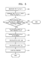
- FIG. 5 is a flowchart of step (e) in a TRC control method according to the embodiment of the present invention.
- step 200 the TRC(T H , T M , T L ) data is measured in real time.
- step 202 the TRC(T H , T M , T L ) data is compared with the RTRC(T RH , T RM , T RL ) data.
- the RTRC data of the printer is approximate to a target RTRC value, which means that the printer is in a normal state. Accordingly, the TRC control ends.
- step 206 a development vector V D and a backplating vector V BP with respect to the measured development current Id are calculated from the TRC characteristic function obtained in step 108 .
- step 208 the efficiency “m” of the charger 15 is estimated from the development vector V D and the backplating vector V BP calculated in step 206 and from the measured development potential V B and grid potential V G .
- V O V B + V BP ( 15 )
- V R V B - V D ( 16 )
- m V O V G ( 17 )
- a grid potential V G and a development potential V B which are control parameters, are calculated by combining the new development vector V D ′ and the new backplating vector V BP ′ calculated in step 210 with Formulae (18) through (21).
- V R a ⁇ ( V D ′ + V BP ′ ) 1 - a + b ( 18 )
- V B V R + V D ′ ( 19 )
- V O V R + V B + V BP ′ ( 20 )
- V G ⁇ ( V B + V BP ′ ) / m ( 21 )
- a” and “b” are the coefficients of a characteristic equation expressing the correlation between the charging potential V O and exposure potential V R of a photoreceptor belt and the power of a laser beam in a test.
- “a” and “b” were 0.382 and ⁇ 130, respectively. Since the exposure potential V R is more influenced by an initial charging potential V O of the photoreceptor belt immediately before exposure than by a change in the power of the laser beam, the exposure potential V R can be controlled by adjusting the grid potential V G influencing the charging potential V O .
- step 214 the charging potential V O , exposure potential V R and development current Id of the printer are adjusted by applying the grid potential V G and the development potential V B which are control parameters calculated from Formulae (18) through (21).
- the grid potential V G and the development potential V B By applying the grid potential V G and the development potential V B , a TRC approximating an RTRC can be obtained with respect to a changed development current Id.
- a TRC control method is characterized by an algorithm created by considering changes in the charging characteristics of a photosensitive body and in the characteristics of a developer. The changes are caused by internal and external environmental changes.
- a development vector V D a backplating vector V BP , and a development current Id instead of a grid potential, a laser beam power, and a development potential are selected as internal process parameters.
- the charging potential, exposure potential and development potential of the photosensitive body which vary with changes in an external environment such as time and temperature and internal environmental changes, can be deduced, and the performance of a charger can be estimated. Also, a state of the photosensitive body and developer can be evaluated, thereby allowing a user to know when the photosensitive body or developer should be replaced.
- a characteristic function can be obtained using TRC space data and RTRC space data which are set initially in a test, so productivity of development of the present invention is more excellent than a conventional method requiring creation of Jacobian matrixes for individual nominal values and a look-up table for the Jacobian matrixes.
- the charging potential of the photosensitive body can be estimated without using an electrostatic sensor.
- a TRC control method has advantages of measuring TRC data using only a CTD sensor and allowing TRC control to be performed considering environmental changes by forming TRC and RTRC spaces using a TRC characteristic equation having a development vector, a backplating vector, and a development current as parameters and by deducing the TRC space data and the RTRC space data.
- a single TRC space and a single RTRC space which are obtained through a test are sufficient for TRC control, which makes immediate control possible.
- the efficiency of a charger can be estimated from a charging potential deduced from the measured TRC data and a measured grid potential, and the characteristics of a photosensitive body and a developer can be estimated, thereby allowing a user to know when the photosensitive body and the developer should be replaced.
Landscapes
- Physics & Mathematics (AREA)
- General Physics & Mathematics (AREA)
- Engineering & Computer Science (AREA)
- Microelectronics & Electronic Packaging (AREA)
- Control Or Security For Electrophotography (AREA)
Abstract
Description
| VD | VBP | Id | TRC | ||
| X | y | z | TL | TM | TH | ||
| 184 | 290 | 200 | 3.031 | 4.035 | 5.699 | ||
| 214 | 260 | 200 | 3.006 | 4.383 | 5.682 | ||
| 244 | 230 | 200 | 2.811 | 4.447 | 5.699 | ||
| 274 | 200 | 200 | 2.963 | 4.530 | 5.765 | ||
| 197 | 260 | 200 | 3.018 | 4.259 | 5.511 | ||
| 227 | 230 | 200 | 3.160 | 4.369 | 5.507 | ||
| 257 | 200 | 200 | 3.397 | 4.435 | 5.577 | ||
| 287 | 170 | 200 | 3.463 | 4.611 | 5.575 | ||
| 208 | 230 | 200 | 3.324 | 4.225 | 5.534 | ||
| 238 | 200 | 200 | 3.329 | 4.323 | 5.502 | ||
| 268 | 170 | 200 | 3.471 | 4.508 | 5.578 | ||
| 298 | 140 | 200 | 3.518 | 4.714 | 5.605 | ||
| 184 | 290 | 264 | 2.342 | 4.325 | 5.607 | ||
| 214 | 260 | 264 | 2.340 | 4.300 | 5.672 | ||
| 244 | 230 | 264 | 2.828 | 4.427 | 5.690 | ||
| 274 | 200 | 264 | 2.584 | 4.410 | 5.787 | ||
| 197 | 260 | 264 | 2.320 | 4.256 | 5.536 | ||
| 227 | 230 | 264 | 2.472 | 4.386 | 5.607 | ||
| 257 | 200 | 264 | 2.689 | 4.566 | 5.663 | ||
| 287 | 170 | 264 | 2.467 | 4.796 | 5.807 | ||
| 208 | 230 | 264 | 2.987 | 4.483 | 5.531 | ||
| 238 | 200 | 264 | 2.889 | 4.493 | 5.589 | ||
| 268 | 170 | 264 | 2.701 | 4.593 | 5.668 | ||
| 298 | 140 | 264 | 3.136 | 4.811 | 5.748 | ||
| 184 | 290 | 324 | 2.457 | 4.362 | 5.336 | ||
| 214 | 260 | 324 | 2.709 | 4.486 | 5.536 | ||
| 244 | 230 | 324 | 2.511 | 4.755 | 5.467 | ||
| 274 | 200 | 324 | 2.836 | 4.857 | 5.668 | ||
| 197 | 260 | 324 | 2.704 | 4.388 | 5.424 | ||
| 227 | 230 | 324 | 2.572 | 4.598 | 5.514 | ||
| 257 | 200 | 324 | 2.762 | 4.713 | 5.568 | ||
| 287 | 170 | 324 | 2.884 | 4.857 | 5.660 | ||
| 208 | 230 | 324 | 2.784 | 4.395 | 5.394 | ||
| 238 | 200 | 324 | 2.709 | 4.642 | 5.441 | ||
| 268 | 170 | 324 | 3.009 | 4.686 | 5.557 | ||
| 298 | 140 | 324 | 3.087 | 4.911 | 5.636 | ||


Claims (25)


Applications Claiming Priority (2)
| Application Number | Priority Date | Filing Date | Title |
|---|---|---|---|
| KR10-2001-0048522A KR100378169B1 (en) | 2001-08-11 | 2001-08-11 | TRC control method |
| KR2001-48522 | 2001-08-11 |
Publications (2)
| Publication Number | Publication Date |
|---|---|
| US20030086717A1 US20030086717A1 (en) | 2003-05-08 |
| US6741816B2 true US6741816B2 (en) | 2004-05-25 |
Family
ID=19713123
Family Applications (1)
| Application Number | Title | Priority Date | Filing Date |
|---|---|---|---|
| US10/214,940 Expired - Fee Related US6741816B2 (en) | 2001-08-11 | 2002-08-09 | Tone reproduction curve control method |
Country Status (2)
| Country | Link |
|---|---|
| US (1) | US6741816B2 (en) |
| KR (1) | KR100378169B1 (en) |
Cited By (9)
| Publication number | Priority date | Publication date | Assignee | Title |
|---|---|---|---|---|
| US20050073724A1 (en) * | 2003-10-06 | 2005-04-07 | Xerox Corporation | Method for compensating for printer characteristics |
| US20060002722A1 (en) * | 2004-07-01 | 2006-01-05 | Kabushiki Kaisha Toshiba | System and method for detecting a life time of a developer |
| US20060153581A1 (en) * | 2005-01-11 | 2006-07-13 | Xerox Corporation | System and method for setup of toner concentration target for a toner concentration sensor |
| US20060153582A1 (en) * | 2005-01-11 | 2006-07-13 | Xerox Corporation | Method and system for using toner concentration as an active control actuator for TRC control |
| US20060153580A1 (en) * | 2005-01-11 | 2006-07-13 | Xerox Corporation | Tone reproduction curve and developed mass per unit area control method and system |
| US20060245773A1 (en) * | 2005-04-29 | 2006-11-02 | Xerox Corporation | Tone reproduction curve (TRC) target adjustment strategy for actuator set points and color regulation performance trade off |
| US20070140552A1 (en) * | 2005-12-21 | 2007-06-21 | Xerox Corporation | Optimal test patch level selection for systems that are modeled using low rank eigen functions, with applications to feedback controls |
| US20090009776A1 (en) * | 2007-07-03 | 2009-01-08 | Xerox Corporation | Adaptive cycle up convergence criteria |
| US20130114965A1 (en) * | 2010-08-15 | 2013-05-09 | YanFu Kuo | Tone reproduction curve error reduction |
Families Citing this family (5)
| Publication number | Priority date | Publication date | Assignee | Title |
|---|---|---|---|---|
| US6694109B1 (en) * | 2003-01-15 | 2004-02-17 | Xerox Corporation | Real-time control of tone reproduction curve by redefinition of lookup tables from fit of in-line enhanced toner area coverage (ETAC) data |
| KR100636185B1 (en) * | 2004-10-22 | 2006-10-19 | 삼성전자주식회사 | A color printer including a color compensation method and a color compensation unit of a color printer |
| KR100628568B1 (en) | 2004-11-08 | 2006-09-26 | 삼성전자주식회사 | Toner remaining amount measuring device, an image forming apparatus including the same and toner remaining amount measuring method |
| JP6805707B2 (en) * | 2016-10-13 | 2020-12-23 | コニカミノルタ株式会社 | Image forming device and image defect judgment program |
| JP6974945B2 (en) * | 2017-01-24 | 2021-12-01 | キヤノン株式会社 | Image forming device |
Citations (8)
| Publication number | Priority date | Publication date | Assignee | Title |
|---|---|---|---|---|
| US5436705A (en) * | 1994-04-18 | 1995-07-25 | Xerox Corporation | Adaptive process controller for electrophotographic printing |
| US5543896A (en) * | 1995-09-13 | 1996-08-06 | Xerox Corporation | Method for measurement of tone reproduction curve using a single structured patch |
| US5749020A (en) * | 1996-11-21 | 1998-05-05 | Xerox Corporation | Coordinitization of tone reproduction curve in terms of basis functions |
| US5749021A (en) * | 1996-12-04 | 1998-05-05 | Xerox Corporation | Developed mass per unit area (DMA) controller to correct for development errors |
| US5784667A (en) * | 1996-11-22 | 1998-07-21 | Xerox Corporation | Test patch recognition for the measurement of tone reproduction curve from arbitrary customer images |
| US5960232A (en) * | 1997-12-02 | 1999-09-28 | Tektronix, Inc | Method for controlling density in a printed image |
| US6035152A (en) * | 1997-04-11 | 2000-03-07 | Xerox Corporation | Method for measurement of tone reproduction curve |
| US6201936B1 (en) * | 1999-12-03 | 2001-03-13 | Xerox Corporation | Method and apparatus for adaptive black solid area estimation in a xerographic apparatus |
-
2001
- 2001-08-11 KR KR10-2001-0048522A patent/KR100378169B1/en not_active Expired - Fee Related
-
2002
- 2002-08-09 US US10/214,940 patent/US6741816B2/en not_active Expired - Fee Related
Patent Citations (8)
| Publication number | Priority date | Publication date | Assignee | Title |
|---|---|---|---|---|
| US5436705A (en) * | 1994-04-18 | 1995-07-25 | Xerox Corporation | Adaptive process controller for electrophotographic printing |
| US5543896A (en) * | 1995-09-13 | 1996-08-06 | Xerox Corporation | Method for measurement of tone reproduction curve using a single structured patch |
| US5749020A (en) * | 1996-11-21 | 1998-05-05 | Xerox Corporation | Coordinitization of tone reproduction curve in terms of basis functions |
| US5784667A (en) * | 1996-11-22 | 1998-07-21 | Xerox Corporation | Test patch recognition for the measurement of tone reproduction curve from arbitrary customer images |
| US5749021A (en) * | 1996-12-04 | 1998-05-05 | Xerox Corporation | Developed mass per unit area (DMA) controller to correct for development errors |
| US6035152A (en) * | 1997-04-11 | 2000-03-07 | Xerox Corporation | Method for measurement of tone reproduction curve |
| US5960232A (en) * | 1997-12-02 | 1999-09-28 | Tektronix, Inc | Method for controlling density in a printed image |
| US6201936B1 (en) * | 1999-12-03 | 2001-03-13 | Xerox Corporation | Method and apparatus for adaptive black solid area estimation in a xerographic apparatus |
Cited By (17)
| Publication number | Priority date | Publication date | Assignee | Title |
|---|---|---|---|---|
| US7352492B2 (en) * | 2003-10-06 | 2008-04-01 | Xerox Corporation | Method for compensating for printer characteristics |
| US20050073724A1 (en) * | 2003-10-06 | 2005-04-07 | Xerox Corporation | Method for compensating for printer characteristics |
| US20060002722A1 (en) * | 2004-07-01 | 2006-01-05 | Kabushiki Kaisha Toshiba | System and method for detecting a life time of a developer |
| US20060153581A1 (en) * | 2005-01-11 | 2006-07-13 | Xerox Corporation | System and method for setup of toner concentration target for a toner concentration sensor |
| US20060153582A1 (en) * | 2005-01-11 | 2006-07-13 | Xerox Corporation | Method and system for using toner concentration as an active control actuator for TRC control |
| US20060153580A1 (en) * | 2005-01-11 | 2006-07-13 | Xerox Corporation | Tone reproduction curve and developed mass per unit area control method and system |
| US7127187B2 (en) * | 2005-01-11 | 2006-10-24 | Xerox Corporation | Tone reproduction curve and developed mass per unit area control method and system |
| US7158732B2 (en) | 2005-01-11 | 2007-01-02 | Xerox Corporation | Method and system for using toner concentration as an active control actuator for TRC control |
| US7274887B2 (en) | 2005-01-11 | 2007-09-25 | Xerox Corporation | System and method for setup of toner concentration target for a toner concentration sensor |
| US20060245773A1 (en) * | 2005-04-29 | 2006-11-02 | Xerox Corporation | Tone reproduction curve (TRC) target adjustment strategy for actuator set points and color regulation performance trade off |
| US7239819B2 (en) * | 2005-04-29 | 2007-07-03 | Xerox Corporation | Tone reproduction curve (TRC) target adjustment strategy for actuator set points and color regulation performance trade off |
| US20070140552A1 (en) * | 2005-12-21 | 2007-06-21 | Xerox Corporation | Optimal test patch level selection for systems that are modeled using low rank eigen functions, with applications to feedback controls |
| US7590282B2 (en) * | 2005-12-21 | 2009-09-15 | Xerox Corporation | Optimal test patch level selection for systems that are modeled using low rank eigen functions, with applications to feedback controls |
| US20090009776A1 (en) * | 2007-07-03 | 2009-01-08 | Xerox Corporation | Adaptive cycle up convergence criteria |
| US8314959B2 (en) * | 2007-07-03 | 2012-11-20 | Xerox Corporation | Adaptive cycle up convergence criteria |
| US20130114965A1 (en) * | 2010-08-15 | 2013-05-09 | YanFu Kuo | Tone reproduction curve error reduction |
| US9014578B2 (en) * | 2010-08-15 | 2015-04-21 | Hewlett-Packard Development Company, L.P. | Tone reproduction curve error reduction |
Also Published As
| Publication number | Publication date |
|---|---|
| KR20030014495A (en) | 2003-02-19 |
| KR100378169B1 (en) | 2003-03-29 |
| US20030086717A1 (en) | 2003-05-08 |
Similar Documents
| Publication | Publication Date | Title |
|---|---|---|
| US6741816B2 (en) | Tone reproduction curve control method | |
| CN102279535B (en) | Image forming apparatus capable of performing accurate gradation correction | |
| US6493083B2 (en) | Method for measuring color registration and determining registration error in marking platform | |
| US8369729B2 (en) | Image forming apparatus with varying transfer bias | |
| US5216463A (en) | Electrophotographic process control device using a neural network to control an amount of exposure | |
| JPH10181104A (en) | Machine controlling method | |
| JPH0869145A (en) | Image forming device | |
| JP2017037100A (en) | Image forming apparatus and method of controlling the same | |
| US11818304B2 (en) | Image forming apparatus determining information related to a density of an image to be formed based on a determination condition | |
| EP3528488B1 (en) | Image processing apparatus, image processing system, and computer program product | |
| JP2004220030A (en) | Method and system for calibrating toner concentration sensor | |
| JP4582900B2 (en) | Image forming apparatus and noise effect correcting method | |
| US7498578B2 (en) | Method and system for calibrating a reflection infrared densitometer in a digital image reproduction machine | |
| US8010001B2 (en) | Specular diffuse balance correction method | |
| CN102478772B (en) | Image forming apparatus which controls setting of contrast potential | |
| Li et al. | Robust stabilization of tone reproduction curves for the xerographic printing process | |
| JP5064833B2 (en) | Image forming apparatus | |
| US5225872A (en) | Image forming apparatus having device for determining moisture absorption | |
| US6687470B2 (en) | Method of compensating for image quality by controlling toner reproduction curve | |
| US7995240B2 (en) | Image-forming device capable of forming and correcting color image | |
| JPH11258873A5 (en) | Image forming device | |
| EP2444849A2 (en) | Image forming apparatus capable of providing stable image quality | |
| KR100850712B1 (en) | Method and apparatus for controlling transfer voltage in image forming device | |
| CN100422867C (en) | Closed-loop control of photoreceptor surface voltage in electrophotographic process | |
| JP2023012287A (en) | image forming device |
Legal Events
| Date | Code | Title | Description |
|---|---|---|---|
| AS | Assignment |
Owner name: SAMSUNG ELECTRONICS CO., LTD., KOREA, REPUBLIC OF Free format text: ASSIGNMENT OF ASSIGNORS INTEREST;ASSIGNORS:SHIM, WOO-JUNG;KIM, MIN-SEON;REEL/FRAME:013502/0136 Effective date: 20020903 |
|
| FEPP | Fee payment procedure |
Free format text: PAYOR NUMBER ASSIGNED (ORIGINAL EVENT CODE: ASPN); ENTITY STATUS OF PATENT OWNER: LARGE ENTITY |
|
| FPAY | Fee payment |
Year of fee payment: 4 |
|
| FEPP | Fee payment procedure |
Free format text: PAYOR NUMBER ASSIGNED (ORIGINAL EVENT CODE: ASPN); ENTITY STATUS OF PATENT OWNER: LARGE ENTITY Free format text: PAYER NUMBER DE-ASSIGNED (ORIGINAL EVENT CODE: RMPN); ENTITY STATUS OF PATENT OWNER: LARGE ENTITY |
|
| FPAY | Fee payment |
Year of fee payment: 8 |
|
| REMI | Maintenance fee reminder mailed | ||
| LAPS | Lapse for failure to pay maintenance fees | ||
| STCH | Information on status: patent discontinuation |
Free format text: PATENT EXPIRED DUE TO NONPAYMENT OF MAINTENANCE FEES UNDER 37 CFR 1.362 |
|
| STCH | Information on status: patent discontinuation |
Free format text: PATENT EXPIRED DUE TO NONPAYMENT OF MAINTENANCE FEES UNDER 37 CFR 1.362 |
|
| FP | Lapsed due to failure to pay maintenance fee |
Effective date: 20160525 |
|
| AS | Assignment |
Owner name: S-PRINTING SOLUTION CO., LTD., KOREA, REPUBLIC OF Free format text: ASSIGNMENT OF ASSIGNORS INTEREST;ASSIGNOR:SAMSUNG ELECTRONICS CO., LTD;REEL/FRAME:041852/0125 Effective date: 20161104 |