JP2004220030A - Method and system for calibrating toner concentration sensor - Google Patents
Method and system for calibrating toner concentration sensor Download PDFInfo
- Publication number
- JP2004220030A JP2004220030A JP2004006166A JP2004006166A JP2004220030A JP 2004220030 A JP2004220030 A JP 2004220030A JP 2004006166 A JP2004006166 A JP 2004006166A JP 2004006166 A JP2004006166 A JP 2004006166A JP 2004220030 A JP2004220030 A JP 2004220030A
- Authority
- JP
- Japan
- Prior art keywords
- toner
- patch
- voltage
- patches
- toner density
- Prior art date
- Legal status (The legal status is an assumption and is not a legal conclusion. Google has not performed a legal analysis and makes no representation as to the accuracy of the status listed.)
- Pending
Links
Images


Classifications
-
- G—PHYSICS
- G03—PHOTOGRAPHY; CINEMATOGRAPHY; ANALOGOUS TECHNIQUES USING WAVES OTHER THAN OPTICAL WAVES; ELECTROGRAPHY; HOLOGRAPHY
- G03G—ELECTROGRAPHY; ELECTROPHOTOGRAPHY; MAGNETOGRAPHY
- G03G15/00—Apparatus for electrographic processes using a charge pattern
- G03G15/01—Apparatus for electrographic processes using a charge pattern for producing multicoloured copies
Landscapes
- Physics & Mathematics (AREA)
- General Physics & Mathematics (AREA)
- Control Or Security For Electrophotography (AREA)
- Dry Development In Electrophotography (AREA)
- Investigating Or Analysing Materials By Optical Means (AREA)
Abstract
Description
本発明は、一般的に、電子写真方式プリント装置に使用可能なトナー濃度センサに関する。 The present invention generally relates to a toner density sensor that can be used in an electrophotographic printing apparatus.
画像形成面の電気的パラメータをモニタ及び制御する装置がある(例えば、特許文献1参照。特許文献1の対象全体を本明細書に参照して援用する)。このモニタ制御装置はパッチ生成器を含み、パッチ生成器は、画像形成面に第1の電圧レベルで第1の制御パッチを記録し且つ第2の電圧レベルで第2の制御パッチを記録する。この装置は、第1及び第2の制御パッチと関連づけられた電位を測定する静電ボルトメータも含む。パッチ生成器と通信するプロセッサは、第1及び第2の制御パッチの測定電位から、画像形成面の電気的パラメータを計算する。プロセッサは、計算された電気的パラメータ値と設定値との間の偏差を決定する。 There are devices that monitor and control the electrical parameters of an image forming surface (see, for example, U.S. Pat. No. 6,074,839; the entire subject matter of U.S. Pat. The monitor controller includes a patch generator that records a first control patch at a first voltage level and a second control patch at a second voltage level on the imaging surface. The apparatus also includes an electrostatic voltmeter that measures a potential associated with the first and second control patches. A processor in communication with the patch generator calculates electrical parameters of the imaging surface from the measured potentials of the first and second control patches. The processor determines a deviation between the calculated electrical parameter value and the set value.
偏差が閾値レベルを超える場合には、プロセッサはフィードバックのエラー信号を生成してパッチ生成器に送る。次に、パッチ生成器は、エラー信号の受信に応答して、画像形成面に第3の電圧レベルで第3の制御パッチを記録する。静電ボルトメータは第3の制御パッチを検出する。プロセッサは、第3の制御パッチの測定電位から、画像形成面の電気的パラメータを計算し、補正係数を決定する。この補正係数に基づいて、帯電装置、露光システム及び現像器が調節される。所望の値への収束が達成されるまで、この3つのパッチのシーケンスが繰り返される。 If the deviation exceeds the threshold level, the processor generates a feedback error signal and sends it to the patch generator. Next, in response to receiving the error signal, the patch generator records a third control patch at the third voltage level on the image forming surface. The electrostatic voltmeter detects the third control patch. The processor calculates an electrical parameter of the image forming surface from the measured potential of the third control patch, and determines a correction coefficient. The charging device, the exposure system, and the developing device are adjusted based on the correction coefficient. The sequence of the three patches is repeated until convergence to the desired value is achieved.
現像材料粒子間、即ち、現像剤粒子とキャリア粒子との間の帯電が弱くなったことを決定するトナー濃度制御システムがある(例えば、特許文献2参照。特許文献2の対象全体を本明細書に参照して援用する)。現像材料粒子間の帯電が弱くなると、最初の数枚のコピーが期待よりも暗くなる。この状態が生じたことを決定するために、このシステムは、12%及び87%の反射率を有する(即ち、一方のパッチが入射光の約12%を反射し、他方のパッチが入射光の約87%を反射する)よう意図された2つのハーフトーン較正パッチを現像する。これらの2つのパッチの実際の反射率は、黒トナー領域被覆率センサによって読み取られ、記録される。例えば、75%(12%−87%)等といった、2つのパッチの測定反射率の差が計算される。差が大きいと、パッチが暗くなり過ぎたかどうかが良好に示される。反射率の差(デルタ)が目標値未満の場合には、トライボが許容範囲内であると見なされ、何も行われない。トライボとは、トナーキャリア粒子とトナー粒子との間の摩擦電気的関係の短縮名称であり、即ち、トナー粒子が、画像保持部材の帯電部分においてトナー粒子をキャリア粒子から引き離して光導電面に引き付ける極性を有する。しかし、差が目標値を超える場合には、プリントエンジンは特別停止リカバリセットアップの実行に移る。このセットアップは、トナーの摩擦電気帯電を高めてトナー材料を再活性化するために、まずシステムの調子を十分に上げ下げする。次に、システムは、トナー濃度設定及び静電気の収束の通常のセットアップ工程を続ける。完了したら、システムはオンラインに戻り、良好なコピー品質を生じる準備完了となる。特許文献2に開示されているこのシステムでは、トナー濃度センサを省くことができる。 There is a toner concentration control system that determines that the charge between the developing material particles, that is, between the developer particles and the carrier particles, has become weaker (for example, see Patent Document 2; the entire subject matter of Patent Document 2 is described herein). ). When the charge between the developer material particles is weakened, the first few copies will be darker than expected. To determine that this condition has occurred, the system has 12% and 87% reflectivity (ie, one patch reflects about 12% of the incident light and the other patch reflects the incident light). Develop two halftone calibration patches intended to reflect about 87%). The actual reflectivity of these two patches is read and recorded by a black toner area coverage sensor. For example, the difference between the measured reflectance of the two patches is calculated, such as 75% (12% -87%). A large difference is a good indication of whether the patch has become too dark. If the reflectivity difference (delta) is less than the target value, the tribo is considered to be within an acceptable range and nothing is done. Tribo is a short name for the triboelectric relationship between toner carrier particles and toner particles, i.e., the toner particles separate the toner particles from the carrier particles and attract the photoconductive surface in the charged portion of the image holding member. It has polarity. However, if the difference exceeds the target value, the print engine proceeds to perform a special shutdown recovery setup. This setup first raises or lowers the system sufficiently to increase the triboelectric charging of the toner and to reactivate the toner material. Next, the system continues with the normal set-up process of toner concentration setting and static convergence. When complete, the system is back online and ready to produce good copy quality. In this system disclosed in Patent Document 2, the toner density sensor can be omitted.
トナーパッチ画像を形成するデュアルコンポーネント反転現像システムを有する画像形成システムがある(例えば、特許文献3参照。特許文献1の対象全体を本明細書に参照して援用する)。このトナーパッチ画像を用いてトナー濃度が決定され、トナー濃度等の画像形成条件がトナーパッチ画像の濃度に基いて制御される。比較的小さな点のパッチ画像(point patch image)と、もう1つのトナーパッチ画像である帯状パッチ画像(band patch image)との2つのパッチが、画像担持体上に形成される。濃度センサは、点状パッチ画像及び帯状パッチ画像の各々から反射された光を検出する。各パッチについて、濃度センサによって読み取られた検出値の平均値が計算される。各パッチに対して検出された平均値、及び、この平均値と受光体のきれいな面における検出値との比率に基づき、各パッチのパッチ画像濃度が計算される。 There is an image forming system having a dual component reversal developing system for forming a toner patch image (for example, see Patent Document 3; the entire subject of Patent Document 1 is incorporated herein by reference). The toner density is determined using the toner patch image, and image forming conditions such as the toner density are controlled based on the density of the toner patch image. Two patches, a relatively small point patch image and another toner patch image, a band patch image, are formed on the image carrier. The density sensor detects light reflected from each of the point patch image and the band patch image. For each patch, the average value of the detection values read by the density sensor is calculated. The patch image density of each patch is calculated based on the average value detected for each patch and the ratio between the average value and the detection value on a clean surface of the photoreceptor.
ゼログラフィジョブの実行前、即ち、画像形成処理間のインターバルに、点状パッチ画像の濃度に基づく帯電電位制御、即ち、トナー濃度の制御が実行される。例えば、画像形成システムの電源が入れられた後の最初のジョブの後に、又は、その前に行われた濃度制御から数えて、例えば20枚等の所定枚数のシートを出力した後に、帯状パッチ画像の濃度に基づくトナー濃度の制御が実行される。 Before the xerography job is executed, that is, in the interval between the image forming processes, the charging potential control based on the density of the dot patch image, that is, the toner density control is executed. For example, after the first job after the power of the image forming system is turned on, or after outputting a predetermined number of sheets such as 20 sheets, for example, counting from the density control performed before that, the band-shaped patch image Is controlled based on the density of the toner.
テスト制御パッチに基づいて設定された階調再現曲線に基づきプリント操作を調節するプロセス制御システム及び方法を有する、ゼログラフィ方式プリントエンジンがある(例えば、特許文献4参照。特許文献4の対象全体を本明細書に参照して援用する)。
上述したように、トナー濃度の制御は、一般的に、受光体の単一の帯電領域上に単一のトナーパッチを生成することを含む。たとえ複数のパッチが形成される場合でも、受光体上には単一の帯電レベルが配される。しかし、本願発明者は、トナー濃度と相対反射率との間のトナー濃度曲線が、受光体上に配された帯電レベルに高く依存することを確認した。 As mentioned above, controlling the toner concentration generally involves creating a single toner patch on a single charged area of the photoreceptor. Even if multiple patches are formed, a single charge level is placed on the photoreceptor. However, the inventor of the present application has confirmed that the toner density curve between the toner density and the relative reflectance is highly dependent on the charge level disposed on the photoreceptor.
本発明は、トナー濃度センサに対する改良された較正曲線を決定するシステム及び方法を提供する。 The present invention provides a system and method for determining an improved calibration curve for a toner concentration sensor.
本発明は、複数の異なる受光体帯電レベルを有する、トナー濃度センサに対する複数の較正曲線を決定するシステム及び方法を別個に提供する。 The present invention separately provides systems and methods for determining a plurality of calibration curves for a toner concentration sensor having a plurality of different photoreceptor charge levels.
本発明は、更に、トナー濃度センサに対する複数の較正曲線を結合して結合較正曲線を形成するシステム及び方法を提供する。 The present invention further provides systems and methods for combining a plurality of calibration curves for a toner concentration sensor to form a combined calibration curve.
本発明は、更に、複数の較正曲線から平均較正曲線を決定するシステム及び方法を提供する。 The present invention further provides systems and methods for determining an average calibration curve from a plurality of calibration curves.
本発明は、トナー濃度センサに対する複数の異なる較正曲線を決定する際に、受光体を複数の異なる帯電レベルに帯電させるシステム及び方法を別個に提供する。 The present invention separately provides systems and methods for charging a photoreceptor to a plurality of different charge levels in determining a plurality of different calibration curves for a toner concentration sensor.
本発明は、各較正曲線が、1つの識別可能な(特徴的な)トナー濃度範囲にわたって応答する、トナー濃度センサに対する複数の較正曲線を決定するシステム及び方法を別個に提供する。 The present invention separately provides systems and methods for determining a plurality of calibration curves for a toner concentration sensor, each calibration curve responding over one identifiable (characteristic) toner concentration range.
本発明は、更に、受光体上の1つの識別可能な帯電レベルを用いて、1つの識別可能なトナー濃度範囲にわたって応答する各較正曲線を決定するシステム及び方法を提供する。 The present invention further provides a system and method for determining each calibration curve that responds over a range of one distinct toner concentration using one distinguishable charge level on the photoreceptor.
本発明によるシステム及び方法は、トナー濃度センサを用いたゼログラフィ方式プリントエンジンに関するものである。様々な例示的な実施形態において、本発明によるシステム及び方法は、異なるトナー濃度を有する複数のトナー濃度パッチを現像することにより、トナー濃度較正曲線を用意すると共に、トナー濃度センサを2つ以上の異なる動作点で動作させることにより、トナー濃度センサを実際のシステム現像応答に合わせて較正する。様々な例示的な実施形態では、例えば、この2つの異なる動作点は、トナー濃度センサが最も感度の高いデータを与える2つの極端な現像電圧レベルである。 The system and method according to the invention relates to a xerographic print engine using a toner density sensor. In various exemplary embodiments, the system and method according to the present invention provides a toner density calibration curve by developing a plurality of toner density patches having different toner densities, while also providing a toner density sensor with two or more toner density sensors. By operating at different operating points, the toner density sensor is calibrated to the actual system development response. In various exemplary embodiments, for example, the two different operating points are two extreme development voltage levels at which the toner density sensor provides the most sensitive data.
様々な例示的な実施形態では、本発明によるシステム及び方法は、較正のために2つの異なる動作点で連続階調100%領域被覆率パッチを生成するために、既にプリントエンジン内に存在するプリントエンジン光源を用いる。様々な例示的な実施形態では、これらのパッチは、様々な量のトナーを有する現像剤を用いて、即ち、複数の異なるトナー濃度を用いて、複数回現像される。様々な例示的な実施形態では、多くの別個のトナー濃度感度曲線を得るために、異なる量のトナーを用いて現像された複数の異なるパッチの相対反射率が、トナー濃度に対するグラフにされる。本発明によるシステム及び方法の様々な例示的な実施形態では、多くの別個のトナー濃度感度曲線に基づいて、平均トナー濃度曲線が決定される。本発明に従ってトナー濃度センサを較正することにより、ハイエンドプリントシステムに対して長期にわたって、構成要素のより広い寛容度及び高画質を維持する能力を得ることができる。
In various exemplary embodiments, the systems and methods according to this invention provide a print that is already present in the print engine to generate a
本発明の上記及び他の特徴及び長所は、以下の、本発明によるシステム及び方法の様々な例示的な実施形態の詳細説明で説明されると共に、そこから明らかである。 These and other features and advantages of the present invention are described in, and are apparent from, the following detailed description of various exemplary embodiments of the systems and methods according to the present invention.
添付の図面を参照し、本発明の様々な例示的な実施形態を説明する。 Various exemplary embodiments of the present invention will be described with reference to the accompanying drawings.
図1は、電子写真プリント装置1、電子写真プリンタ又はレーザプリンタ1がデジタル画像データを用いて普通紙上に乾燥トナー画像を生成するための、公知のシステムの基本的要素を示す。図1に示されるように、電子写真プリント装置1は、ベルト又はドラムの形態であり得る受光体10を含み、受光体10は電荷保持面14を有する。
FIG. 1 shows the basic elements of a known system for an electrophotographic printing device 1, an electrophotographic printer or a laser printer 1 to generate a dry toner image on plain paper using digital image data. As shown in FIG. 1, the electrophotographic printing apparatus 1 includes a
図1では、電子写真プリント装置1は、導電性基体14上に付着された光導電面12を有するベルト10を用いている。例えば、光導電面12はセレン合金で作られてもよい。導電性基体14はアルミニウム合金で作られ、電気的に接地されている。他の適切な光導電面及び導電性基体を用いてもよい。ベルト10は矢印16の方向に移動し、光導電面12の連続した部分を、ベルト10の移動経路の周囲に設けられた各種処理ステーションを通過するよう進める。図1に示されるように、ベルト10は、複数のローラ18、20、22及び24の周囲に掛け回されている。ローラ24はモータ26に接続されており、モータ26はローラ24を駆動してベルト10を矢印16の方向に進める。ローラ18、20及び22はアイドラー・ローラであり、ベルト10が矢印16の方向に移動するにつれて自由回転する。
In FIG. 1, the electrophotographic printing apparatus 1 uses a
まず、ベルト10の一部分が帯電ステーションAを通過する。帯電ステーションAでは、コロナ発生装置28が、ベルト10の光導電面12の一部分を、比較的高い略均一な電位に帯電させる。
First, a part of the
次に、光導電面12の帯電部分が、露光ステーションBを通過するように進められる。露光ステーションBでは、ラスタ出力スキャナ(ROS)36を用いて、光導電面12の帯電部分が露光され、光導電面12の帯電部分に静電潜像が記録される。コピー機(フォトコピア)又はデジタルコピー機では、入力画像形成システム又はラスタ入力スキャナを用いて、光導電面12に形成すべき画像を取得する。アナログコピー機では、公知の又は近年開発された任意の入力画像形成システムを用いて、入力文書又はオブジェクトの光像を光導電面に投影することができる。デジタルコピー機では、ラスタ入力スキャナ(RIS)又は公知の又は近年開発された任意の適切な装置を用いて、入力文書又はオブジェクトの電子画像をキャプチャ(捕捉)することができる。
Next, the charged portion of
様々な例示的な実施形態では、ラスタ入力スキャナは、文書を照射するランプと、光学系と、機械的走査機構と、電荷結合素子(CCD)アレイ等の光検出素子とを含むことが可能である。ラスタ入力スキャナは、原稿から全体画像をキャプチャし、それを一続きのラスタ走査線に変換する。ラスタ走査線は、ラスタ入力スキャナからラスタ出力スキャナ36に送られる。
In various exemplary embodiments, a raster input scanner can include a lamp for illuminating a document, optics, a mechanical scanning mechanism, and a light detection element such as a charge coupled device (CCD) array. is there. A raster input scanner captures an entire image from a document and converts it into a series of raster scan lines. The raster scan lines are sent from a raster input scanner to a
レーザプリンタ又はデジタルコピー機では、ラスタ出力スキャナ36が光導電面12の帯電部分を照射して、光導電面12の照射された部分の電荷を選択的に放電させる。様々な例示的な実施形態では、ラスタ出力スキャナ36は、回転ポリゴンミラーブロックを有するレーザと、ソリッドステートモジュレータバーと、ミラーとを含む。その後、ベルト10は、光導電面12に記録された静電潜像を現像ステーションCに進める。
In a laser printer or digital copier, a
アナログコピー機では、一般的に光レンズシステムが用いられる。原稿は表面を下にして透明プラテン上に配置される場合もある。ランプは原稿に光線を浴びせる。原稿から反射された光線は光導電面12に光像を形成するレンズを通過する。レンズは光像の焦点を光導電面12の帯電部分に合わせ、光導電面12上の電荷を選択的に散逸させる。これにより、光導電面12に、透明プラテン上に配置された原稿に含まれる情報領域に対応する静電潜像が記録される。
In an analog copier, an optical lens system is generally used. The document may be placed face down on a transparent platen. The lamp floods the manuscript with light. Light rays reflected from the document pass through a lens that forms a light image on
光導電面12上に潜像がどのように形成されたかには関係なく、現像ステーションCでは、光導電面12の潜像担持部分にトナー粒子を与えることにより、潜像が現像されてトナー画像になる。なお、現像ステーションCでは、公知の又は近年開発された任意のタイプの現像システムを用いることが可能である。
Irrespective of how the latent image was formed on
潜像を現像してトナー画像にした後、ベルト10はトナー画像を転写ステーションDに進める。転写ステーションDでは、支持材料シート46がトナー画像と接触するように移動される。支持材料シート46は、給紙装置48によって転写ステーションDへと進められる。様々な例示的な実施形態では、給紙装置48は、シートスタック52の一番上のシートと接触する給紙ロール50を含む。給紙ロール50が回転すると、スタック52の一番上のシートが用紙シュート54へと進められる。用紙シュート54は、前進する支持材料シート46を、光導電面12上の現像されたトナー画像が前進する支持材料シート46と転写ステーションDで接触するようにタイミングを合わせたシーケンスで、ベルト10の光導電面12と接触するように向かわせる。
After developing the latent image into a toner image, belt 10 advances the toner image to transfer station D. At transfer station D, a sheet of
様々な例示的な実施形態では、転写ステーションDは、支持材料シート46の裏側にイオンを散布するコロナ発生装置56を含む。これにより、トナー画像が光導電面12から支持材料シート46に引き付けられる。転写後、支持材料シート46は矢印58の方向に移動を続け、コンベア60上に進み、コンベア60は支持材料シート46を融着ステーションEへと移動させる。
In various exemplary embodiments, the transfer station D includes a
様々な例示的な実施形態では、融着ステーションEは、トナー画像を支持材料シート46に永続的に定着するフューザアセンブリ62を含む。様々な例示的な実施形態では、フューザアセンブリ62は、モータによって駆動される加熱されたフューザローラ64と、支持ローラ66とを含む。支持材料シート46はフューザローラ64と支持ローラ66との間を通過し、トナー画像はフューザロール64と接触する。このようにして、トナー画像は支持材料シート46に永続的に定着される。融着後、次にオペレーターが支持材料シート46をプリント装置1から取り出すために、シュート68は前進する支持材料シート46をキャッチトレー70へと案内する。
In various exemplary embodiments, fusing station E includes a
支持材料シート46がベルト10の光導電面12から分離された後も、光導電面12には幾らかの残存粒子が付着し続けている。この残存粒子は、クリーニングステーションFで光導電面12から除去される。様々な例示的な実施形態では、クリーニングステーションFは、クリーニング前コロナ発生器と、光導電面12と接触し且つ回転可能に取り付けられたプレクリーニングブラシ72とを含む。クリーニング前コロナ発生器は、粒子を光導電面12に引き付けている電荷を中和する。この粒子は、ブラシ72の回転によって光導電面12からクリーニングされる。当業者は、ブレードクリーナー等の別のクリーニング手段を用いてもよいことを認識するであろう。クリーニングに続き、次の連続画像形成サイクルのために光導電面12を帯電させる前に、放電ランプが光導電面12を照射して、光導電面12に残っているあらゆる残存電荷を散逸させる。
After the
制御システムは、様々な構成要素の動作を調和させる。具体的には、コントローラ30はセンサ32に応答し、コロナ発生装置28、ラスタ出力スキャナ36及び現像ステーションCに、適切なアクチュエータ制御信号を供給する。アクチュエータ制御信号は、帯電電圧、現像器バイアス電圧、露光強度及びトナー濃度等の状態変数を含む。様々な例示的な実施形態では、コントローラ30はエキスパートシステム31を含む。様々な例示的な実施形態では、エキスパートシステム31は、検出されたパラメータを系統的に解析して、装置1の状態を判断する様々な論理ルーチンと、本明細書で開示される、例えば検出された複数のパッチ反射率の結合等の機能を実行する結合回路又は結合アプリケーションとを含む。様々な例示的な実施形態では、トナー領域被覆率(TAC)センサ32によって、コントローラ30によって生成された出力の変化が測定される。現像ステーションCの下流に配置されたトナー領域被覆率センサ32は、光導電面12上に記録された領域被覆率が異なる複数のパッチの現像トナー量を測定する。トナー領域被覆率センサ32の例示的な一実施形態の動作方法は、本明細書にその全体を援用する米国特許第4,553,003号に記載されている。様々な例示的な実施形態では、トナー領域被覆率センサ32は、光導電面12上に現像されたトナー粒子の濃度を測定する赤外反射タイプの濃度計である。
The control system coordinates the operation of the various components. Specifically,
なお、トナー領域被覆率センサ又は「濃度計」という用語は、可視光濃度計、赤外濃度計、静電ボルトメータ、又は、プリント材料の濃度が決定され得る物理的な測定を行う他の任意の装置等の、表面上のプリント材料の濃度を決定するための任意の装置に適用されることが意図される。 It should be noted that the term toner area coverage sensor or "densitometer" is used to refer to a visible light densitometer, an infrared densitometer, an electrostatic voltmeter, or any other physical measurement that can determine the density of a print material. It is intended to be applied to any device for determining the density of print material on a surface, such as the device of the present invention.
トナー領域被覆率センサ32が、パッチの相対的な反射率に対して有意な応答を与えることが可能になる前に、トナー領域被覆率センサ32は、多くの異なるトナー濃度について、光導電性ベルト面12のむき出しの又はきれいな面から反射された光を測定することによって較正されなければならない。
Before the toner
図1に示されるように、電子写真プリント装置1は、1つ以上の静電ボルトメータ(ESV)33、水分/相対湿度センサ34及び/又は温度センサ35も含む。静電ボルトメータ33は、ベルト又はドラム10の光導電面12上の制御パッチの電位を測定する。水分/相対湿度検出器34及び温度検出器35は、再現されるトナー画像に影響するファクターである周囲の相対湿度及び温度を決定するために用いられる。
As shown in FIG. 1, the electrophotographic printing apparatus 1 also includes one or more electrostatic voltmeters (ESV) 33, a moisture / relative humidity sensor 34, and / or a
特定の動作目標に合わせてセンサを正確に制御するために、本発明のシステム及び方法を、ゼログラフィシステムのトナー濃度センサの較正に用いてもよい。これは、例えば、ラスタ出力スキャナ、発光ダイオードアレイ、又は受光体がその光を感知可能なキャリブレーションされた光源を用いて画像形成し、複数の100%領域被覆率/連続階調グレーパッチの特殊なセットを現像することによって実現されてもよい。これらはベタ領域制御パッチと呼ばれている。トナー制御用のトナーパッチ画像は画像間領域に形成されてもよく、画像形成とは異なるサイクルの一部として又は同じサイクルの一部として形成されてもよい。換言すれば、トナーパッチ画像は、通常の画像形成の前及び/又は後に形成されてもよく、且つ/又は、1つの画像を形成する同じサイクルにおいて同時に行われてもよい。 The system and method of the present invention may be used to calibrate a toner density sensor in a xerographic system to precisely control the sensor for a particular operating goal. This can be done, for example, by using a raster output scanner, light emitting diode array, or a calibrated light source whose photoreceptor can sense the light, and specializing multiple 100% area coverage / continuous gray patches. It may be realized by developing a simple set. These are called solid area control patches. The toner patch image for toner control may be formed in the inter-image area, and may be formed as a part of a cycle different from the image formation or as a part of the same cycle. In other words, the toner patch image may be formed before and / or after normal image formation and / or may be performed simultaneously in the same cycle to form one image.
本発明のシステム及び方法によれば、帯電した受光体10は、画像領域が潜像を形成する所定の露光領域電位に達するように、例えばラスタ出力スキャナ又は発光ダイオードバー等の光源によって露光される。換言すれば、再現すべき画像に対応した潜像が形成されるように、光源はコントローラからの画像信号に基づいてオン/オフされる。
According to the system and method of the present invention, the charged
次に、現像装置の現像ロールに現像バイアスが印加され、潜像が現像ロールを通過すると、潜像はトナーで現像されて、トナー画像として現れる。このトナー画像は、例えば紙等の記録基体に転写され、定着ステーションに進められ、そこで得られた定着画像が出力される。受光体10上に残っているトナーはクリーナーによって除去及び収集される。そして、次の画像形成サイクルのために、受光体の電荷が消去装置によって均一に除去又は消去される。
Next, when a developing bias is applied to the developing roll of the developing device and the latent image passes through the developing roll, the latent image is developed with toner and appears as a toner image. This toner image is transferred to a recording substrate such as paper, and is advanced to a fixing station, where the obtained fixed image is output. The toner remaining on the
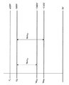
図2は、複数のトナーパッチ画像を含む画像の形成中の、受光体上の例示的な複数の電位レベルを示している。図2では、まず受光体10は、例えば−650ボルトの表面電位VLに帯電させられる。次に、受光体10は、画像信号によって変調された光で照射される。すると、露光領域電位Veは、例えば−160から−110ボルトまでの電位となる。次に、例えば−500ボルトの現像バイアス電圧が受光体に印加され、露光領域電位Veと現像バイアスVDとの電圧差Vemに従って、負に帯電されたトナーが現像ロールから受光体10の露光領域に引き付けられる。この電圧差Vemはコントラスト電位としても知られている。トナーパッチが形成され、上述したものと同様の電位関係を有する画像が形成される。Vemは、現像電圧と放電電圧との差を表す。
FIG. 2 illustrates exemplary potential levels on a photoreceptor during formation of an image including a plurality of toner patch images. In Figure 2, the
図3は、本発明のシステム及び方法による、トナー濃度較正リターンパッチレイアウトの例示的な一実施形態を示す。図3に示されている例示的な実施形態では、処理方向は右から左に移動する。受光体の左側のセグメント300は、受光体10上の最後の画像領域である。次のセグメント100は、受光体10上の画像間領域の始まりであり、受光体のバイアスレベルが0の領域であって、つまり、そこでは現像が生じない。次の画像間領域セグメント200はむき出しの受光体セグメントである。例えば赤外濃度計等の濃度計は、100%の反射率の読み取り値が得られるように較正される。画像間セグメント200は、現像されないむき出しの受光体パッチ201が得られるように光源が適用される受光体セグメントである。
FIG. 3 illustrates an exemplary embodiment of a toner density calibration return patch layout according to the systems and methods of the present invention. In the exemplary embodiment shown in FIG. 3, the processing direction moves from right to left. The
次の領域110では、受光体10に現像電位バイアス電圧が印加される。領域210では、100%領域被覆率連続階調グレーパッチ211が形成されるよう露光が行われる。露光バイアス電圧は相対的に低く、印加された現像電圧と、例えば−145〜−160ボルトの露光電圧との間に電圧差を生じる。Vemは、受光体に入射した露光光線に起因する、現像電圧Vdと放電電圧Veとの差である。高VemHiパッチのVem値はほぼ145〜160ボルトの間である。次の領域、即ち受光体の領域120では、受光体10に現像バイアス電圧が印加される。次に、領域220では、例えば−105〜−120ボルトの異なるバイアス電圧のパッチが露光される。Vemは、受光体に入射した露光光線に起因する、現像電圧Vdと放電電圧Veとの差である。低VemLoパッチのVem値はほぼ105〜120ボルトの間である。
In the
次の領域であるセグメント130では、現像バイアス電圧は印加されない。次の領域であるセグメント310では、画像間パッチサイクルは、例えば顧客の画像を露光及び現像する次のルーチンへの移行を開始する。所定のVem目標(例えば120ボルト及び160ボルト)が満たされていることを確実にするために、パッチのVeレベル、即ち放電電圧レベルが静電ボルトメータ33によって評価される。これらのグレーパッチは、一方がVemhigh(高)でありもう一方がVemlow(低)である2つの異なるVemレベルで生成される。次に、得られたパッチが濃度計によって評価され、読み取り結果が平均化されて、トナー濃度レベルの測定値が与えられる。Vem目標レベルは、所望の測定範囲の両極端における固有のパッチのトナー濃度応答を利用するように選択される。
In the next area, the
図3に示される低い方のVemパッチの反射率は、低いトナー濃度レベルでは横ばいであり、全測定範囲の中間域で、有用なトナー濃度応答の流れに入り始める。図3に示される高い方のVemパッチは、低いトナー濃度レベルでは有用な相対反射率の傾きで応答し、所望の測定範囲の中間域で、横ばいの飽和応答に入り始める。これらの2つのパッチの相対反射率を平均化することにより、より線形のトナー制御応答が得られ、これにより、拡大されたトナー濃度測定範囲が提供される。 The reflectivity of the lower Vem patch shown in FIG. 3 levels off at low toner density levels, and begins to flow into a useful toner density response stream in the middle of the full measurement range. The higher Vem patch shown in FIG. 3 responds with a useful relative reflectance slope at lower toner density levels and begins to enter a plateau saturation response in the middle of the desired measurement range. Averaging the relative reflectivity of these two patches results in a more linear toner control response, which provides an extended toner density measurement range.
図4は、x軸に沿ってトナー濃度を表示し、y軸に沿って受光体10上の100%領域被覆率の現像されたトナーパッチの相対反射率を表示した、トナー濃度感度曲線を示す。これらの曲線は、複数の異なるトナー濃度を用いて較正パッチを現像することによって形成される。例えば、図4に示されている較正曲線の例示的な実施形態では、トナー濃度を約3.5から約7まで変化させた(トナー濃度T/Dはトナー重量(グラム)を現像剤全体の重量で割った比率として定義される)。上の曲線は、HiVemパッチのトナー濃度vs相対反射率を示す。図4に示される実施形態の具体例では、上の較正曲線は、約155ボルトの異なる電圧Vemで形成された。下の曲線は、LoVemパッチのトナー濃度vs相対反射率を示す。図4に示される実施形態の具体例では、下の較正曲線は、約115ボルトの異なる電圧Vemで形成された。真ん中の較正曲線は、上下の較正曲線の平均を示す。上の較正曲線は、約5より低いトナー濃度で飽和する傾向がある。下の較正曲線は、約5より高いトナー濃度で飽和する傾向がある。しかし、真ん中の較正曲線、即ち、平均較正曲線は、約3.5〜7の全トナー濃度範囲を通して良好な傾きを有するように見える。従って、真ん中の較正曲線は、2つのトナーパッチの平均相対反射率とトナー濃度との間の予測可能且つ略線形の関係を与える。これにより、改良されたトナー濃度制御が得られる。なお、図4では、上下の各較正曲線を決定するために、7つの異なるトナー濃度の値を用いている。
FIG. 4 shows a toner density sensitivity curve displaying the toner density along the x-axis and the relative reflectance of a developed toner patch with 100% area coverage on the
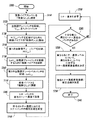
図5は、本発明によるトナー濃度センサ較正曲線を決定する方法の例示的な一実施形態を示すフローチャートである。図5に示されるように、この方法はステップS100で開始し、ステップS110に進み、そこで、現像バイアスが「現像なし」に調節される。次にステップS120で、第1のパッチである、現像されないクリア(何も無い)パッチが受光体上に画像形成される。このパッチは、較正対象のトナー濃度センサの較正に用いられる100%反射パッチである。次にステップS130で、現像バイアスがオンにされ、受光体上に相対的に高いVemのパッチを現像/記録可能なように調節される。次に、制御はステップS140に進む。 FIG. 5 is a flowchart illustrating an exemplary embodiment of a method for determining a toner concentration sensor calibration curve according to the present invention. As shown in FIG. 5, the method starts at step S100 and proceeds to step S110, where the developing bias is adjusted to "no development". Next, in step S120, an undeveloped clear (nothing) patch, which is the first patch, is image-formed on the photoreceptor. This patch is a 100% reflection patch used for calibrating the toner density sensor to be calibrated. Next, in step S130, the developing bias is turned on, and adjustment is made so that a relatively high Vem patch can be developed / recorded on the photoreceptor. Next, control proceeds to step S140.
ステップS140では、相対的に高いVemで、受光体上に100%領域被覆率グレー連続階調パッチが画像形成される。次にステップS150では、相対的に低いVemのパッチを現像/記録可能となるように、受光体10に現像電圧を印加するために、現像電圧が調節される。次にステップS160では、相対的に低いVemで、受光体上に100%領域被覆率グレーレベルパッチが露光される。次に、制御はステップS170に進む。
In step S140, a 100% area coverage gray continuous tone patch is imaged on the photoreceptor at a relatively high V em . Next, in step S150, the developing voltage is adjusted in order to apply a developing voltage to the
ステップS170では、現像バイアスが「現像なし」に調節される。次にステップS180では、トナーパッチが所与のトナー濃度で現像される。次にステップS190では、所与のトナー濃度で現像された現像済トナーパッチの相対反射が取得される。次に、処理はステップS200に進む。 In step S170, the developing bias is adjusted to “no development”. Next, in step S180, the toner patch is developed with a given toner density. Next, in step S190, the relative reflection of the developed toner patch developed with the given toner density is obtained. Next, the process proceeds to step S200.
ステップS200では、所望の数のベースとなるトナー濃度感度曲線を決定するのに十分な数の異なるトナー濃度で現像された十分な数のトナーパッチがあるか否かが決定される。否定された場合には、制御はステップS210に進み、そこで、プリントエンジンのトナー濃度が、前に用いた値と異なる値に変更される。次に、制御はステップS110にジャンプして戻る。 In step S200, it is determined whether there is a sufficient number of toner patches developed with a sufficient number of different toner densities to determine a desired number of base toner density sensitivity curves. If not, control proceeds to step S210, where the print engine toner density is changed to a value different from the previously used value. Next, control jumps back to step S110.
一方、十分な数のトナーパッチが現像されて検出された場合には、制御はステップS220に進む。ステップS220では、異なる各Vemレベルについて、異なる各トナー濃度レベルに対してその電圧レベルで現像されたトナーパッチから、較正曲線が決定される。次にステップS230では、複数の別個の較正曲線の少なくとも幾つかから、結合された較正曲線が決定される。次にステップS240で、この方法の処理が終了する。 On the other hand, if a sufficient number of toner patches have been developed and detected, control proceeds to step S220. In step S220, for each different Vem level, a calibration curve is determined from the toner patches developed at that voltage level for each different toner density level. Next, in step S230, a combined calibration curve is determined from at least some of the plurality of separate calibration curves. Next, in step S240, the processing of this method ends.
上述のように取得された結合較正曲線に基づき、コントローラ30は、トナー濃度、現像電圧、ジャンピングAC電圧(使用する場合)等のパラメータを変更してもよく、電子写真プリント装置1の出力を向上させるために、様々なファクタの中でも特に周囲温度及び相対湿度条件に基づいて、同様の調節を行ってもよい。本明細書に援用する米国特許第6,035,152号は、電子写真プリント装置1のこのようなプロセス制御用のシステム及び方法を開示している。
Based on the coupling calibration curve obtained as described above, the
この技術は、従来の装置より広いトナー濃度範囲にわたる感度を与え、制御されたトナー濃度の目標範囲からシステムがどれだけ乖離しているかについて、より正確な指標を与える。このシステムは、静電ボルトメータ(ESV)33及び赤外濃度計(IED)32、並びに、オプションとして水分/相対湿度センサ34及び温度センサ35を用いる。
This technique provides sensitivity over a wider range of toner densities than conventional devices, and provides a more accurate indication of how far the system deviates from a controlled target range of toner densities. The system uses an electrostatic voltmeter (ESV) 33 and an infrared densitometer (IED) 32, and optionally a moisture / relative humidity sensor 34 and a
帯電領域の電位は環境及び受光体の個体差に幾分影響されるので、現像剤の帯電量は湿度の変化及び現像剤の劣化に伴って変化する。例えば、現像材料が長時間(例えば24時間以上)にわたって用いられない場合には、現像材料粒子、即ちトナー及びキャリア粒子間の帯電が弱まり、湿度が高くなると一層弱まる。この正味の影響は、最初の数枚のコピーが期待よりも暗くなることであり、コピー品質が相対的に悪くなる。結果として、本発明によるシステム及び方法は、温度及び相対湿度のファクタをトナー濃度の制御の補助に用いる際の、温度及び相対湿度の検出にも備える。 Since the potential of the charged area is somewhat affected by the environment and individual differences of the photoreceptors, the amount of charge of the developer changes with changes in humidity and deterioration of the developer. For example, when the developing material is not used for a long time (for example, 24 hours or more), the charge between the developing material particles, that is, the toner and the carrier particles is weakened, and the charging is further weakened when the humidity is increased. The net effect is that the first few copies are darker than expected, and the copy quality is relatively poor. As a result, the systems and methods according to the present invention also provide for temperature and relative humidity detection when the temperature and relative humidity factors are used to assist in controlling toner concentration.
本発明によるシステム及び方法は、プリントシステムの構成要素の広い寛容度及び高画質を維持する能力を達成する。具体的には、本発明のシステム及び方法は、トナー濃度センサを、センサが最も感度の高いデータを与える2つの極端な現像電圧レベルで動作させることにより、トナー濃度センサを較正する。 The systems and methods according to the present invention achieve the ability to maintain wide latitude and high image quality of the components of the printing system. Specifically, the systems and methods of the present invention calibrate the toner concentration sensor by operating the toner concentration sensor at two extreme development voltage levels that provide the most sensitive data.
本発明によるシステム及び方法は、ゼログラフィ方式プリント装置のトナー濃度制御の画質設定と運転モードサイクルアウト後の評価との両方を達成するために用いられてもよい。 The system and method according to the present invention may be used to achieve both an image quality setting for toner density control and an evaluation after a running mode cycle out of a xerographic printing apparatus.
本明細書では、現時点で本発明の例示的な実施形態であると思われるものを示して説明したが、当業者は多くの変更及び変形に想到し得ることが認識されよう。従って、添付の特許請求の範囲では、本発明の真の精神及び範囲に含まれるそれらの変更及び変形の全てをカバーすることが意図される。 While this specification has shown and described what is presently considered to be exemplary embodiments of the present invention, it will be appreciated that many modifications and variations will occur to those skilled in the art. It is therefore intended in the appended claims to cover all such changes and modifications that fall within the true spirit and scope of the invention.
1 電子写真プリント装置
10 受光体(ベルト)
12 光導電面
30 コントローラ
31 エキスパートシステム
32 トナー領域被覆率センサ(濃度計)
33 静電ボルトメータ
34 水分/相対湿度センサ
35 温度センサ
1
12
33 Electrostatic voltmeter 34 Moisture /
Claims (2)
受光体上に、露光放電電圧と現像電圧との間の特定の相対的に大きい電圧差で、第1のパッチを画像形成する工程と、
露光放電電圧と相対的に小さい現像電圧との間の相対的により小さい電圧差で、第2のパッチを画像形成する工程と、
前記第1及び第2のパッチを第1のトナー濃度で現像する工程と、
前記画像形成工程を繰り返して得られた第1及び第2のパッチを、前記第1のトナー濃度とは異なるトナー濃度で現像する工程と、
前記複数の異なるトナー濃度における、現像された前記第1のパッチ及び前記第2のパッチの相対反射率の値を決定する工程と、
各トナー濃度の値に対する前記第1及び第2のパッチの前記相対反射率の値を結合し、前記プリントエンジンの平均トナー濃度感度を与える工程と、
を含む、トナー濃度センサの較正方法。 A method for calibrating a toner concentration sensor of a print engine having an exposure discharge voltage and a development voltage,
Imaging a first patch on the photoreceptor with a specific relatively large voltage difference between the exposure discharge voltage and the development voltage;
Imaging the second patch with a relatively smaller voltage difference between the exposure discharge voltage and the relatively smaller development voltage;
Developing the first and second patches with a first toner density;
Developing the first and second patches obtained by repeating the image forming step with a toner density different from the first toner density;
Determining a value of a relative reflectance of the developed first patch and the second patch at the plurality of different toner densities;
Combining the relative reflectance values of the first and second patches for each toner density value to provide an average toner density sensitivity of the print engine;
A calibration method for a toner concentration sensor, comprising:
受光体上に、少なくとも、露光放電電圧と現像電圧との間の相対的に大きい電圧差で第1の連続階調グレーパッチを画像形成し、且つ、露光放電電圧と現像電圧との間の相対的に小さい電圧差で第2のパッチを画像形成する画像形成器と、
前記少なくとも第1及び第2のパッチを所定の異なるトナー濃度で現像する現像装置と、
前記少なくとも第1及び第2のパッチの反射率を検出するセンサと、
所定のトナー濃度に対する結合反射率を決定するために、前記少なくとも第1及び第2のパッチの前記検出された反射率を結合する結合回路又は結合アプリケーションと、
を含み、
前記所定のトナー濃度が1つのトナー濃度範囲にわたって変更され、前記少なくとも第1及び第2のパッチが繰り返し画像形成され且つ前記トナー濃度範囲にわたる複数の異なるトナー濃度で現像され、前記センサが前記複数の異なるトナー濃度に対する前記第1及び第2のパッチの反射率を検出し、前記結合回路が前記複数の異なるトナー濃度に対する反射率を決定する、
トナー濃度センサの較正システム。 A calibration system for a print engine toner density sensor having an exposure discharge voltage and a development voltage, comprising:
Forming a first continuous tone gray patch on the photoreceptor with at least a relatively large voltage difference between the exposure discharge voltage and the development voltage; Forming an image of the second patch with a relatively small voltage difference;
A developing device for developing the at least first and second patches with predetermined different toner densities;
A sensor for detecting the reflectance of the at least first and second patches;
A coupling circuit or application that combines the detected reflectances of the at least first and second patches to determine a combined reflectance for a predetermined toner concentration;
Including
The predetermined toner density is changed over one toner density range; the at least first and second patches are repeatedly imaged and developed with a plurality of different toner densities over the toner density range; Detecting reflectances of the first and second patches for different toner densities, wherein the combining circuit determines the reflectances for the plurality of different toner densities;
Calibration system for toner concentration sensor.
Applications Claiming Priority (1)
| Application Number | Priority Date | Filing Date | Title |
|---|---|---|---|
| US10/248,390 US6792220B2 (en) | 2003-01-15 | 2003-01-15 | Dual density gray patch toner control |
Publications (1)
| Publication Number | Publication Date |
|---|---|
| JP2004220030A true JP2004220030A (en) | 2004-08-05 |
Family
ID=32592786
Family Applications (1)
| Application Number | Title | Priority Date | Filing Date |
|---|---|---|---|
| JP2004006166A Pending JP2004220030A (en) | 2003-01-15 | 2004-01-14 | Method and system for calibrating toner concentration sensor |
Country Status (4)
| Country | Link |
|---|---|
| US (1) | US6792220B2 (en) |
| EP (1) | EP1439431B1 (en) |
| JP (1) | JP2004220030A (en) |
| DE (1) | DE602004010554T2 (en) |
Cited By (1)
| Publication number | Priority date | Publication date | Assignee | Title |
|---|---|---|---|---|
| JP2009540387A (en) * | 2006-06-14 | 2009-11-19 | イーストマン コダック カンパニー | Method and system for maintaining print quality |
Families Citing this family (14)
| Publication number | Priority date | Publication date | Assignee | Title |
|---|---|---|---|---|
| CN100378600C (en) * | 2003-11-11 | 2008-04-02 | 三星电子株式会社 | Control method of image forming apparatus |
| US7259857B2 (en) | 2004-01-14 | 2007-08-21 | Xerox Corporation | Methods for automated uniformity assessment and modification of image non-uniformities |
| JP4236259B2 (en) * | 2004-03-08 | 2009-03-11 | キヤノン株式会社 | Recording device |
| US20050244175A1 (en) * | 2004-04-29 | 2005-11-03 | Dennis Abramsohn | Initiating a calibration procedure in a printing device |
| US7516040B2 (en) * | 2004-12-02 | 2009-04-07 | Xerox Corporation | System and method for automated detection of printing defects in an image output device |
| US7127187B2 (en) * | 2005-01-11 | 2006-10-24 | Xerox Corporation | Tone reproduction curve and developed mass per unit area control method and system |
| US7274887B2 (en) * | 2005-01-11 | 2007-09-25 | Xerox Corporation | System and method for setup of toner concentration target for a toner concentration sensor |
| US7158732B2 (en) * | 2005-01-11 | 2007-01-02 | Xerox Corporation | Method and system for using toner concentration as an active control actuator for TRC control |
| US7471420B2 (en) * | 2005-03-31 | 2008-12-30 | Xerox Corporation | Method of uniformity correction in an electrostatographic printer by using a second actuator |
| US7539427B2 (en) | 2006-06-14 | 2009-05-26 | Eastman Kodak Company | Print quality maintenance method and system |
| KR101265264B1 (en) * | 2006-07-31 | 2013-05-16 | 삼성전자주식회사 | Method and apparatus for estimating toner density using toner image, method and apparatus for supplying toner using thereof |
| JP5102082B2 (en) * | 2008-03-18 | 2012-12-19 | 株式会社リコー | Image forming apparatus |
| US20120201559A1 (en) * | 2009-10-30 | 2012-08-09 | Holland William D | Calibrated reflection densitometer |
| WO2016085560A1 (en) * | 2014-11-25 | 2016-06-02 | Cypress Semiconductor Corporation | Methods and sensors for multiphase scanning in the fingerprint and touch applications |
Family Cites Families (7)
| Publication number | Priority date | Publication date | Assignee | Title |
|---|---|---|---|---|
| US5559579A (en) * | 1994-09-29 | 1996-09-24 | Xerox Corporation | Closed-loop developability control in a xerographic copier or printer |
| JPH103186A (en) * | 1996-03-19 | 1998-01-06 | Xerox Corp | Electrostatic photographic printing machine, and monitoring/controlling method for electric parameter on image forming surface |
| US6029021A (en) * | 1996-12-20 | 2000-02-22 | Fuji Xerox Co., Ltd. | Image forming apparatus having an adaptive mode density control system |
| JP3426895B2 (en) * | 1997-01-30 | 2003-07-14 | シャープ株式会社 | Image quality compensation device for image forming apparatus |
| US6035152A (en) * | 1997-04-11 | 2000-03-07 | Xerox Corporation | Method for measurement of tone reproduction curve |
| JPH11167230A (en) * | 1997-12-04 | 1999-06-22 | Minolta Co Ltd | Image forming device, and method for adjusting image density thereof |
| US5895141A (en) * | 1998-04-06 | 1999-04-20 | Xerox Corporation | Sensorless TC control |
-
2003
- 2003-01-15 US US10/248,390 patent/US6792220B2/en not_active Expired - Fee Related
-
2004
- 2004-01-14 JP JP2004006166A patent/JP2004220030A/en active Pending
- 2004-01-14 EP EP04000657A patent/EP1439431B1/en not_active Expired - Lifetime
- 2004-01-14 DE DE602004010554T patent/DE602004010554T2/en not_active Expired - Lifetime
Cited By (1)
| Publication number | Priority date | Publication date | Assignee | Title |
|---|---|---|---|---|
| JP2009540387A (en) * | 2006-06-14 | 2009-11-19 | イーストマン コダック カンパニー | Method and system for maintaining print quality |
Also Published As
| Publication number | Publication date |
|---|---|
| EP1439431B1 (en) | 2007-12-12 |
| US20040136737A1 (en) | 2004-07-15 |
| US6792220B2 (en) | 2004-09-14 |
| DE602004010554T2 (en) | 2008-04-30 |
| DE602004010554D1 (en) | 2008-01-24 |
| EP1439431A1 (en) | 2004-07-21 |
Similar Documents
| Publication | Publication Date | Title |
|---|---|---|
| US5410388A (en) | Automatic compensation for toner concentration drift due to developer aging | |
| JPH09106120A (en) | Control method of development | |
| JP5550267B2 (en) | Image forming apparatus and method of controlling image forming apparatus | |
| JP2004220030A (en) | Method and system for calibrating toner concentration sensor | |
| JP4023573B2 (en) | Image forming apparatus | |
| JPH07175367A (en) | Image forming device | |
| US5797064A (en) | Pseudo photo induced discharged curve generator for xerographic setup | |
| US5937227A (en) | Uncoupled toner concentration and tribo control | |
| CA2200238C (en) | Photo induced discharge characteristics (pidc) controller | |
| US7313337B2 (en) | Method and apparatus for sensing and controlling residual mass on customer images | |
| JP3740850B2 (en) | Optical detection apparatus and method, and image density control apparatus | |
| US8712265B2 (en) | Image forming apparatus with an improved density adjustment unit | |
| JP3247812B2 (en) | Developer concentration detection method and developer concentration control method | |
| US5903800A (en) | Electrostatographic reproduction apparatus and method with improved densitometer | |
| EP1107070B1 (en) | Method and apparatus for adaptive black solid area estimation in a xerographic apparatus | |
| US7242876B2 (en) | Image forming apparatus with developer supply amount target value correcting feature using detected data relating to apparatus ambient environment and information relating to a sealed developer supply container environment | |
| JPH0915952A (en) | Developing device of electrophotographic printer | |
| JP2005018059A (en) | Method for measuring toner concentration | |
| US8005385B2 (en) | Electrophotographic system to enable direct sensing of toner quantity | |
| EP0871080B1 (en) | Background detection and compensation | |
| JP3659015B2 (en) | Density measuring apparatus and image forming apparatus using the same | |
| JP2001066837A (en) | Image forming device | |
| JP3360449B2 (en) | Image density control device | |
| JPH11194576A (en) | Method for forming density control patch, and image forming device using it | |
| JP3343298B2 (en) | Image forming device |
Legal Events
| Date | Code | Title | Description |
|---|---|---|---|
| A621 | Written request for application examination |
Free format text: JAPANESE INTERMEDIATE CODE: A621 Effective date: 20070112 |
|
| A977 | Report on retrieval |
Free format text: JAPANESE INTERMEDIATE CODE: A971007 Effective date: 20090603 |
|
| A131 | Notification of reasons for refusal |
Free format text: JAPANESE INTERMEDIATE CODE: A131 Effective date: 20090609 |
|
| A601 | Written request for extension of time |
Free format text: JAPANESE INTERMEDIATE CODE: A601 Effective date: 20090909 |
|
| A602 | Written permission of extension of time |
Free format text: JAPANESE INTERMEDIATE CODE: A602 Effective date: 20090914 |
|
| A521 | Written amendment |
Free format text: JAPANESE INTERMEDIATE CODE: A523 Effective date: 20091006 |
|
| A02 | Decision of refusal |
Free format text: JAPANESE INTERMEDIATE CODE: A02 Effective date: 20091201 |