US6740397B1 - Subseedlayers for magnetic recording media - Google Patents
Subseedlayers for magnetic recording media Download PDFInfo
- Publication number
- US6740397B1 US6740397B1 US09/847,434 US84743401A US6740397B1 US 6740397 B1 US6740397 B1 US 6740397B1 US 84743401 A US84743401 A US 84743401A US 6740397 B1 US6740397 B1 US 6740397B1
- Authority
- US
- United States
- Prior art keywords
- seedlayer
- magnetic recording
- recording medium
- subseedlayer
- magnetic
- Prior art date
- Legal status (The legal status is an assumption and is not a legal conclusion. Google has not performed a legal analysis and makes no representation as to the accuracy of the status listed.)
- Expired - Fee Related, expires
Links
Images


Classifications
-
- H—ELECTRICITY
- H01—ELECTRIC ELEMENTS
- H01F—MAGNETS; INDUCTANCES; TRANSFORMERS; SELECTION OF MATERIALS FOR THEIR MAGNETIC PROPERTIES
- H01F41/00—Apparatus or processes specially adapted for manufacturing or assembling magnets, inductances or transformers; Apparatus or processes specially adapted for manufacturing materials characterised by their magnetic properties
- H01F41/14—Apparatus or processes specially adapted for manufacturing or assembling magnets, inductances or transformers; Apparatus or processes specially adapted for manufacturing materials characterised by their magnetic properties for applying magnetic films to substrates
-
- G—PHYSICS
- G11—INFORMATION STORAGE
- G11B—INFORMATION STORAGE BASED ON RELATIVE MOVEMENT BETWEEN RECORD CARRIER AND TRANSDUCER
- G11B5/00—Recording by magnetisation or demagnetisation of a record carrier; Reproducing by magnetic means; Record carriers therefor
- G11B5/62—Record carriers characterised by the selection of the material
- G11B5/64—Record carriers characterised by the selection of the material comprising only the magnetic material without bonding agent
- G11B5/65—Record carriers characterised by the selection of the material comprising only the magnetic material without bonding agent characterised by its composition
- G11B5/657—Record carriers characterised by the selection of the material comprising only the magnetic material without bonding agent characterised by its composition containing inorganic, non-oxide compound of Si, N, P, B, H or C, e.g. in metal alloy or compound
-
- G—PHYSICS
- G11—INFORMATION STORAGE
- G11B—INFORMATION STORAGE BASED ON RELATIVE MOVEMENT BETWEEN RECORD CARRIER AND TRANSDUCER
- G11B5/00—Recording by magnetisation or demagnetisation of a record carrier; Reproducing by magnetic means; Record carriers therefor
- G11B5/62—Record carriers characterised by the selection of the material
- G11B5/73—Base layers, i.e. all non-magnetic layers lying under a lowermost magnetic recording layer, e.g. including any non-magnetic layer in between a first magnetic recording layer and either an underlying substrate or a soft magnetic underlayer
- G11B5/7368—Non-polymeric layer under the lowermost magnetic recording layer
- G11B5/7369—Two or more non-magnetic underlayers, e.g. seed layers or barrier layers
- G11B5/737—Physical structure of underlayer, e.g. texture
-
- G—PHYSICS
- G11—INFORMATION STORAGE
- G11B—INFORMATION STORAGE BASED ON RELATIVE MOVEMENT BETWEEN RECORD CARRIER AND TRANSDUCER
- G11B5/00—Recording by magnetisation or demagnetisation of a record carrier; Reproducing by magnetic means; Record carriers therefor
- G11B5/62—Record carriers characterised by the selection of the material
- G11B5/73—Base layers, i.e. all non-magnetic layers lying under a lowermost magnetic recording layer, e.g. including any non-magnetic layer in between a first magnetic recording layer and either an underlying substrate or a soft magnetic underlayer
- G11B5/7368—Non-polymeric layer under the lowermost magnetic recording layer
- G11B5/7379—Seed layer, e.g. at least one non-magnetic layer is specifically adapted as a seed or seeding layer
-
- G—PHYSICS
- G11—INFORMATION STORAGE
- G11B—INFORMATION STORAGE BASED ON RELATIVE MOVEMENT BETWEEN RECORD CARRIER AND TRANSDUCER
- G11B5/00—Recording by magnetisation or demagnetisation of a record carrier; Reproducing by magnetic means; Record carriers therefor
- G11B5/84—Processes or apparatus specially adapted for manufacturing record carriers
- G11B5/8404—Processes or apparatus specially adapted for manufacturing record carriers manufacturing base layers
-
- H—ELECTRICITY
- H01—ELECTRIC ELEMENTS
- H01F—MAGNETS; INDUCTANCES; TRANSFORMERS; SELECTION OF MATERIALS FOR THEIR MAGNETIC PROPERTIES
- H01F10/00—Thin magnetic films, e.g. of one-domain structure
- H01F10/26—Thin magnetic films, e.g. of one-domain structure characterised by the substrate or intermediate layers
- H01F10/30—Thin magnetic films, e.g. of one-domain structure characterised by the substrate or intermediate layers characterised by the composition of the intermediate layers, e.g. seed, buffer, template, diffusion preventing, cap layers
-
- Y—GENERAL TAGGING OF NEW TECHNOLOGICAL DEVELOPMENTS; GENERAL TAGGING OF CROSS-SECTIONAL TECHNOLOGIES SPANNING OVER SEVERAL SECTIONS OF THE IPC; TECHNICAL SUBJECTS COVERED BY FORMER USPC CROSS-REFERENCE ART COLLECTIONS [XRACs] AND DIGESTS
- Y10—TECHNICAL SUBJECTS COVERED BY FORMER USPC
- Y10T—TECHNICAL SUBJECTS COVERED BY FORMER US CLASSIFICATION
- Y10T428/00—Stock material or miscellaneous articles
- Y10T428/26—Web or sheet containing structurally defined element or component, the element or component having a specified physical dimension
- Y10T428/263—Coating layer not in excess of 5 mils thick or equivalent
- Y10T428/264—Up to 3 mils
- Y10T428/265—1 mil or less
Definitions
- This invention relates to magnetic recording media, such as thin film magnetic recording disks, and to a method of manufacturing the media.
- the invention has particular applicability to high areal density magnetic recording media having thin films for longitudinal magnetic recording media, and more particularly, to B2-structured underlayers for use with a cobalt or cobalt alloy based magnetic layer.
- Magnetic discs and disc drives provide quick access to vast amounts of stored information. Both flexible and rigid discs are available. Data on the discs is stored in circular tracks and divided into segments within the tracks. Disc drives typically employ one or more discs rotated on a central axis. A magnetic head is positioned over the disc surface to either access or add to the stored information. The heads for disc drives are mounted on a movable arm that carries the head in very close proximity to the disc over the various tracks and segments.
- FIG. 1 shows the schematic arrangement of a magnetic disk drive 10 using a rotary actuator.
- a disk or medium 11 is mounted on a spindle 12 and rotated at a predetermined speed.
- the rotary actuator comprises an arm 15 to which is coupled a suspension 14 .
- a magnetic head 13 is mounted at the distal end of the suspension 14 .
- the magnetic head 13 is brought into contact with the recording/reproduction surface of the disk 11 .
- the rotary actuator could have several suspensions and multiple magnetic heads to allow for simultaneous recording and reproduction on and from both surfaces of each medium.
- the arm 15 has a bobbin portion for holding a driving coil (not shown).
- a voice coil motor 19 as a kind of linear motor is provided to the other end of the arm 15 .
- the voice motor 19 has the driving coil wound on the bobbin portion of the arm 15 and a magnetic circuit (not shown).
- the magnetic circuit comprises a permanent magnet and a counter yoke. The magnetic circuit opposes the driving coil to sandwich it.
- the arm 15 is swingably supported by ball bearings (not shown) provided at the upper and lower portions of a pivot portion 17 .
- the ball bearings provided around the pivot portion 17 are held by a carriage portion (not shown).
- a magnetic head support mechanism is controlled by a positioning servo driving system.
- the positioning servo driving system comprises a feedback control circuit having a head position detection sensor (not shown), a power supply (not shown), and a controller (not shown).
- a signal is supplied from the controller to the respective power supplies based on the detection result of the position of the magnetic head 13 , the driving coil of the voice coil motor 19 and the piezoelectric element (not shown) of the head portion are driven.
- a longitudinal recording medium typically comprises a non-magnetic substrate 20 having sequentially deposited on each side thereof an underlayer 21 , 21 ′, such as chromium (Cr) or Cr-alloy, a magnetic layer 22 , 22 ′, typically comprising a cobalt (Co) -base alloy, and a protective overcoat 23 , 23 ′, typically containing carbon. Conventional practices also comprise bonding a lubricant topcoat (not shown) to the protective overcoat. Underlayer 21 , 21 ′, magnetic layer 22 , 22 ′, and protective overcoat 23 , 23 ′, are typically deposited by sputtering techniques.
- the Co-base alloy magnetic layer deposited by conventional techniques normally comprises polycrystallites epitaxially grown on the polycrystal Cr or Cr-alloy underlayer.
- a magnetic material is composed of a number of submicroscopic regions called domains.
- Each domain contains parallel atomic moments and is always magnetized to saturation, but the directions of magnetization of different domains are not necessarily parallel.
- adjacent domains may be oriented randomly in any number of several directions, called the directions of easy magnetization, which depend on the geometry of the crystal. The resultant effect of all these various directions of magnetization may be zero, as is the case with an unmagnetized specimen.
- the domains most nearly parallel to the direction of the applied field grow in size at the expense of the others. This is called boundary displacement of the domains or the domain growth.
- a further increase in magnetic field causes more domains to rotate and align parallel to the applied field. When the material reaches the point of saturation magnetization, no further domain growth would take place on increasing the strength of the magnetic field.
- a magnetic material is said to possess a uniaxial anisotropy when all domains are oriented in the same direction in the material. On the other extreme, a magnetic material is said to be isotropic when all domains are oriented randomly.
- Hc coercivity
- Mr remanent magnetization
- S* coercive squareness
- the Co alloy thin film should have uniform small grains with grain boundaries which can magnetically isolate neighboring grains. This kind of microstructure and crystallographic texture is normally achieved by manipulating the deposition process, by grooving the substrate surface, or most often by the proper use of an underlayer.
- the linear recording density can be increased by increasing the Hr of the magnetic recording medium, and by decreasing the medium noise, as by maintaining very fine magnetically non-coupled grains.
- Medium noise in thin films is a dominant factor restricting increased recording density of high-density magnetic hard disk drives, and is attributed primarily to inhomogeneous grain size and intergranular exchange coupling. Accordingly, in order to increase linear density, medium noise must be minimized by suitable microstructure control.
- Underlayers can strongly influence the crystallographic orientation, the grain size and chemical segregation at the Co alloy grain boundaries.
- in-plane orientation has heretofore been achieved by grain-to-grain epitaxial growth of the HCP Co alloy thin film on a body centered cubic (BCC) Cr underlayer.
- BCC body centered cubic
- the polycrystalline Co-based alloy thin film is deposited with its c-axis, the 0002 axis, either parallel to the film plane or with a large component of the c-axis in the film plane.
- Different Co/Cr epitaxial relationships prevail for different deposition processes.
- the Cr underlayer must be thicker than about 100 ⁇ .
- Cr-alloy underlayers comprise chromium (Cr), vanadium (V), titanium (Ti), tungsten (W) or molybdenum (Mo).
- Conventional magnetic layers are CoCrTa, CoCrPtB, CoCrPt, CoCrPtTaNb and CoNiCr.
- a conventional longitudinal recording disk medium is prepared by depositing multiple layers of metal films to make a composite film.
- the multiple layer typically comprises a non-magnetic substrate, one or more underlayers, a magnetic layer, and a protective carbon layer.
- a polycrystalline epitaxially grown cobalt-chromium (CoCr) alloy magnetic layer is deposited on a chromium or chromium-alloy underlayer.
- Conventional methods for manufacturing a longitudinal magnetic recording medium with a glass, glass-ceramic, Al or Al—NiP substrate comprise applying a seedlayer between the substrate and underlayer.
- a conventional seedlayer seeds the nucleation of a particular crystallographic texture of the underlayer.
- a seedlayer is the first deposited layer on the non-magnetic substrate. The role of this layer is to texture (alignment) the crystallographic orientation of the subsequent Cr-containing underlayer.
- the seedlayer, underlayer, and magnetic layer are conventionally sequentially sputter deposited on the substrate in an inert gas atmosphere, such as an atmosphere of argon.
- a conventional carbon overcoat is typically deposited in argon with nitrogen, hydrogen or ethylene.
- Conventional lubricant topcoats are typically about 20 ⁇ thick.
- the magnetic properties such as Hr, Mr, S* and SMNR, which are critical to the performance of a magnetic alloy film, depend primarily upon the microstructure of the magnetic layer which, in turn, is influenced by one or more underlying layers on which it is deposited.
- a magnetic recording medium comprising a surface oxidized NiAl seedlayer, and sequentially deposited thereon a Cr-containing underlayer, a CoCrTa intermediate layer and a CoCrPtTa magnetic layer.
- “Seedlayer Induced (002) Crystallographic Texture in NiAl Underlayers,” L.-L. Lee, D. E. Laughlin and D. N. Lambeth, J. AppL. Phys ., 79 (8), pp. 4902-4904 (1996) discloses a MgO seedlayer.
- the invention provides a magnetic recording medium for high areal recording density exhibiting low noise, high coercivity.
- One way of achieving this goal is to produce a magnetic recording medium having a subseedlayer that could alter the structure of the surface upon which a seedlayer is deposited.
- the seedlayer should then be capable of inducing the c axis of a hexagonal crystalline phase (HCP) of a layer above the seedlayer to line predominantly parallel to the magnetic film of the media.
- the magnetic recording medium of the invention could comprise a substrate, a subseedlayer comprising a Group VIb element, a seedlayer comprised of a material having a B2-ordered crystalline structure, and a magnetic layer preferably formed from a Co or Co alloy film.
- the substrate could be a disk or a tape.
- An underlayer could also be provided, which could comprise of a material having either an A2 structure or a B2- ordered crystalline structure disposed between the seedlayer and the magnetic layer.
- the A2 phase is preferably Cr or a Cr alloy, such as CrV.
- the B2 phase is selected from the group consisting of NiAl, AlCo, FeAl, FeTi, CoFe, CoTi, CoHf, CoZr, NiTi, CuBe, CuZn, AlMn, AlRe, AgMg, and Al 2 FeMn 2 , and is most preferably FeAl or NiAl.
- An embodiment of this invention is a magnetic recording medium, comprising a substrate, a subseedlayer comprising a Group VIb element, a seedlayer comprising a material comprising a B2 structure, and a magnetic layer, in this order.
- the subseedlayer could further comprise a Group Vb element.
- the seedlayer could further comprise a (112) laminar texture.
- a portion of the seedlayer could be oxidized and the medium could further comprise an underlayer comprising a Cr-containing material.
- the oxidized portion of the seedlayer could contain from about 0.0001 atomic percent oxygen to about 20 atomic percent oxygen, preferably, from about 0.01 atomic percent oxygen to about 0.9 atomic percent oxygen.
- the oxidized portion of the seedlayer could have a mean grain size diameter of 10 nm or less.
- the subseedlayer could be amorphous.
- the magnetic recording medium could further comprise an intermediate layer interposed between the magnetic layer and the underlayer.
- the subseedlayer could be between about 1 nm to 50 nm thick and it could comprise Ta and W or Ni and W; the seedlayer could comprise Ni and Al.
- Another embodiment of this invention is a method of manufacturing a magnetic recording medium, comprising depositing a subseedlayer on a substrate; depositing a seedlayer on the subseedlayer and depositing a magnetic layer on the seedlayer, wherein the subseedlayer comprises a Group VIb element and the seedlayer comprises a material comprising a B2 structure.
- Another embodiment of this invention is a magnetic recording medium, comprising a seedlayer comprising a material comprising a B2 structure and means for improving a (112) laminar texture of the seedlayer.
- means for improving a (112) laminar texture of the seedlayer is a layer such as a subseedlayer.
- FIG. 1 is a view of a magnetic disk drive.
- FIG. 2 is a schematic representation of the film structure in accordance with a magnetic recording medium of the prior art.
- FIG. 3 is a schematic representation of the film structure in accordance with an embodiment of this invention.
- FIG. 4 shows the coercivities and SMNR of NiAlOx ⁇ CrRuW ⁇ CoCrPtB films with various thicknesses of TaW subseedlayers on glass substrates.
- FIG. 5 shows coercivities of NiAlOx ⁇ CrRuW ⁇ CoCrPtB films of various magnetic layer thicknesses with and without 26 ⁇ TaW subseedlayers on glass substrates.
- FIG. 6 shows SMNR of NiAlOx ⁇ CrRuW ⁇ CoCrPtB films of various magnetic layer thicknesses with and without 26 ⁇ TaW subseedlayers on glass sub strates.
- FIG. 7 shows coercivities of NiAlOx ⁇ CrRuW ⁇ CoCrPtB films of various NiAlOx layer thicknesses with and without 26 ⁇ TaWOx subseedlayers on glass substrates.
- FIG. 8 shows SNMR of NiAlOx ⁇ CrRuW ⁇ CoCrPtB films of various NiAlOx layer thicknesses with and without 26 ⁇ TaWOx subseedlayers on glass substrates.
- FIG. 9 shows SMNR and coercivities of NiAlOx ⁇ CrRuW ⁇ CoCrPtB films of various TaWOx layer thicknesses on glass substrates.
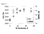
- FIG. 10 shows SMNR and coercivities of NiAlOx ⁇ CrRuW ⁇ CoCrPtB films with various thicknesses of W subseedlayers on glass substrates.
- FIG. 11 shows SMNR and coercivities of NiAlOx ⁇ CrRuW ⁇ CoCrPtB films with various thicknesses of NbW subseedlayers on glass substrates.
- the recording media of the invention may be a rigid magnetic disc rotatable about an axis that is incorporated into a disc drive shown in FIG. 1 .
- Disc drives such as this are standard equipment in the industry. See, Mee, C. D. and Daniel, E. D., MAGNETIC RECORDING, Vols. I-III (McGraw-Hill pub. 1987); F. Jorgenson, The Complete Handbook of Magnetic Recording, Chapter 16 (3rd. ed. 1988), and U.S. Pat. No. 5,062,021, the relevant disclosures of which are incorporated herein by reference.
- the magnetic recording media of the present invention may also be used with flexible magnetic discs or tapes using known flexible substrates.
- This invention provides magnetic recording media suitable for high areal recording density exhibiting high coercivity and high SMNR. This invention achieves such technological advantages by providing a subseedlayer below the seedlayer, over which an underlayer could be deposited.
- FIG. 3 shows a non-magnetic substrate 30 having sequentially deposited on each side thereof a W, NbW or TaW subseedlayer 31 , 31 ′, a NiAl or oxidized NiAl (NiAlOx) seedlayer 32 , 32 ′, a CrRuW underlayer 33 , 33 ′, a CoCrPtB magnetic layer 34 , 34 ′, and a protective overcoat 35 , 35 ′, typically containing carbon.
- the underlayer is to improve the crystallinity of the subsequent interface with the intermediate layer as well as to more closely assimilate the lattice parameters of the adjacent layers.
- a portion of the subseedlayer, the seedlayer and/or the underlayer could be oxidized by being sputter deposited with Ar and oxygen to promote a decrease in grain size.
- the term “a portion of” is defined herein to include all or part of a layer. Therefore, the entire layer, i.e., extending from one end of the layer to the opposite end of the layer may be in the oxidized form.
- first and second magnetic layers there may be first and second magnetic layers, and one or more interlayers disposed between the first magnetic layer and a second magnetic layer.
- the interlayer is preferably made of a non-magnetic body-centered cubic (BCC) material such as Cr and Cr alloy or a non-magnetic HCP material such as Ru and CoCrX, where X is B, Pt, Ru, Ta, Ti and Mo, and is about 0.1 nm to about 4 nm thick.
- BCC non-magnetic body-centered cubic
- HCP material such as Ru and CoCrX, where X is B, Pt, Ru, Ta, Ti and Mo, and is about 0.1 nm to about 4 nm thick.
- the second magnetic layer could be covered by an overlayer, an overcoat, and an organic lubricant.
- a seedlayer of about 1.0 nm to 50 nm thick may be disposed between the substrate and the underlayer to nucleate growth.
- the seedlayer is a B2-ordered crystalline structure with a (112) or (002) laminar texture sputter deposited on the subseedlayer, which is deposited on the substrate.
- the seedlayer of this embodiment could contain MgO that could result in a (002) laminar texture of the seedlayer.
- the B2-ordered crystalline structure of the seedlayer is most preferably NiAl. It is about 10-200 nm thick.
- the seedlayer may be FeAl or multiple layers alternating between a NiAl layer and a FeAl layer.
- a multiple layer having a first layer of NiAl and a second layer of FeAl, AlCo, FeTi, CoFe, CoTi, CoHf, CoZr, NiTi, CuBe, CuZn, AlMn, AlRe, AgMg or Al 2 FeMn 2 may be used.
- Various combinations of multiple layers wherein each layer is one of the B2-ordered crystalline phases could be employed as the seedlayer of the present invention.
- the underlayer could also be of a composition listed above.
- the subseedlayer is deposited, preferably by a physical sputtering method known in the art, on the non-magnetic substrate.
- an adhesion layer may be deposited on the substrate followed by the subseedlayer.
- a NiAl layer deposited on a NiP-plated aluminum substrate.
- the subseedlayer could then be deposited on the NiAl adhesion layer.
- the seedlayer is then deposited on the subseedlayer.
- one or more underlying layers are used between the seedlayer and the magnetic layer for longitudinal magnetic recording media.
- the underlying layers are chosen to obtain an underlayer exhibiting a (200)- or (112)-dominant crystallographic orientation to induce a (1120) or (1010)-dominant crystallographic orientation in the magnetic layer deposited and epitaxially grown thereon.
- the subseedlayer, seedlayer and/or underlayer could be oxidized by a reactive sputtering technique in an argon-oxygen environment.
- Suitable oxidizing atmospheres at a suitable temperature, e.g., about 100° C. to about 300° C., contain about 1 to about 100, preferably about 5 to about 80, volume percent of oxygen (O 2 ), the remainder being an inert gas, such as argon (Ar), in particular, about 1 to about 50 volume percent oxygen, such as about 20 percent by volume oxygen.
- the degree of oxidation can be such that the amount of oxygen in the top 50 ⁇ of the oxidized layer, after in situ sputter removal of the 40 ⁇ surface layer, is about 15 atomic percent to about 50 atomic percent, such as about 20 atomic percent to about 30 atomic percent.
- the amount of oxygen in the argon-oxygen environment is from 1% to 80% by volume oxygen, preferably 1% to 50% by volume oxygen, more preferably 1% to 25% by volume oxygen.
- the amount of oxygen in the oxidized portion of the seedlayer may vary from about 0.0001 atomic percent to 20 atomic percent, preferably from about 0.001 atomic percent to 10 atomic percent, and most preferably 0.01 atomic percent to 0.9 atomic percent.
- the magnetic layer is deposited with the magnetic easy axis, which would typically be the c axis in an HCP phase, of the magnetic layer substantially parallel to the plane of such magnetic layer.
- multiple magnetic layers are deposited, they are each about 5-60 nm thick.
- Embodiments of this invention include the use of any of the various magnetic alloys containing B, Cr and Co, such as CoCrB, CoCrPtB, CoCrNiB, CoCrNiPtB, CoCrNiTaB, CoCrNiNbB, CoCrPtTaB, CoCrPtNbB and CoCrPtTaNbB, and other combinations of B, Cr, Co, Pt, Ni, Ta and Nb, in the magnetic layer.
- An overlayer which is thought to prevent corrosion, may be provided adjacent to and preferably in contact with the magnetic layer.
- the overlayer is 0.1-5 nm thick and may be made of W, Ta, Zr, Ti, Y, Pt, Cr or any combination thereof.
- An overcoat may be provided external to the overlayer, so that the overlayer is positioned between the magnetic layer and the overcoat.
- the overcoat provides a mechanical wear layer and is typically 2.5-30 nm thick. It is preferably made of a ceramic material or diamond-like carbon, such as SiO 2 , SiC, CN, ZrO 2 or C.
- An organic lubricant may be disposed on the overcoat.
- the lubricant is generally 1 nm to 30 nm thick and is preferably a fluoro-chlorocarbon or a perfluoroether.
- Examples include CCl 2 FCClF 2 , CF 3 (CF 2 ) 4 CF 3 , CF 3 (CF 2 ) 5 CF 3 , CF 3 (CF 2 ) 10 CF 3 , and CF 3 (CF 2 ) 16 CF 3 .
- the substrates that may be used in the invention include glass, glass-ceramic, NiP/aluminum, metal alloys, plastic/polymer material, ceramic, glass-polymer, composite materials or other non-magnetic materials.
- the Cr-alloy underlayer may form a (112) surface orientation when deposited on a B2 structured seedlayer such as NiAl. Then, a magnetic layer having a substantially (1010) crystallographic orientation is deposited on the Cr-alloy underlayer.
- the lattice constant and the crystal plane of the seedlayer closely matches that of the Cr-alloy underlayer.
- the magnetic layer will grow in a close-packed hexagonal structure with a (1010) crystallographic orientation predominantly parallel to the film plane.
- the subsequently deposited magnetic layer exhibits a close-packed hexagonal structure with the magnetic easy axis, c-axis, lying predominantly in the film plane.
- the structure of the recording medium is the following: a glass or glass-ceramic substrate, W, NbW 40 or TaW 25 seedlayer on the substrate, an oxidized NiAl seedlayer, a CrRu 10 W 5 underlayer on the seedlayer, a CoCr 18 Pt 9.5 B 6 magnetic layer on the underlayer and a protective overcoat on the magnetic layer.
- a CoCr or CoCr-alloy intermediate layer is deposited on the underlayer.
- the structure of the intermediate layer is HCP.
- the CoCr-alloy could further contain Mo, Ta, Pt, Ru, Ti, B and Ni in the range of about 0 to about 40 atomic percent, more preferably, about 0.1 to about 7 atomic percent.
- a magnetic recording medium comprising a magnetic layer characterized by substantial directional magnetic isotropy exhibits significantly improved overwrite characteristics and significantly reduced magnetic property modulation, particularly reduced H c modulation in the circumferential direction.
- directional magnetic isotropy could decrease nonlinear noise behavior at high recording densities.
- the thickness of the subseedlayer is about 10 ⁇ to about 500 ⁇ , preferably between about 20-250 ⁇ , and most preferably about 25-40 ⁇ .
- the thickness of the B2 structure seedlayer is 200 ⁇ to about 1600 ⁇ , preferably between 300 ⁇ and 1200 ⁇ , and most preferably about 600 ⁇ .
- the thickness of the underlayer is 12 ⁇ to about 500 ⁇ , preferably between 15 ⁇ and 250 ⁇ , and most preferably about 25 ⁇ .
- the thickness of the magnetic layer is 50 ⁇ to about 300 ⁇ , preferably between 100 ⁇ and 225 ⁇ , and most preferably about 150-200 ⁇ .
- the thickness of the protective layer is 20 ⁇ to about 300 ⁇ , preferably between 30 ⁇ and 100 ⁇ , and most preferably about 50 ⁇ .
- the protective layer is made of hydrogenated carbon (CH x ).
- the magnetic recording medium has a remanent coercivity of about 2000 to about 10,000 Oersted, and an Mrt (product of remanance, Mr, and magnetic layer thickness, t) of about 0.2 to about 2.0 memu/cm 2 .
- the coercivity is about 2500 to about 9000 Oersted, more preferably in the range of about 3000 to about 6000 Oersted, and most preferably in the range of about 3350 to about 5000 Oersted.
- the Mrt is about 0.25 to about 1 memu/cm 2 , more preferably in the range of about 0.3 to about 0.7 memu/cm 2 , and most preferably in the range of about 0.3 to about 0.6 memu/cm 2 .
- subseedlayer is the layer sputtered immediately above the substrate. This layer alters the structure of the surface upon which the seedlayer is deposited. Hence, the subseedlayer can significantly affect the structure features, such as the distribution of grain size, grain shape and crystallographic texture, of the later deposited layers. Small grain size and a high degree of in-plane c-axis texture of the magnetic layer are beneficial to the recording properties of the longitudinal magnetic recording medium. The examples below illustrate the effect of the use of a subseedlayer in a recording medium.
- Tungsten alloys which can be sputtered to form films containing an amorphous material, nanocrystalline material and mixtures thereof, were chosen.
- Nanocrystalline material means fine crystals of less than 5 nm and could preferably be fine crystals of less than 2.5 nm.
- Such a subseedlayer is less likely to adversely affect the crystallographic texture of the seedlayer, such as the (112) laminar texture in NiAl and the (002) laminar texture in Cr or Cr alloys.
- W-Ta with 70 to 85 at % Ta
- W-Nb with 50 to 80 at % Nb
- subseedlayers of TaW and NbW can also significantly increase coercivity and SMNR of the media.
- the subseedlayer could be very thin ( ⁇ 20 ⁇ ) and still effective. Heater power could be reduced by about 50% without decreasing medium coercivity.
- 1 st layer (subseedlayer): W, NbW 40 or TaW 25
- seedlayer NiAl sputtered with Ar+O
- the 1 st , 2 nd and/or 3 rd layers were also sputtered with Ar+O gas to decrease grain size.
- the target offers the advantage of having less detrimental oxygen free in the sputter chamber, while reactive sputtering offers better control of oxidation level.
- oxygen-doped targets select an oxygen level between 0.01 and 0.9 atomic percent. Beyond this range, it might be intractable to maintain crystallographic integrity as the oxide component of the film may exceed the metallically bonded volume.
- the flow ratio should be set between Ar and O 2 such that oxygen makes up between 1% and 5% of the gas volume (pressure). The precise amount of incorporated oxygen is to be experimentally determined according to the alloy additions chosen; for more stable oxide-forming alloys, less oxygen would be needed in processing.
- an intermediate layer composed of identical portions of the magnetic layer alloy additions with sufficiently more Cr so as to render the material non-magnetic (>30 atomic percent) to a thickness of 35 ⁇ using a deposition rate of 25 ⁇ /s while maintaining a substrate bias of ⁇ 450 Volts and an argon pressure of 5 mTorr.
- This layer will allow the bcc-hcp transition to occur without sacrifice of anisotropy in the magnetic layer.
- step (1) and step (2) could be interchanged.
- the cleaning/polishing methods and the cleaning/polishing means that can employed are any one or more of the methods shown below.
- substrate surface initial condition roughness, waviness, substrate size, substrate shape and grain size
- polishing slurry size Al 2 O 3 , CeO 2 , SiO 2 , etc
- coolant inorganic and organic solutions with lubricant
- substrate surface initial condition roughness, waviness, substrate size, substrate shape and grain size
- the composition consists of a combination of different acids (e.g. nitric, sulfuric, hydrochloric, phosphoric, chromic, acetic) or organic solutions (e.g. methanol, glycerin, ethyldiglicol), also containing some added electropositive ions.
- acids e.g. nitric, sulfuric, hydrochloric, phosphoric, chromic, acetic
- organic solutions e.g. methanol, glycerin, ethyldiglicol
- the cathodic materials in general, the cathode surface should be many times larger than that of electropolished substrate. Different materials are used as cathodes depending on the applied electrolyte; and
- agitation which can eliminate the undesired concentration of the dissolved material at the substrate. Agitation can improve the supply of fresh electropolishing electrolyte to substrate surface. Agitation can prevent local heating and release gas bubbles from the polished surface to avoid pitting on the substrate surface
- CMP Chemical Mechanical Polishing
- FIG. 4 shows the coercivities and SMNR of NiAlOx ⁇ CrRuW ⁇ CoCrPtB films with various thickness of TaW subseedlayers on glass substrates.
- FIG. 4 shows that Hcr and SMNR increase from about 1,700 and 11 to about 3,500 and 15, respectively, when only a 20 ⁇ a subseedlayer of TaW is deposited between a glass substrate and an NiAl seedlayer.
- FIG. 5 shows coercivities of NiAlOx ⁇ CrRuW ⁇ CoCrPtB films of various magnetic layer thicknesses with and without 26 ⁇ TaW subseedlayers on glass substrates.
- FIG. 5 shows that the coercivities increase from 1,500-2,500 to 3,500-4,500 Oe by the use of TaW subseedlayers.
- FIG. 6 shows SMNR of NiAlOx ⁇ CrRuW ⁇ CoCrPtB films of various magnetic layer thicknesses with and without 26 ⁇ TaW subseedlayers on glass substrates.
- FIG. 6 shows that SMNR increases from 12-14 to 15-17 dB by the use of the TaW subseedlayer.
- FIG. 7 shows coercivities of NiAlOx ⁇ CrRuW ⁇ CoCrPtB films of various, NiAlOx layer thicknesses with and without 26 ⁇ TaWOx subseedlayers on glass substrates.
- FIG. 7 shows that the coercivities increase from 1,500-2,500 to 3,500-4,500 Oe by the use of TaW subseedlayers.
- FIG. 8 shows SNMR of NiAlOx ⁇ CrRuW ⁇ CoCrPtB films of various NiAlOx layer thicknesses with and without 26 ⁇ TaWOx subseedlayers on glass substrates.
- FIG. 8 shows that SMNR increases from 12-14 to 15-17 dB by the use of the TaW subseedlayer.
- FIG. 9 shows SMNR and coercivities of NiAlOx ⁇ CrRuW ⁇ CoCrPtB films of various TaWOx layer thicknesses on glass substrates.
- FIG. 10 shows SMNR and coercivities of NiAlOx ⁇ CrRuW ⁇ CoCrPtB films with various thicknesses of W subseedlayers on glass substrates.
- FIG. 11 shows SMNR and coercivities of NiAlOx ⁇ CrRuW ⁇ CoCrPtB films with various thicknesses of NbW subseedlayers on glass substrates.
- W-X alloy where X is Ta and/or Nb subseedlayers improves coercivity and SMNR of magnetic recording medium. Less than 100 ⁇ of the subseedlayer is sufficient to be effective.
- a useful range for Ta is 70 to 85 at % and for Nb 50 to 80 at %.
- Ternary W-X-Y alloy may also be used, where X and Y could be two different Group Vb elements.
Landscapes
- Engineering & Computer Science (AREA)
- Power Engineering (AREA)
- Manufacturing & Machinery (AREA)
- Metallurgy (AREA)
- Magnetic Record Carriers (AREA)
Abstract
Description
Claims (29)
Priority Applications (1)
| Application Number | Priority Date | Filing Date | Title |
|---|---|---|---|
| US09/847,434 US6740397B1 (en) | 2000-05-24 | 2001-05-03 | Subseedlayers for magnetic recording media |
Applications Claiming Priority (2)
| Application Number | Priority Date | Filing Date | Title |
|---|---|---|---|
| US20686700P | 2000-05-24 | 2000-05-24 | |
| US09/847,434 US6740397B1 (en) | 2000-05-24 | 2001-05-03 | Subseedlayers for magnetic recording media |
Publications (1)
| Publication Number | Publication Date |
|---|---|
| US6740397B1 true US6740397B1 (en) | 2004-05-25 |
Family
ID=32314325
Family Applications (1)
| Application Number | Title | Priority Date | Filing Date |
|---|---|---|---|
| US09/847,434 Expired - Fee Related US6740397B1 (en) | 2000-05-24 | 2001-05-03 | Subseedlayers for magnetic recording media |
Country Status (1)
| Country | Link |
|---|---|
| US (1) | US6740397B1 (en) |
Cited By (11)
| Publication number | Priority date | Publication date | Assignee | Title |
|---|---|---|---|---|
| US20050003561A1 (en) * | 2003-07-02 | 2005-01-06 | Drewes Joel A. | Method for production of MRAM elements |
| US6863993B1 (en) * | 2003-09-30 | 2005-03-08 | Hitachi Global Storage Technologies Netherlands, B.V. | Thin film media with a dual seed layer of RuAI/NiAIB |
| US20060110626A1 (en) * | 2004-11-24 | 2006-05-25 | Heraeus, Inc. | Carbon containing sputter target alloy compositions |
| US20070099032A1 (en) * | 2005-11-02 | 2007-05-03 | Heraeus, Inc., A Corporation Of The State Of Arizona | Deposition of enhanced seed layer using tantalum alloy based sputter target |
| US20070190364A1 (en) * | 2006-02-14 | 2007-08-16 | Heraeus, Inc. | Ruthenium alloy magnetic media and sputter targets |
| EP1930884A1 (en) * | 2006-12-05 | 2008-06-11 | Heraeus, Inc. | Ni-X, NI-Y, and NI-X-Y alloys with or without oxides as sputter targets for perpendicular magnetic recording |
| US20100007989A1 (en) * | 2008-07-14 | 2010-01-14 | Seagate Technology Llc | High density granular perpendicular recording media for mechanical reliability and corrosion resistance |
| US9034150B2 (en) | 2012-11-29 | 2015-05-19 | Seagate Technology Llc | Thin film with tuned anisotropy and magnetic moment |
| US9142226B2 (en) | 2012-06-29 | 2015-09-22 | Seagate Technology Llc | Thin film with tuned grain size |
| US9190080B1 (en) | 2007-08-16 | 2015-11-17 | Western Digital (Fremont), Llc | Method and system for providing a magnetic transducer having an improved hard bias seed layer |
| US9378760B2 (en) | 2014-07-31 | 2016-06-28 | Seagate Technology Llc | Data reader with tuned microstructure |
Citations (23)
| Publication number | Priority date | Publication date | Assignee | Title |
|---|---|---|---|---|
| JPS59178625A (en) | 1983-03-30 | 1984-10-09 | Hitachi Ltd | Disk substrate |
| US4828905A (en) | 1986-06-12 | 1989-05-09 | Sumitomo Special Metals Co., Ltd. | Magnetic recording medium |
| JPH05109039A (en) | 1991-09-18 | 1993-04-30 | Hitachi Metals Ltd | Magnetic recording medium |
| US5496606A (en) | 1990-11-30 | 1996-03-05 | Victor Company Of Japan, Ltd. | Magnetic recording medium |
| US5650889A (en) | 1994-02-07 | 1997-07-22 | Hitachi, Ltd. | Magnetic recording medium containing heavy rare gas atoms, and a magnetic transducing system using the medium |
| US5693426A (en) * | 1994-09-29 | 1997-12-02 | Carnegie Mellon University | Magnetic recording medium with B2 structured underlayer and a cobalt-based magnetic layer |
| US5700593A (en) | 1993-06-23 | 1997-12-23 | Kubota Corporation | Metal thin film magnetic recording medium and manufacturing method thereof |
| US5733370A (en) | 1996-01-16 | 1998-03-31 | Seagate Technology, Inc. | Method of manufacturing a bicrystal cluster magnetic recording medium |
| US5789090A (en) | 1996-02-05 | 1998-08-04 | Stormedia, Inc. | Metallic thin-film magnetic recording media |
| US5789056A (en) | 1997-01-30 | 1998-08-04 | International Business Machines Corporation | Thin film magnetic disk with chromium-titanium seed layer |
| US5800931A (en) | 1994-09-29 | 1998-09-01 | Carnegie Mellon University | Magnetic recording medium with a MgO sputter deposited seed layer |
| US5846648A (en) * | 1994-01-28 | 1998-12-08 | Komag, Inc. | Magnetic alloy having a structured nucleation layer and method for manufacturing same |
| US5858566A (en) | 1995-10-23 | 1999-01-12 | Seagate Technology, Inc. | Seeded underlayer in magnetic thin films |
| US5980997A (en) * | 1996-06-03 | 1999-11-09 | Komag, Incorporated | Method for preparing a substrate for a magnetic disk |
| US5993956A (en) * | 1997-04-22 | 1999-11-30 | Carnegie Mellon University | Manganese containing layer for magnetic recording media |
| US6010795A (en) | 1997-02-26 | 2000-01-04 | Seagate Technology, Inc. | Magnetic recording medium comprising a nickel aluminum or iron aluminum underlayer and chromium containing intermediate layer each having (200) dominant crystalographic orientation |
| US6077586A (en) | 1997-07-15 | 2000-06-20 | International Business Machines Corporation | Laminated thin film disk for longitudinal recording |
| US6139981A (en) | 1997-10-23 | 2000-10-31 | Seagate Technology, Inc. | Magnetic thin film medium with adhesion enhancement layer |
| US6139951A (en) * | 1997-12-12 | 2000-10-31 | Seagate Technology Llc | Magnetic recording medium with low temperature seedlayer for high signal-to-noise ratio |
| US6143388A (en) | 1997-11-24 | 2000-11-07 | International Business Machines Corporation | Thin film disk with onset layer |
| US6150015A (en) * | 1997-12-04 | 2000-11-21 | Komag, Incorporated | Ultra-thin nucleation layer for magnetic thin film media and the method for manufacturing the same |
| US6309765B1 (en) * | 1996-03-25 | 2001-10-30 | Asahi Komag Co., Ltd. | Magnetic recording medium and process for its production |
| US6346339B1 (en) * | 1998-09-30 | 2002-02-12 | Seagate Technology Llc | Magnetic recording media with a nialox sub-seedlayer |
-
2001
- 2001-05-03 US US09/847,434 patent/US6740397B1/en not_active Expired - Fee Related
Patent Citations (23)
| Publication number | Priority date | Publication date | Assignee | Title |
|---|---|---|---|---|
| JPS59178625A (en) | 1983-03-30 | 1984-10-09 | Hitachi Ltd | Disk substrate |
| US4828905A (en) | 1986-06-12 | 1989-05-09 | Sumitomo Special Metals Co., Ltd. | Magnetic recording medium |
| US5496606A (en) | 1990-11-30 | 1996-03-05 | Victor Company Of Japan, Ltd. | Magnetic recording medium |
| JPH05109039A (en) | 1991-09-18 | 1993-04-30 | Hitachi Metals Ltd | Magnetic recording medium |
| US5700593A (en) | 1993-06-23 | 1997-12-23 | Kubota Corporation | Metal thin film magnetic recording medium and manufacturing method thereof |
| US5846648A (en) * | 1994-01-28 | 1998-12-08 | Komag, Inc. | Magnetic alloy having a structured nucleation layer and method for manufacturing same |
| US5650889A (en) | 1994-02-07 | 1997-07-22 | Hitachi, Ltd. | Magnetic recording medium containing heavy rare gas atoms, and a magnetic transducing system using the medium |
| US5800931A (en) | 1994-09-29 | 1998-09-01 | Carnegie Mellon University | Magnetic recording medium with a MgO sputter deposited seed layer |
| US5693426A (en) * | 1994-09-29 | 1997-12-02 | Carnegie Mellon University | Magnetic recording medium with B2 structured underlayer and a cobalt-based magnetic layer |
| US5858566A (en) | 1995-10-23 | 1999-01-12 | Seagate Technology, Inc. | Seeded underlayer in magnetic thin films |
| US5733370A (en) | 1996-01-16 | 1998-03-31 | Seagate Technology, Inc. | Method of manufacturing a bicrystal cluster magnetic recording medium |
| US5789090A (en) | 1996-02-05 | 1998-08-04 | Stormedia, Inc. | Metallic thin-film magnetic recording media |
| US6309765B1 (en) * | 1996-03-25 | 2001-10-30 | Asahi Komag Co., Ltd. | Magnetic recording medium and process for its production |
| US5980997A (en) * | 1996-06-03 | 1999-11-09 | Komag, Incorporated | Method for preparing a substrate for a magnetic disk |
| US5789056A (en) | 1997-01-30 | 1998-08-04 | International Business Machines Corporation | Thin film magnetic disk with chromium-titanium seed layer |
| US6010795A (en) | 1997-02-26 | 2000-01-04 | Seagate Technology, Inc. | Magnetic recording medium comprising a nickel aluminum or iron aluminum underlayer and chromium containing intermediate layer each having (200) dominant crystalographic orientation |
| US5993956A (en) * | 1997-04-22 | 1999-11-30 | Carnegie Mellon University | Manganese containing layer for magnetic recording media |
| US6077586A (en) | 1997-07-15 | 2000-06-20 | International Business Machines Corporation | Laminated thin film disk for longitudinal recording |
| US6139981A (en) | 1997-10-23 | 2000-10-31 | Seagate Technology, Inc. | Magnetic thin film medium with adhesion enhancement layer |
| US6143388A (en) | 1997-11-24 | 2000-11-07 | International Business Machines Corporation | Thin film disk with onset layer |
| US6150015A (en) * | 1997-12-04 | 2000-11-21 | Komag, Incorporated | Ultra-thin nucleation layer for magnetic thin film media and the method for manufacturing the same |
| US6139951A (en) * | 1997-12-12 | 2000-10-31 | Seagate Technology Llc | Magnetic recording medium with low temperature seedlayer for high signal-to-noise ratio |
| US6346339B1 (en) * | 1998-09-30 | 2002-02-12 | Seagate Technology Llc | Magnetic recording media with a nialox sub-seedlayer |
Non-Patent Citations (5)
| Title |
|---|
| "Effects of Cr Intermediate Layers on CoCrPT Thin Film Media on NiAl underlayers," Li-Lien et al. IEEE Transactions on Magnetics, vol. 31, No. 6, Nov. 1995, pp. 2728-2730.* * |
| "Magnetic Properties and Noise Characteristics of High Coercivity CoCrPTB/Cr Media," Paik et al. IEEE Transactions on Magnetics, vol. 28, #5, Sep. 1992, pp. 3084-3086.* * |
| H. Kataoka et al., "Magnetic and recording characteristics of Cr, Ta, W and Zr pre-coated glass disks", IEEE Transactions on Magnetics, vol. 31, No. 6, pp. 2734-2736, Nov. 1995. |
| L. Lee et al., "FeAl underlayers for CoCrPt thin film longitudinal media", J. Appl. Phys. 81 (8), pp. 4366-4368, Apr. 15, 1997. |
| L. Lee et al., "Seed layer induced (002) crystallographic texture in NiAl underlayers", J. Appl. Phys. 79 (8), pp 4902-4904, Apr. 15, 1996. |
Cited By (20)
| Publication number | Priority date | Publication date | Assignee | Title |
|---|---|---|---|---|
| US7470552B2 (en) | 2003-07-02 | 2008-12-30 | Micron Technology, Inc. | Method for production of MRAM elements |
| US7884405B2 (en) | 2003-07-02 | 2011-02-08 | Micron Technology, Inc. | Method for production of MRAM elements |
| US20050003561A1 (en) * | 2003-07-02 | 2005-01-06 | Drewes Joel A. | Method for production of MRAM elements |
| US20090080240A1 (en) * | 2003-07-02 | 2009-03-26 | Drewes Joel A | Method for production of mram elements |
| US7189583B2 (en) * | 2003-07-02 | 2007-03-13 | Micron Technology, Inc. | Method for production of MRAM elements |
| US20050069730A1 (en) * | 2003-09-30 | 2005-03-31 | Doerner Mary Frances | Thin film media with a dual seed layer of rual/nialb |
| US6863993B1 (en) * | 2003-09-30 | 2005-03-08 | Hitachi Global Storage Technologies Netherlands, B.V. | Thin film media with a dual seed layer of RuAI/NiAIB |
| US20060110626A1 (en) * | 2004-11-24 | 2006-05-25 | Heraeus, Inc. | Carbon containing sputter target alloy compositions |
| EP1662018A3 (en) * | 2004-11-24 | 2006-11-08 | Heraeus, Inc. | Carbon containing sputter target alloy compositions |
| US20070099032A1 (en) * | 2005-11-02 | 2007-05-03 | Heraeus, Inc., A Corporation Of The State Of Arizona | Deposition of enhanced seed layer using tantalum alloy based sputter target |
| EP1783748A1 (en) * | 2005-11-02 | 2007-05-09 | Heraeus, Inc. | Deposition of enhanced seed layer using tantalum alloy based sputter target |
| US20070190364A1 (en) * | 2006-02-14 | 2007-08-16 | Heraeus, Inc. | Ruthenium alloy magnetic media and sputter targets |
| EP1930884A1 (en) * | 2006-12-05 | 2008-06-11 | Heraeus, Inc. | Ni-X, NI-Y, and NI-X-Y alloys with or without oxides as sputter targets for perpendicular magnetic recording |
| US9190080B1 (en) | 2007-08-16 | 2015-11-17 | Western Digital (Fremont), Llc | Method and system for providing a magnetic transducer having an improved hard bias seed layer |
| US20100007989A1 (en) * | 2008-07-14 | 2010-01-14 | Seagate Technology Llc | High density granular perpendicular recording media for mechanical reliability and corrosion resistance |
| US8993073B2 (en) * | 2008-07-14 | 2015-03-31 | Seagate Technology Llc | Applying bias voltage during formation of granular recording media |
| US9418693B2 (en) | 2008-07-14 | 2016-08-16 | Seagate Technology Llc | High density granular perpendicular recording media for mechanical reliability and corrosion resistance |
| US9142226B2 (en) | 2012-06-29 | 2015-09-22 | Seagate Technology Llc | Thin film with tuned grain size |
| US9034150B2 (en) | 2012-11-29 | 2015-05-19 | Seagate Technology Llc | Thin film with tuned anisotropy and magnetic moment |
| US9378760B2 (en) | 2014-07-31 | 2016-06-28 | Seagate Technology Llc | Data reader with tuned microstructure |
Similar Documents
| Publication | Publication Date | Title |
|---|---|---|
| US7851014B2 (en) | Tilted recording media with L10 magnetic layer | |
| US7235314B2 (en) | Inter layers for perpendicular recording media | |
| US6607842B2 (en) | Containing an AITa or AITi pre-seed layer, a CoCr onset layer and a CoCrPtB magnetic layer | |
| US6524730B1 (en) | NiFe-containing soft magnetic layer design for multilayer media | |
| US20090042062A1 (en) | Interlayer design for magnetic media | |
| US6403241B1 (en) | CoCrPtB medium with a 1010 crystallographic orientation | |
| US6740397B1 (en) | Subseedlayers for magnetic recording media | |
| JP2001344740A (en) | Magnetic recording medium and magnetic storage device | |
| US6914749B2 (en) | Magnetic anisotropy of soft-underlayer induced by magnetron field | |
| US6759149B1 (en) | Laminated medium with antiferromagnetic stabilization layers | |
| US6936353B1 (en) | Tilted recording medium design with (101-2) orientation | |
| US7919201B2 (en) | Method of making a multilayered magnetic structure | |
| US6872478B2 (en) | Magnetic thin film media with a pre-seed layer of CrTiAl | |
| JP5019955B2 (en) | Magnetic recording medium, manufacturing method thereof, and magnetic recording / reproducing apparatus | |
| US6787251B1 (en) | Recording medium with a varying composition underlayer | |
| US7521136B1 (en) | Coupling enhancement for medium with anti-ferromagnetic coupling | |
| US7314675B1 (en) | Magnetic media with high Ms magnetic layer | |
| JP2001189005A (en) | Magnetic recording medium, method of manufacturing the same, and magnetic storage device | |
| US6908689B1 (en) | Ruthenium-aluminum underlayer for magnetic recording media | |
| JP3663289B2 (en) | Magnetic recording medium and magnetic storage device | |
| JP4782047B2 (en) | Perpendicular magnetic recording medium and magnetic recording / reproducing apparatus | |
| US6849326B1 (en) | Niobium alloy seedlayer for magnetic recording media | |
| US7393601B1 (en) | Weak antiferromagnetically coupled media with a five element magnetic alloy and a low moment stabilizing layer | |
| US6756136B1 (en) | Chromium-alloy seedlayers for recording media | |
| JP3052406B2 (en) | Magnetic recording medium and magnetic storage device |
Legal Events
| Date | Code | Title | Description |
|---|---|---|---|
| AS | Assignment |
Owner name: SEAGATE TECHNOLOGY, LLC, CALIFORNIA Free format text: ASSIGNMENT OF ASSIGNORS INTEREST;ASSIGNOR:LEE, LI-LIEN;REEL/FRAME:011784/0864 Effective date: 20010501 |
|
| AS | Assignment |
Owner name: SEAGATE TECHNOLOGY LLC, CALIFORNIA Free format text: CORRECTIVE ASSIGNMENT TO CORRECT THE ASSIGNEE'S NAME PREVIOUSLY RECORDED ON REEL 011784, FRAME 0864;ASSIGNOR:LEE, LI-LIEN;REEL/FRAME:012599/0074 Effective date: 20010501 |
|
| AS | Assignment |
Owner name: JPMORGAN CHASE BANK, AS COLLATERAL AGENT, NEW YORK Free format text: SECURITY AGREEMENT;ASSIGNOR:SEAGATE TECHNOLOGY LLC;REEL/FRAME:013177/0001 Effective date: 20020513 Owner name: JPMORGAN CHASE BANK, AS COLLATERAL AGENT,NEW YORK Free format text: SECURITY AGREEMENT;ASSIGNOR:SEAGATE TECHNOLOGY LLC;REEL/FRAME:013177/0001 Effective date: 20020513 |
|
| AS | Assignment |
Owner name: SEAGATE TECHNOLOGY LLC, CALIFORNIA Free format text: RELEASE OF SECURITY INTERESTS IN PATENT RIGHTS;ASSIGNOR:JPMORGAN CHASE BANK, N.A. (FORMERLY KNOWN AS THE CHASE MANHATTAN BANK AND JPMORGAN CHASE BANK), AS ADMINISTRATIVE AGENT;REEL/FRAME:016958/0607 Effective date: 20051130 |
|
| FPAY | Fee payment |
Year of fee payment: 4 |
|
| REMI | Maintenance fee reminder mailed | ||
| AS | Assignment |
Owner name: WELLS FARGO BANK, NATIONAL ASSOCIATION, AS COLLATERAL AGENT AND SECOND PRIORITY REPRESENTATIVE, CALIFORNIA Free format text: SECURITY AGREEMENT;ASSIGNORS:MAXTOR CORPORATION;SEAGATE TECHNOLOGY LLC;SEAGATE TECHNOLOGY INTERNATIONAL;REEL/FRAME:022757/0017 Effective date: 20090507 Owner name: JPMORGAN CHASE BANK, N.A., AS ADMINISTRATIVE AGENT AND FIRST PRIORITY REPRESENTATIVE, NEW YORK Free format text: SECURITY AGREEMENT;ASSIGNORS:MAXTOR CORPORATION;SEAGATE TECHNOLOGY LLC;SEAGATE TECHNOLOGY INTERNATIONAL;REEL/FRAME:022757/0017 Effective date: 20090507 Owner name: JPMORGAN CHASE BANK, N.A., AS ADMINISTRATIVE AGENT Free format text: SECURITY AGREEMENT;ASSIGNORS:MAXTOR CORPORATION;SEAGATE TECHNOLOGY LLC;SEAGATE TECHNOLOGY INTERNATIONAL;REEL/FRAME:022757/0017 Effective date: 20090507 Owner name: WELLS FARGO BANK, NATIONAL ASSOCIATION, AS COLLATE Free format text: SECURITY AGREEMENT;ASSIGNORS:MAXTOR CORPORATION;SEAGATE TECHNOLOGY LLC;SEAGATE TECHNOLOGY INTERNATIONAL;REEL/FRAME:022757/0017 Effective date: 20090507 |
|
| AS | Assignment |
Owner name: MAXTOR CORPORATION, CALIFORNIA Free format text: RELEASE;ASSIGNOR:JPMORGAN CHASE BANK, N.A., AS ADMINISTRATIVE AGENT;REEL/FRAME:025662/0001 Effective date: 20110114 Owner name: SEAGATE TECHNOLOGY HDD HOLDINGS, CALIFORNIA Free format text: RELEASE;ASSIGNOR:JPMORGAN CHASE BANK, N.A., AS ADMINISTRATIVE AGENT;REEL/FRAME:025662/0001 Effective date: 20110114 Owner name: SEAGATE TECHNOLOGY INTERNATIONAL, CALIFORNIA Free format text: RELEASE;ASSIGNOR:JPMORGAN CHASE BANK, N.A., AS ADMINISTRATIVE AGENT;REEL/FRAME:025662/0001 Effective date: 20110114 Owner name: SEAGATE TECHNOLOGY LLC, CALIFORNIA Free format text: RELEASE;ASSIGNOR:JPMORGAN CHASE BANK, N.A., AS ADMINISTRATIVE AGENT;REEL/FRAME:025662/0001 Effective date: 20110114 |
|
| AS | Assignment |
Owner name: THE BANK OF NOVA SCOTIA, AS ADMINISTRATIVE AGENT, CANADA Free format text: SECURITY AGREEMENT;ASSIGNOR:SEAGATE TECHNOLOGY LLC;REEL/FRAME:026010/0350 Effective date: 20110118 Owner name: THE BANK OF NOVA SCOTIA, AS ADMINISTRATIVE AGENT, Free format text: SECURITY AGREEMENT;ASSIGNOR:SEAGATE TECHNOLOGY LLC;REEL/FRAME:026010/0350 Effective date: 20110118 |
|
| FPAY | Fee payment |
Year of fee payment: 8 |
|
| AS | Assignment |
Owner name: SEAGATE TECHNOLOGY US HOLDINGS, INC., CALIFORNIA Free format text: TERMINATION AND RELEASE OF SECURITY INTEREST IN PATENT RIGHTS;ASSIGNOR:WELLS FARGO BANK, NATIONAL ASSOCIATION, AS COLLATERAL AGENT AND SECOND PRIORITY REPRESENTATIVE;REEL/FRAME:030833/0001 Effective date: 20130312 Owner name: SEAGATE TECHNOLOGY LLC, CALIFORNIA Free format text: TERMINATION AND RELEASE OF SECURITY INTEREST IN PATENT RIGHTS;ASSIGNOR:WELLS FARGO BANK, NATIONAL ASSOCIATION, AS COLLATERAL AGENT AND SECOND PRIORITY REPRESENTATIVE;REEL/FRAME:030833/0001 Effective date: 20130312 Owner name: SEAGATE TECHNOLOGY INTERNATIONAL, CAYMAN ISLANDS Free format text: TERMINATION AND RELEASE OF SECURITY INTEREST IN PATENT RIGHTS;ASSIGNOR:WELLS FARGO BANK, NATIONAL ASSOCIATION, AS COLLATERAL AGENT AND SECOND PRIORITY REPRESENTATIVE;REEL/FRAME:030833/0001 Effective date: 20130312 Owner name: EVAULT INC. (F/K/A I365 INC.), CALIFORNIA Free format text: TERMINATION AND RELEASE OF SECURITY INTEREST IN PATENT RIGHTS;ASSIGNOR:WELLS FARGO BANK, NATIONAL ASSOCIATION, AS COLLATERAL AGENT AND SECOND PRIORITY REPRESENTATIVE;REEL/FRAME:030833/0001 Effective date: 20130312 |
|
| REMI | Maintenance fee reminder mailed | ||
| LAPS | Lapse for failure to pay maintenance fees | ||
| STCH | Information on status: patent discontinuation |
Free format text: PATENT EXPIRED DUE TO NONPAYMENT OF MAINTENANCE FEES UNDER 37 CFR 1.362 |
|
| STCH | Information on status: patent discontinuation |
Free format text: PATENT EXPIRED DUE TO NONPAYMENT OF MAINTENANCE FEES UNDER 37 CFR 1.362 |
|
| FP | Lapsed due to failure to pay maintenance fee |
Effective date: 20160525 |
|
| AS | Assignment |
Owner name: SEAGATE TECHNOLOGY PUBLIC LIMITED COMPANY, CALIFORNIA Free format text: RELEASE BY SECURED PARTY;ASSIGNOR:THE BANK OF NOVA SCOTIA;REEL/FRAME:072193/0001 Effective date: 20250303 Owner name: SEAGATE TECHNOLOGY, CALIFORNIA Free format text: RELEASE BY SECURED PARTY;ASSIGNOR:THE BANK OF NOVA SCOTIA;REEL/FRAME:072193/0001 Effective date: 20250303 Owner name: SEAGATE TECHNOLOGY HDD HOLDINGS, CALIFORNIA Free format text: RELEASE BY SECURED PARTY;ASSIGNOR:THE BANK OF NOVA SCOTIA;REEL/FRAME:072193/0001 Effective date: 20250303 Owner name: I365 INC., CALIFORNIA Free format text: RELEASE BY SECURED PARTY;ASSIGNOR:THE BANK OF NOVA SCOTIA;REEL/FRAME:072193/0001 Effective date: 20250303 Owner name: SEAGATE TECHNOLOGY LLC, CALIFORNIA Free format text: RELEASE BY SECURED PARTY;ASSIGNOR:THE BANK OF NOVA SCOTIA;REEL/FRAME:072193/0001 Effective date: 20250303 Owner name: SEAGATE TECHNOLOGY INTERNATIONAL, CAYMAN ISLANDS Free format text: RELEASE BY SECURED PARTY;ASSIGNOR:THE BANK OF NOVA SCOTIA;REEL/FRAME:072193/0001 Effective date: 20250303 Owner name: SEAGATE HDD CAYMAN, CAYMAN ISLANDS Free format text: RELEASE BY SECURED PARTY;ASSIGNOR:THE BANK OF NOVA SCOTIA;REEL/FRAME:072193/0001 Effective date: 20250303 Owner name: SEAGATE TECHNOLOGY (US) HOLDINGS, INC., CALIFORNIA Free format text: RELEASE BY SECURED PARTY;ASSIGNOR:THE BANK OF NOVA SCOTIA;REEL/FRAME:072193/0001 Effective date: 20250303 Owner name: SEAGATE TECHNOLOGY PUBLIC LIMITED COMPANY, CALIFORNIA Free format text: RELEASE OF SECURITY INTEREST;ASSIGNOR:THE BANK OF NOVA SCOTIA;REEL/FRAME:072193/0001 Effective date: 20250303 Owner name: SEAGATE TECHNOLOGY, CALIFORNIA Free format text: RELEASE OF SECURITY INTEREST;ASSIGNOR:THE BANK OF NOVA SCOTIA;REEL/FRAME:072193/0001 Effective date: 20250303 Owner name: SEAGATE TECHNOLOGY HDD HOLDINGS, CALIFORNIA Free format text: RELEASE OF SECURITY INTEREST;ASSIGNOR:THE BANK OF NOVA SCOTIA;REEL/FRAME:072193/0001 Effective date: 20250303 Owner name: I365 INC., CALIFORNIA Free format text: RELEASE OF SECURITY INTEREST;ASSIGNOR:THE BANK OF NOVA SCOTIA;REEL/FRAME:072193/0001 Effective date: 20250303 Owner name: SEAGATE TECHNOLOGY LLC, CALIFORNIA Free format text: RELEASE OF SECURITY INTEREST;ASSIGNOR:THE BANK OF NOVA SCOTIA;REEL/FRAME:072193/0001 Effective date: 20250303 Owner name: SEAGATE TECHNOLOGY INTERNATIONAL, CAYMAN ISLANDS Free format text: RELEASE OF SECURITY INTEREST;ASSIGNOR:THE BANK OF NOVA SCOTIA;REEL/FRAME:072193/0001 Effective date: 20250303 Owner name: SEAGATE HDD CAYMAN, CAYMAN ISLANDS Free format text: RELEASE OF SECURITY INTEREST;ASSIGNOR:THE BANK OF NOVA SCOTIA;REEL/FRAME:072193/0001 Effective date: 20250303 Owner name: SEAGATE TECHNOLOGY (US) HOLDINGS, INC., CALIFORNIA Free format text: RELEASE OF SECURITY INTEREST;ASSIGNOR:THE BANK OF NOVA SCOTIA;REEL/FRAME:072193/0001 Effective date: 20250303 |