US6724910B1 - Diaphragm stable through hygroscopic cycling - Google Patents
Diaphragm stable through hygroscopic cycling Download PDFInfo
- Publication number
- US6724910B1 US6724910B1 US09/411,947 US41194799A US6724910B1 US 6724910 B1 US6724910 B1 US 6724910B1 US 41194799 A US41194799 A US 41194799A US 6724910 B1 US6724910 B1 US 6724910B1
- Authority
- US
- United States
- Prior art keywords
- transducer
- region
- closed plane
- decoupling
- hygroscopic
- Prior art date
- Legal status (The legal status is an assumption and is not a legal conclusion. Google has not performed a legal analysis and makes no representation as to the accuracy of the status listed.)
- Expired - Lifetime
Links
Images


Classifications
-
- H—ELECTRICITY
- H04—ELECTRIC COMMUNICATION TECHNIQUE
- H04R—LOUDSPEAKERS, MICROPHONES, GRAMOPHONE PICK-UPS OR LIKE ACOUSTIC ELECTROMECHANICAL TRANSDUCERS; DEAF-AID SETS; PUBLIC ADDRESS SYSTEMS
- H04R7/00—Diaphragms for electromechanical transducers; Cones
- H04R7/02—Diaphragms for electromechanical transducers; Cones characterised by the construction
- H04R7/12—Non-planar diaphragms or cones
-
- H—ELECTRICITY
- H04—ELECTRIC COMMUNICATION TECHNIQUE
- H04R—LOUDSPEAKERS, MICROPHONES, GRAMOPHONE PICK-UPS OR LIKE ACOUSTIC ELECTROMECHANICAL TRANSDUCERS; DEAF-AID SETS; PUBLIC ADDRESS SYSTEMS
- H04R7/00—Diaphragms for electromechanical transducers; Cones
- H04R7/16—Mounting or tensioning of diaphragms or cones
- H04R7/18—Mounting or tensioning of diaphragms or cones at the periphery
- H04R7/20—Securing diaphragm or cone resiliently to support by flexible material, springs, cords, or strands
-
- H—ELECTRICITY
- H04—ELECTRIC COMMUNICATION TECHNIQUE
- H04R—LOUDSPEAKERS, MICROPHONES, GRAMOPHONE PICK-UPS OR LIKE ACOUSTIC ELECTROMECHANICAL TRANSDUCERS; DEAF-AID SETS; PUBLIC ADDRESS SYSTEMS
- H04R2307/00—Details of diaphragms or cones for electromechanical transducers, their suspension or their manufacture covered by H04R7/00 or H04R31/003, not provided for in any of its subgroups
- H04R2307/021—Diaphragms comprising cellulose-like materials, e.g. wood, paper, linen
-
- H—ELECTRICITY
- H04—ELECTRIC COMMUNICATION TECHNIQUE
- H04R—LOUDSPEAKERS, MICROPHONES, GRAMOPHONE PICK-UPS OR LIKE ACOUSTIC ELECTROMECHANICAL TRANSDUCERS; DEAF-AID SETS; PUBLIC ADDRESS SYSTEMS
- H04R2307/00—Details of diaphragms or cones for electromechanical transducers, their suspension or their manufacture covered by H04R7/00 or H04R31/003, not provided for in any of its subgroups
- H04R2307/029—Diaphragms comprising fibres
-
- H—ELECTRICITY
- H04—ELECTRIC COMMUNICATION TECHNIQUE
- H04R—LOUDSPEAKERS, MICROPHONES, GRAMOPHONE PICK-UPS OR LIKE ACOUSTIC ELECTROMECHANICAL TRANSDUCERS; DEAF-AID SETS; PUBLIC ADDRESS SYSTEMS
- H04R7/00—Diaphragms for electromechanical transducers; Cones
- H04R7/02—Diaphragms for electromechanical transducers; Cones characterised by the construction
- H04R7/12—Non-planar diaphragms or cones
- H04R7/14—Non-planar diaphragms or cones corrugated, pleated or ribbed
Definitions
- This invention relates to transducers. It is disclosed in the context of an electrodynamic loudspeaker, but is believed to have utility in other applications as well.
- a transducer has a body having an outer region which is generally straight tapered in cross section and an inner region which is generally an arc of a circle in cross section.
- the inner and outer regions meet along a closed plane tangent curve.
- the outer region includes a decoupling region which extends around the outer region along at least one closed plane curve.
- the closed plane tangent curve is substantially a circle.
- the closed plane tangent curve is substantially an ellipse.
- the at least one closed plane curve is substantially a circle.
- the at least one closed plane curve is substantially an ellipse.
- the decoupling region includes at least one decoupling rib which forms a closed plane curve which extends around the body.
- the decoupling region includes first and second, uniformly axially spaced decoupling ribs which form first and second closed plane curves, respectively, which extend around the body.
- the decoupling region includes first and second, uniformly axially spaced decoupling ribs which form first and second closed plane curves, respectively, which extend around the body.
- the transducer body includes bleached and unbleached fibers treated with a silicone to render the body water resistant.
- the outer region terminates at an outer perimeter.
- a surround couples the outer perimeter to the support.
- the surround includes a foam.
- the foam includes a polyethylene terephthalate (PET) foam.
- PET polyethylene terephthalate
- the surround includes a substantially parabolic cross section substantially perpendicular to the axis.
- FIG. 1 illustrates a fragmentary cross-section through a loudspeaker constructed according to the invention
- FIG. 2 illustrates a front elevational view of a detail of the loudspeaker illustrated in FIG. 1;
- FIG. 3 illustrates a sectional view of the detail illustrated in FIG. 2, taken generally along section lines 3 — 3 thereof;
- FIG. 4 illustrates sectional view of the detail illustrated in FIG. 2, taken generally along section lines 4 — 4 thereof;
- FIG. 5 illustrates a fragmentary sectional view of the detail illustrated in FIG. 2, taken generally along section lines 5 — 5 thereof;
- FIG. 6 illustrates an enlarged fragmentary sectional view of the detail illustrated in FIG. 2, taken generally along section lines 6 — 6 thereof;
- FIG. 7 illustrates an enlarged sectional view of the detail illustrated in FIG. 2, taken generally along section lines 7 — 7 thereof;
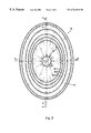
- FIG. 8 illustrates a front elevational view of an alternative detail to the detail illustrated in FIGS. 2 - 7 .
- a loudspeaker 9 includes a supporting frame 10 and a motor assembly.
- the illustrated motor assembly includes a backplate/center pole 12 , a permanent magnet 13 , and a front plate 14 providing a substantially uniform magnetic field across an air gap 15 .
- a voice coil former 16 supports a voice coil 17 in the magnetic field.
- Current related to the program material to be transduced by the loudspeaker 9 drives the voice coil 17 , causing it to reciprocate axially in the air gap 15 in a known manner.
- a cone 18 attached at its apex to an end of the coil former 16 lying outside the motor assembly is coupled by a surround 19 at its outer perimeter to the frame 10 .
- a spider 20 is coupled at its outer perimeter to the frame 10 .
- the spider 20 includes a central opening 22 to which the voice coil former 16 is attached.
- the suspension including the surround 19 and spider 20 constrains the voice coil 17 to reciprocate axially in the air gap 15 .
- the illustrated cone 18 is an approximately six inch (about 15.2 cm) by approximately nine inch (about 22.9 cm) elliptical cone approximately one inch (about 2.5 cm) deep.
- FIG. 8 illustrates a front elevational view of such a cone 18 ′.
- Cone 18 is constructed using, for example, a water-resistant or waterproof paper pulp, and a water-resistant or waterproof foam surround 19 .
- the pulp from which cone 18 is formed is bleached and unbleached fibers with water-resistant silicone treatment.
- Paper is hygroscopic, so it expands as it takes up moisture and shrinks as it releases moisture.
- the silicone treatment reduces the hygroscopic nature of the paper so that it does not take up as much water from the atmosphere. Since it does not take up so much water, it of course does not release as much either.
- Cone 18 has cross sections that are circular arcs intersecting straight lines. Cone 18 also employs decoupling ribs 28 in its contour. This geometry is intended to distribute uniformly the stress of expansion and contraction due to swelling and shrinkage as water is taken up and released by the cone 18 material.
- the radially inner section 30 of cone 18 has a radius of curvature of, for example, 111.34 inches (about 282.8 cm). This section is tangent to the outer, generally straight line section 32 of cone 18 at points 34 at a radius of about 1.8 inches (about 4.578 cm) along the major axis of the ellipse from the axis 23 of the cone 18 and of the speaker 9 . As best illustrated in FIGS.
- the decoupling ribs 28 are positioned at radii of about 1.74 inches (about 4.43 cm) along the ellipse's minor axis from the axis 23 of the cone 18 (decoupling rib 28 - 1 ), about 1.93 inches (about 4.89 cm) along the ellipse's minor axis from the axis 23 of the cone 18 (decoupling rib 28 - 2 ), and about 2.11 inches (about 5.37 cm) along the ellipse's minor axis from the axis 23 of the cone 18 (decoupling rib 28 - 3 ).
- the foam from which surround 19 is formed illustratively is polyethylene terephthalate (PET) foam.
- PET polyethylene terephthalate
- surround 19 has a generally parabolic cross section, as opposed to prior art semicircular cross sections.
- the radius of curvature 36 of the surround 19 adjacent frame 10 is about 0.06 inch (about 1.6 mm) on the side of surround 19 which is mounted to cone 18 .
- the radius of curvature 38 of the surround 19 adjacent cone 18 is about 0.08 inch (about 2.14 mm) on the cone 18 side, and the radius of curvature 40 of the surround 19 on the side thereof which is not mounted to cone 18 is about 0.55 inch (about 13.97 mm).
- the height of the surround 19 is about 0.19 inch (about 4.81 mm).
- the material from which surround 19 is formed is not hygroscopic.
Abstract
Description
Claims (26)
Priority Applications (1)
| Application Number | Priority Date | Filing Date | Title |
|---|---|---|---|
| US09/411,947 US6724910B1 (en) | 1999-10-04 | 1999-10-04 | Diaphragm stable through hygroscopic cycling |
Applications Claiming Priority (1)
| Application Number | Priority Date | Filing Date | Title |
|---|---|---|---|
| US09/411,947 US6724910B1 (en) | 1999-10-04 | 1999-10-04 | Diaphragm stable through hygroscopic cycling |
Publications (1)
| Publication Number | Publication Date |
|---|---|
| US6724910B1 true US6724910B1 (en) | 2004-04-20 |
Family
ID=32069708
Family Applications (1)
| Application Number | Title | Priority Date | Filing Date |
|---|---|---|---|
| US09/411,947 Expired - Lifetime US6724910B1 (en) | 1999-10-04 | 1999-10-04 | Diaphragm stable through hygroscopic cycling |
Country Status (1)
| Country | Link |
|---|---|
| US (1) | US6724910B1 (en) |
Cited By (7)
| Publication number | Priority date | Publication date | Assignee | Title |
|---|---|---|---|---|
| US20030081804A1 (en) * | 2001-08-08 | 2003-05-01 | Gn Resound North America Corporation | Dynamic range compression using digital frequency warping |
| US20050180588A1 (en) * | 2003-09-11 | 2005-08-18 | Martin Opitz | Transducer with deformable corner |
| US20080024036A1 (en) * | 2005-02-18 | 2008-01-31 | Martin Opitz | Transducer membrane with symmetrical curvature |
| US20090169049A1 (en) * | 2007-12-28 | 2009-07-02 | Szu-Wei Sun | Low Profile Audio Speaker |
| US10291997B2 (en) * | 2015-04-20 | 2019-05-14 | Goertek Inc. | Speaker device |
| US10375478B2 (en) * | 2016-12-13 | 2019-08-06 | Panasonic Intellectual Property Management Co., Ltd. | Loudspeaker diaphragm and loudspeaker including same |
| EP4231665A1 (en) * | 2022-02-21 | 2023-08-23 | Alps Alpine Co., Ltd. | Speaker |
Citations (21)
| Publication number | Priority date | Publication date | Assignee | Title |
|---|---|---|---|---|
| US3221834A (en) * | 1963-05-09 | 1965-12-07 | Hawley Products Co | Acoustic diaphragm |
| US3612783A (en) | 1967-07-05 | 1971-10-12 | Philips Corp | Foam diaphragm for loudspeaker |
| US3780232A (en) | 1971-01-04 | 1973-12-18 | Rola Celestion Ltd | Loudspeaker diaphragm |
| US3834486A (en) | 1971-05-28 | 1974-09-10 | Matsushita Electric Ind Co Ltd | Vibration diaphragm and cone edge of a loudspeaker |
| US3858680A (en) | 1971-05-28 | 1975-01-07 | Matsushita Electric Ind Co Ltd | Vibration diaphragm and cfne edge of a loudspeaker |
| US3946832A (en) | 1973-12-14 | 1976-03-30 | Matsushita Electric Industrial Co., Ltd. | Diaphragm for loud speaker |
| US3987258A (en) * | 1974-04-30 | 1976-10-19 | Matsushita Electric Industrial Co., Ltd. | Water-proof sound apparatus |
| US3997023A (en) * | 1975-12-10 | 1976-12-14 | White Stanley F | Loudspeaker with improved surround |
| US4071111A (en) | 1976-04-28 | 1978-01-31 | Acoustic Fiber Sound Systems, Inc. | Weatherproof loudspeaker assembly and method of making same |
| US4140203A (en) | 1976-05-17 | 1979-02-20 | Matsushita Electric Industrial Co., Ltd. | Acoustic diaphragm with polyurethane elastomer coating |
| US4319098A (en) * | 1980-04-30 | 1982-03-09 | Motorola, Inc. | Loudspeaker having a unitary mechanical-acoustic diaphragm termination |
| US4410768A (en) * | 1980-07-23 | 1983-10-18 | Nippon Gakki Seizo Kabushiki Kaisha | Electro-acoustic transducer |
| US4478309A (en) | 1981-06-19 | 1984-10-23 | Hitachi, Ltd. | Speaker equipped with diaphragm filled with foamed resin |
| US4552243A (en) * | 1984-05-03 | 1985-11-12 | Pioneer Industrial Components, Inc. | Diaphragm material for acoustical transducer |
| US4554414A (en) * | 1983-04-28 | 1985-11-19 | Harman International Industries Incorporated | Multi-driver loudspeaker |
| US5008945A (en) | 1988-05-23 | 1991-04-16 | Pioneer Electronic Corp. | Water-proof speaker unit |
| US5319718A (en) | 1991-10-11 | 1994-06-07 | Yocum Fred D | Loudspeaker cone and method for making same |
| US5650105A (en) | 1994-05-24 | 1997-07-22 | Yocum; Fred D. | Method for making a loudspeaker cone with an integral surround |
| US5734734A (en) | 1995-12-29 | 1998-03-31 | Proni; Lucio | Audio voice coil adaptor ring |
| US6026929A (en) * | 1997-11-10 | 2000-02-22 | Single Source Technology And Development, Inc. | High frequency radially arcuated center speaker cone with variable thickness |
| US6111969A (en) * | 1997-05-09 | 2000-08-29 | Babb; Burton A. | High fidelity, broad band acoustic loudspeaker |
-
1999
- 1999-10-04 US US09/411,947 patent/US6724910B1/en not_active Expired - Lifetime
Patent Citations (21)
| Publication number | Priority date | Publication date | Assignee | Title |
|---|---|---|---|---|
| US3221834A (en) * | 1963-05-09 | 1965-12-07 | Hawley Products Co | Acoustic diaphragm |
| US3612783A (en) | 1967-07-05 | 1971-10-12 | Philips Corp | Foam diaphragm for loudspeaker |
| US3780232A (en) | 1971-01-04 | 1973-12-18 | Rola Celestion Ltd | Loudspeaker diaphragm |
| US3834486A (en) | 1971-05-28 | 1974-09-10 | Matsushita Electric Ind Co Ltd | Vibration diaphragm and cone edge of a loudspeaker |
| US3858680A (en) | 1971-05-28 | 1975-01-07 | Matsushita Electric Ind Co Ltd | Vibration diaphragm and cfne edge of a loudspeaker |
| US3946832A (en) | 1973-12-14 | 1976-03-30 | Matsushita Electric Industrial Co., Ltd. | Diaphragm for loud speaker |
| US3987258A (en) * | 1974-04-30 | 1976-10-19 | Matsushita Electric Industrial Co., Ltd. | Water-proof sound apparatus |
| US3997023A (en) * | 1975-12-10 | 1976-12-14 | White Stanley F | Loudspeaker with improved surround |
| US4071111A (en) | 1976-04-28 | 1978-01-31 | Acoustic Fiber Sound Systems, Inc. | Weatherproof loudspeaker assembly and method of making same |
| US4140203A (en) | 1976-05-17 | 1979-02-20 | Matsushita Electric Industrial Co., Ltd. | Acoustic diaphragm with polyurethane elastomer coating |
| US4319098A (en) * | 1980-04-30 | 1982-03-09 | Motorola, Inc. | Loudspeaker having a unitary mechanical-acoustic diaphragm termination |
| US4410768A (en) * | 1980-07-23 | 1983-10-18 | Nippon Gakki Seizo Kabushiki Kaisha | Electro-acoustic transducer |
| US4478309A (en) | 1981-06-19 | 1984-10-23 | Hitachi, Ltd. | Speaker equipped with diaphragm filled with foamed resin |
| US4554414A (en) * | 1983-04-28 | 1985-11-19 | Harman International Industries Incorporated | Multi-driver loudspeaker |
| US4552243A (en) * | 1984-05-03 | 1985-11-12 | Pioneer Industrial Components, Inc. | Diaphragm material for acoustical transducer |
| US5008945A (en) | 1988-05-23 | 1991-04-16 | Pioneer Electronic Corp. | Water-proof speaker unit |
| US5319718A (en) | 1991-10-11 | 1994-06-07 | Yocum Fred D | Loudspeaker cone and method for making same |
| US5650105A (en) | 1994-05-24 | 1997-07-22 | Yocum; Fred D. | Method for making a loudspeaker cone with an integral surround |
| US5734734A (en) | 1995-12-29 | 1998-03-31 | Proni; Lucio | Audio voice coil adaptor ring |
| US6111969A (en) * | 1997-05-09 | 2000-08-29 | Babb; Burton A. | High fidelity, broad band acoustic loudspeaker |
| US6026929A (en) * | 1997-11-10 | 2000-02-22 | Single Source Technology And Development, Inc. | High frequency radially arcuated center speaker cone with variable thickness |
Cited By (12)
| Publication number | Priority date | Publication date | Assignee | Title |
|---|---|---|---|---|
| US20030081804A1 (en) * | 2001-08-08 | 2003-05-01 | Gn Resound North America Corporation | Dynamic range compression using digital frequency warping |
| US7277554B2 (en) | 2001-08-08 | 2007-10-02 | Gn Resound North America Corporation | Dynamic range compression using digital frequency warping |
| US7343022B2 (en) | 2001-08-08 | 2008-03-11 | Gn Resound A/S | Spectral enhancement using digital frequency warping |
| US20050180588A1 (en) * | 2003-09-11 | 2005-08-18 | Martin Opitz | Transducer with deformable corner |
| US7711137B2 (en) | 2003-09-11 | 2010-05-04 | Akg Acoustics Gmbh | Transducer with deformable corner |
| US8411894B2 (en) | 2003-09-11 | 2013-04-02 | AKG Acoustrics GmbH | Transducer with deformable corner |
| US20080024036A1 (en) * | 2005-02-18 | 2008-01-31 | Martin Opitz | Transducer membrane with symmetrical curvature |
| US8208679B2 (en) * | 2005-02-18 | 2012-06-26 | Akg Acoustics Gmbh | Transducer membrane with symmetrical curvature |
| US20090169049A1 (en) * | 2007-12-28 | 2009-07-02 | Szu-Wei Sun | Low Profile Audio Speaker |
| US10291997B2 (en) * | 2015-04-20 | 2019-05-14 | Goertek Inc. | Speaker device |
| US10375478B2 (en) * | 2016-12-13 | 2019-08-06 | Panasonic Intellectual Property Management Co., Ltd. | Loudspeaker diaphragm and loudspeaker including same |
| EP4231665A1 (en) * | 2022-02-21 | 2023-08-23 | Alps Alpine Co., Ltd. | Speaker |
Similar Documents
| Publication | Publication Date | Title |
|---|---|---|
| KR100586140B1 (en) | Bone conduction speaker | |
| EP0068285A1 (en) | Speaker equipped with diaphragm filled with foamed resin | |
| US6496590B2 (en) | Loudspeaker with improved diaphragm | |
| US6724910B1 (en) | Diaphragm stable through hygroscopic cycling | |
| US5123053A (en) | Loudspeaker suspension | |
| US20050190942A1 (en) | Microphone gasket with integrated acoustic resistance | |
| CN104105025A (en) | Trumpet structure with integrated active loudspeaker and passive radiator, and sound box | |
| US3718779A (en) | Loudspeaker diaphragm having marginal air release passages and center high frequency propagator | |
| US6567528B1 (en) | Offset apex spider | |
| CN208063452U (en) | Voice coil and microphone | |
| JP2002078075A (en) | Diaphragm for speaker | |
| US11765517B2 (en) | Sound production unit and speaker | |
| KR19990044918A (en) | Radially Bowed High Frequency Center Speaker Cone | |
| CN208241842U (en) | Earphone and electronic equipment | |
| JP3245074B2 (en) | Double dome diaphragm and speaker using it | |
| JP2006100879A (en) | Ring type speaker | |
| CN209057360U (en) | A kind of vibration component, loudspeaker and speaker | |
| JPH11317997A (en) | Speaker and diaphragm for speaker | |
| CN219834376U (en) | Loudspeaker | |
| CN218959122U (en) | Loudspeaker | |
| JP2557857Y2 (en) | Cone type speaker | |
| JPS5824547Y2 (en) | Sound pressure type electric ↓-acoustic transducer | |
| JPS5844709Y2 (en) | speaker | |
| JP2754535B2 (en) | Speaker | |
| JPH01103400A (en) | Diaphragm for speaker |
Legal Events
| Date | Code | Title | Description |
|---|---|---|---|
| AS | Assignment |
Owner name: HARMAN INTERNATIONAL INDUSTRIES, INCORPORATED, CAL Free format text: ASSIGNMENT OF ASSIGNORS INTEREST;ASSIGNORS:HEED, THOMAS P.;BRISTOL, KIRK R.;MALINOWSKI, WILLIAM J., JR.;REEL/FRAME:010322/0846;SIGNING DATES FROM 19990907 TO 19990917 |
|
| AS | Assignment |
Owner name: HARMAN INTERNATIONAL INDUSTRIES, INCORPORATED, CAL Free format text: ASSIGNMENT OF ASSIGNORS INTEREST;ASSIGNORS:HEED, THOMAS P.;BRISTOL, KIRK R.;MALINOWSKI, WILLIAM J. JR.;REEL/FRAME:010631/0220;SIGNING DATES FROM 19990907 TO 19990917 |
|
| FEPP | Fee payment procedure |
Free format text: PAYOR NUMBER ASSIGNED (ORIGINAL EVENT CODE: ASPN); ENTITY STATUS OF PATENT OWNER: LARGE ENTITY Free format text: PAYER NUMBER DE-ASSIGNED (ORIGINAL EVENT CODE: RMPN); ENTITY STATUS OF PATENT OWNER: LARGE ENTITY |
|
| STCF | Information on status: patent grant |
Free format text: PATENTED CASE |
|
| FPAY | Fee payment |
Year of fee payment: 4 |
|
| REMI | Maintenance fee reminder mailed | ||
| AS | Assignment |
Owner name: JPMORGAN CHASE BANK, N.A., NEW YORK Free format text: SECURITY AGREEMENT;ASSIGNORS:HARMAN INTERNATIONAL INDUSTRIES, INCORPORATED;BECKER SERVICE-UND VERWALTUNG GMBH;CROWN AUDIO, INC.;AND OTHERS;REEL/FRAME:022659/0743 Effective date: 20090331 Owner name: JPMORGAN CHASE BANK, N.A.,NEW YORK Free format text: SECURITY AGREEMENT;ASSIGNORS:HARMAN INTERNATIONAL INDUSTRIES, INCORPORATED;BECKER SERVICE-UND VERWALTUNG GMBH;CROWN AUDIO, INC.;AND OTHERS;REEL/FRAME:022659/0743 Effective date: 20090331 |
|
| AS | Assignment |
Owner name: HARMAN BECKER AUTOMOTIVE SYSTEMS GMBH, CONNECTICUT Free format text: RELEASE;ASSIGNOR:JPMORGAN CHASE BANK, N.A., AS ADMINISTRATIVE AGENT;REEL/FRAME:025795/0143 Effective date: 20101201 Owner name: HARMAN INTERNATIONAL INDUSTRIES, INCORPORATED, CON Free format text: RELEASE;ASSIGNOR:JPMORGAN CHASE BANK, N.A., AS ADMINISTRATIVE AGENT;REEL/FRAME:025795/0143 Effective date: 20101201 |
|
| AS | Assignment |
Owner name: JPMORGAN CHASE BANK, N.A., AS ADMINISTRATIVE AGENT Free format text: SECURITY AGREEMENT;ASSIGNORS:HARMAN INTERNATIONAL INDUSTRIES, INCORPORATED;HARMAN BECKER AUTOMOTIVE SYSTEMS GMBH;REEL/FRAME:025823/0354 Effective date: 20101201 |
|
| FPAY | Fee payment |
Year of fee payment: 8 |
|
| AS | Assignment |
Owner name: HARMAN BECKER AUTOMOTIVE SYSTEMS GMBH, CONNECTICUT Free format text: RELEASE;ASSIGNOR:JPMORGAN CHASE BANK, N.A., AS ADMINISTRATIVE AGENT;REEL/FRAME:029294/0254 Effective date: 20121010 Owner name: HARMAN INTERNATIONAL INDUSTRIES, INCORPORATED, CON Free format text: RELEASE;ASSIGNOR:JPMORGAN CHASE BANK, N.A., AS ADMINISTRATIVE AGENT;REEL/FRAME:029294/0254 Effective date: 20121010 |
|
| FPAY | Fee payment |
Year of fee payment: 12 |