US6719575B2 - Lever-type connector - Google Patents
Lever-type connector Download PDFInfo
- Publication number
- US6719575B2 US6719575B2 US10/127,562 US12756202A US6719575B2 US 6719575 B2 US6719575 B2 US 6719575B2 US 12756202 A US12756202 A US 12756202A US 6719575 B2 US6719575 B2 US 6719575B2
- Authority
- US
- United States
- Prior art keywords
- lever
- connector
- arm parts
- connector housing
- end portions
- Prior art date
- Legal status (The legal status is an assumption and is not a legal conclusion. Google has not performed a legal analysis and makes no representation as to the accuracy of the status listed.)
- Expired - Fee Related
Links
Images


Classifications
-
- H—ELECTRICITY
- H01—ELECTRIC ELEMENTS
- H01R—ELECTRICALLY-CONDUCTIVE CONNECTIONS; STRUCTURAL ASSOCIATIONS OF A PLURALITY OF MUTUALLY-INSULATED ELECTRICAL CONNECTING ELEMENTS; COUPLING DEVICES; CURRENT COLLECTORS
- H01R13/00—Details of coupling devices of the kinds covered by groups H01R12/70 or H01R24/00 - H01R33/00
- H01R13/62—Means for facilitating engagement or disengagement of coupling parts or for holding them in engagement
- H01R13/629—Additional means for facilitating engagement or disengagement of coupling parts, e.g. aligning or guiding means, levers, gas pressure electrical locking indicators, manufacturing tolerances
- H01R13/62933—Comprising exclusively pivoting lever
-
- H—ELECTRICITY
- H01—ELECTRIC ELEMENTS
- H01R—ELECTRICALLY-CONDUCTIVE CONNECTIONS; STRUCTURAL ASSOCIATIONS OF A PLURALITY OF MUTUALLY-INSULATED ELECTRICAL CONNECTING ELEMENTS; COUPLING DEVICES; CURRENT COLLECTORS
- H01R13/00—Details of coupling devices of the kinds covered by groups H01R12/70 or H01R24/00 - H01R33/00
- H01R13/46—Bases; Cases
- H01R13/52—Dustproof, splashproof, drip-proof, waterproof, or flameproof cases
- H01R13/5219—Sealing means between coupling parts, e.g. interfacial seal
Definitions
- the present invention relates to a lever-type connector.
- a lever 102 of the connector 100 includes an operation part 103 formed narrow and long in the right and left direction thereof, and a pair of plate-shaped arm parts 104 respectively projected from the two end portions of the operation part 103 , while there are formed two cam grooves 105 respectively in the two arm parts 104 ; and, two bearing holes 107 respectively formed in the two arm parts 104 are fitted with their associated support shafts 106 provided on and projected from the right and left outer side surfaces of a connector housing 101 , whereby the lever 102 can be rotatably supported on the connector housing 101 .
- the lever 102 When fitting this lever-side connector 100 with its mating connector (not shown), the lever 102 is positioned at a given wait position and the entrances of the cam grooves 105 are opened toward the cam pins (not shown) of the mating connector; and, in this state, the two connectors are moved closer to each other to thereby advance the cam pins into the entrances of the cam grooves and, in this state, the lever 102 is rotated.
- the present invention aims at eliminating the drawbacks found in the above-mentioned conventional lever-type connector. Accordingly, it is an object of the invention to provide a lever-type connector which can prevent the lever against damage when the connector drops down onto the floor.
- a lever-type connector wherein a lever including an operation part and a pair of arm parts respectively extended from the two ends of the operation part, the arm parts of the lever being supported respectively on the two right and left outer side surfaces of a connector housing; the lever is situated at its wait position, the entrances of cam grooves respectively formed in the arm parts are opened toward a mating connector, cam pins are respectively moved into the entrances of the cam grooves, and the lever is rotated, thereby fitting the lever-type connector with the mating connector; and, in a state where the lever is situated at the wait position, the projecting end portions of the arm parts projected from the operation part face downward, characterized in that, in the two right and left end portions of the lower surface of the connector housing, there are disposed impact receive portions which, in a state where the lever is situated at the wait position, are projected downwardly of the projecting end portions of the arm parts.
- the impact receive portions are formed so as to be adjacent and opposed to the inner surfaces of the projecting end portions of the arm parts.
- the impact receive portions are formed so as to fill up clearances existing respectively between the projecting end portions of the arm parts and the outer side surfaces of the connector housing.
- a lever-type connector as set forth in the first aspect of the invention, when the present lever-type connector drops down in the posture that the lever is situated at the wait position and the projecting end portions of the arm parts face downward, the impact receive portions firstly collide with a drop surface and thus most of the drop impact of the lever-type connector is received by the impact receive portions. Therefore, there is hardly a possibility that the drop impact of the lever-type connector can be applied to the projecting end portions of the arm parts.
- the present lever-type connector drops down, there is a fear that, after the impact receive portions collide with the drop surface once, the lever-type connector can jump up and, when it drops down again, the projecting end portions of the arm parts can be butted against the drop surface or the projecting end portions of the arm parts can be butted against other members existing on the drop surface.
- the impact receive portions are respectively disposed adjacent and opposed to the inner surfaces of the projecting end portions of the arm parts, even in case where the projecting end portions of the arm parts are going to flex toward the outer side surfaces of the connector housing, the projecting end portions are contacted with the impact receive portions, which prevents the projecting end portions from flexing greatly. Therefore, there can be eliminated the fear that the lever can be broken or can be removed from the connector housing due to the flexed projecting end portions of the arm parts.
- the lever-type connector drops down, there is a fear that, after the impact receive portions collide with the drop surface once, the lever-type connector can jump up and, when it drops down again, the projecting end portions of the arm parts can be butted against the drop surface or the projecting end portions of the arm parts can be butted against other members existing on the drop surface.
- the clearances respectively existing between the projecting end portions of the arm parts and the outer side surfaces of the connector housing are filled up by the impact receive portions, there is no fear that the projecting end portions of the lever can be flexed toward the side surface side of the connector housing. This can eliminate the fear that the lever can be broken or can be removed from the connector housing due to the flexed projecting end portions of the arm parts.
- FIG. 1 is a perspective view of an embodiment 1 of a lever-type connector according to the invention, when it is viewed from the front surface thereof;
- FIG. 2 is a perspective view of the embodiment 1, when it is viewed from the back surface thereof;
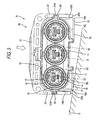
- FIG. 3 is a front view of the embodiment 1;
- FIG. 4 is a back view of the embodiment 1;
- FIG. 5 is a side view of the embodiment 1;
- FIG. 6 is a bottom view of the embodiment 1;
- FIG. 7 is a front view of another embodiment 2 of a lever-type connector according to the invention.
- FIG. 8 is a perspective view of a conventional lever-type connector.
- FIG. 9 is a front view of the above conventional lever-type connector.
- the lever-type connector A comprises a connector housing 10 made of synthetic resin and a lever 20 made of synthetic resin.
- the connector housing 10 there are disposed three forwardly projecting circular-shaped terminal hold parts 11 arranged in the right and left direction (in the horizontal direction) of the connector housing 10 , and a hood part 12 formed in an elliptical-like shape long in the horizontal direction for enclosing the three terminal hold parts 11 collectively.
- a hood part 12 formed in an elliptical-like shape long in the horizontal direction for enclosing the three terminal hold parts 11 collectively.
- female-terminal metal members 13 see FIG. 4 from behind the terminal hold parts 11 , respectively.
- shield shells 14 there are mounted on the connector housing 10 , each having a front end side portion divided into four pieces in the peripheral direction thereof in such a manner that the shield shells 14 extend along the outer peripheries of their respective terminal hold parts 11 .
- the shield shells 14 enclose the female-terminal metal members 13 stored within the terminal hold parts 11 to thereby fulfill their respective shield functions. Also, on the deep-side end face of the hood part 12 , there are projectingly formed three circular-shaped fitting barrel portions 15 (see FIG. 3) respectively concentric with their associated terminal hold parts 11 ; and, waterproofing seal rings 16 (see FIG. 3) are respectively fitted with the outer surfaces of the outer peripheries of their associated fitting barrel portions 15 . Further, a pair of support shafts 17 are respectively provided on and projected from the right and left outer side surfaces of the hood part 12 . In addition, in the hood part 12 , there are disposed escape grooves 18 each formed by cutting the hood part 12 narrow and long backwardly from the front end edge of the hood part 12 .
- the lever 20 comprises an operation part 21 narrow and long in the right and left direction of the lever 20 and a pair of plate-shaped arm parts 22 which project in parallel to each other from the right and left end portions of the operation part 21 , while the operation part 21 and the pair of arm parts 22 are molded into an integral unit.
- the arm parts 22 there are formed bearing holes 23 respectively; and, in case where the bearing holes 23 are respectively fitted with their associated support shafts 17 , the lever 20 can be rotatably mounted on the connector housing 10 .
- cam grooves 24 respectively having their entrances 24 A opened on the outer peripheral edges of the arm parts 22 .
- Each of the cam grooves 24 has a substantially spiral shape with the bearing hole 23 of the arm part 20 as the center thereof, while each cam groove 24 approaches its associated bearing hole 23 as it goes toward the deep portion thereof.
- a mating connector B is formed in a horizontally long elliptic shape which can be fitted with the lever-type connector A in such a manner that it extends along the inner periphery of the hood part 12 .
- the front surface (the surface that faces the lever-type connector A) of the mating connector B there are formed three fitting recessed portions 30 into which the three fitting barrel portions 15 can be respectively fitted.
- the seal rings 16 on the outer peripheries of the fitting barrel portions 15 while they are elastically flexed, are slidingly contacted with the inner peripheries of the fitting recessed portions 30 .
- shield shells 31 (see FIG. 3) which can be contacted with the outer surfaces of the shield shells 14 of the lever-type connector A.
- the inside diameter dimension of each of the shield shells 31 in the free state thereof is set smaller than the outside diameter of each of the shield shells 14 of the lever-type connector A.
- the shield shells 31 while they are elastically flexed in the diameter enlarging direction thereof, are slidingly contacted with the shield shells 14 respectively.
- a pair of cam pins 32 there are projectingly provided on the right and left outer side surfaces of the mating connector B.
- the lever 20 is rotated to its wait position, and the entrances 24 A of the cam grooves 24 are not only opened forwardly (that is, in the direction that corresponds to the cam pins 32 of the mating connector B) but also held in the states thereof in which they correspond to the escape grooves 18 of the hood parts 12 (see FIG. 3 ).
- the lever-type connector A is moved nearer to the mating connector B, the cam pins 32 are respectively moved into the entrances 24 A of their associated cam grooves 24 , and the hood parts 12 are slightly fitted with the outer surface of the mating connector B.
- the lever-type connector A is drawn close to the mating connector B.
- frictional resistance which is caused by the elastic sliding contact between the shield shells 14 and 31 ; frictional resistance caused by the elastic sliding contact between the seal rings 16 and the inner peripheries of the fitting recessed portions; and, frictional resistance caused by the elastic sliding contact between the female-terminal metal members 13 and male-terminal metal members (see FIG. 3 ).
- These three kinds of frictional resistance provide obstacles to the smooth fitting operation.
- due to a cam action (leverage) through the engagement between the cam grooves 24 and cam pins 32 attained by the rotational movement of the lever 20 even in case where the operation force of the lever 20 is small, the fitting operation of the two connectors A and B can be advanced smoothly.
- each of the impact receive portions 19 is formed in a shape which fills up a clearance between the projecting end portion 22 A of the arm part 22 and the outer surface of the hood part 12 ; and, therefore, in a state where the lever 20 is present at the wait position, the flat-shaped outer surfaces 19 S of the impact receive portions 19 are opposed to the inner surfaces of the arm parts 22 with few clearance between them. Also, the lower surfaces 19 L of the impact receive portions 19 are formed flush and continuous with the lower surface of the hood part 12 .
- the corner edge portion 19 A of the present impact receive portion 19 which is a connecting portion between the lower surface 19 L and outer side surface 19 S of the present impact receive portion 19 , collides with the drop surface G. That is, in case where the lever-type connector A drops down substantially in the same posture as the posture thereof when it is fitted with the mating connector B (in the position where the projecting end portions 22 A of the arm parts 22 face substantially downward), the arm parts of the lever 20 can be prevented from colliding with the drop surface and thus the drop impact of the lever-type connector A can be hardly applied onto the projecting portions 22 A of the arm parts 22 .
- the outer side surfaces 19 S of the impact receive portions 19 are disposed adjacent and opposed to the inner surfaces of the projecting end portions 22 A of the arm parts 22 , even in case where the projecting end portions 22 A of the arm parts 22 are going to flex toward the outer surface sides of the connector housing 10 (hood part 12 ), at the time when the projecting end portions 22 A are flexed slightly, the projecting end portions 22 A are contacted with the outer side surfaces 19 S of the impact receive portions 19 , so that the projecting end portions 22 A are prevented from flexing greatly.
- the lever 20 can be prevented against breakage or can be prevented against removal from the connector housing 10 due to the flexed projecting end portions 22 A.
- the present embodiment is different from the above-mentioned first embodiment 1 in the structure of the impact receive portions 35 thereof.
- the remaining portions of the present embodiment are the same as those of the embodiment 1. Therefore, the same parts of the present embodiment are given the same designations and thus the description of the structures, operations and effects thereof is omitted here.
- the impact receive portions 35 in the present embodiment 2 are respectively formed in the two right and left end portions of the lower surface of the hood part 12 and, in a state where the lever 20 is situated at the wait position, are projected downwardly of the projecting end portions 22 A of the arm parts 22 . Also, in the impact receive portions 35 , there are respectively formed protection portions 36 which extend outwardly in the horizontal direction, while the protection portions 36 are respectively disposed adjacent and opposed to the lower edges of the projecting end portions 22 A of the arm parts 22 .
- the impact receive portions 35 similarly to the impact receive portions 19 according to the embodiment 1, fill up clearances respectively existing between the projecting end portions 22 A of the arm parts 22 and the outer side surfaces of the hood part 12 ; and, the flat-shaped outer surfaces 35 S of the impact receive portions 35 are opposed to the inner surfaces of the arm parts 22 with little clearance between them.
- the impact receive portions 35 according to the present embodiment 2 include the protection portions 36 , even in case where the angle of inclination of the inclined posture of the lever-type connector B when it drops down is larger than in the embodiment 1, the projecting end portions 22 A of the arm parts 22 can be positively prevented against collision with the drop surfaces G.
- the impact receive portions are formed so as to fill up the clearances respectively existing between the outer side surfaces of the connector housing and the projecting end portions of the arm parts.
- the impact receive portions can also be provided at and projected from positions relatively adjacent to the projecting end portions of the arm parts in such a manner that the clearances between the connector housing and the arm parts are not filled up by the impact receive portions but remain as they are.
- lever-type connector having a waterproof function and a shield function.
- the invention can also apply to a lever-type connector having one of a waterproof function and a shield function, or a lever-type connector having neither a waterproof function nor a shield function.
- the impact receive portions are formed so as to be adjacent and opposed to the inner surfaces of the projecting end portions of the arm parts.
- the impact receive portions can also be formed such that they have relatively large clearances with respect to the projecting end portions of the arm parts.
- the impact receive portions are formed so as to fill up the clearances between the projecting end portions of the arm parts and the outer side surfaces of the connector housing (hood part).
- the impact receive portions can also be formed so as not to fill up the clearances respectively existing between the projecting end portions of the arm parts and the outer side surfaces of the connector housing (hood part).
Landscapes
- Details Of Connecting Devices For Male And Female Coupling (AREA)
Abstract
Description
Claims (11)
Applications Claiming Priority (2)
| Application Number | Priority Date | Filing Date | Title |
|---|---|---|---|
| JP2001-125533 | 2001-04-24 | ||
| JP2001125533A JP3939932B2 (en) | 2001-04-24 | 2001-04-24 | Lever type connector |
Publications (2)
| Publication Number | Publication Date |
|---|---|
| US20020173184A1 US20020173184A1 (en) | 2002-11-21 |
| US6719575B2 true US6719575B2 (en) | 2004-04-13 |
Family
ID=18974737
Family Applications (1)
| Application Number | Title | Priority Date | Filing Date |
|---|---|---|---|
| US10/127,562 Expired - Fee Related US6719575B2 (en) | 2001-04-24 | 2002-04-23 | Lever-type connector |
Country Status (3)
| Country | Link |
|---|---|
| US (1) | US6719575B2 (en) |
| JP (1) | JP3939932B2 (en) |
| DE (1) | DE10218113A1 (en) |
Families Citing this family (5)
| Publication number | Priority date | Publication date | Assignee | Title |
|---|---|---|---|---|
| JP4830920B2 (en) * | 2007-03-09 | 2011-12-07 | 住友電装株式会社 | Lever type connector |
| DE102010002681B4 (en) * | 2010-03-09 | 2018-10-18 | Te Connectivity Germany Gmbh | Electrical connector, electrical connector and assembled electrical cable |
| KR20150105993A (en) * | 2013-01-15 | 2015-09-18 | 델피 인터내셔널 오퍼레이션즈 룩셈부르크 에스.에이 알.엘. | Sealed electrical connector assembly |
| JP6042856B2 (en) * | 2014-09-29 | 2016-12-14 | 矢崎総業株式会社 | Connector housing |
| JP2018181404A (en) * | 2017-04-03 | 2018-11-15 | タイコエレクトロニクスジャパン合同会社 | Electrical connector |
Citations (4)
| Publication number | Priority date | Publication date | Assignee | Title |
|---|---|---|---|---|
| US5476705A (en) | 1993-06-22 | 1995-12-19 | Yazaki Corporation | Corner structure of resinous molded part |
| US5609494A (en) * | 1994-11-30 | 1997-03-11 | Yazaki Corporation | Connector lever locking mechanism |
| US5904583A (en) * | 1993-11-05 | 1999-05-18 | Sumitomo Wiring Systems, Ltd. | Lever connector |
| US5913691A (en) * | 1996-08-20 | 1999-06-22 | Chrysler Corporation | Dual power/control connector |
-
2001
- 2001-04-24 JP JP2001125533A patent/JP3939932B2/en not_active Expired - Fee Related
-
2002
- 2002-04-23 DE DE10218113A patent/DE10218113A1/en not_active Withdrawn
- 2002-04-23 US US10/127,562 patent/US6719575B2/en not_active Expired - Fee Related
Patent Citations (4)
| Publication number | Priority date | Publication date | Assignee | Title |
|---|---|---|---|---|
| US5476705A (en) | 1993-06-22 | 1995-12-19 | Yazaki Corporation | Corner structure of resinous molded part |
| US5904583A (en) * | 1993-11-05 | 1999-05-18 | Sumitomo Wiring Systems, Ltd. | Lever connector |
| US5609494A (en) * | 1994-11-30 | 1997-03-11 | Yazaki Corporation | Connector lever locking mechanism |
| US5913691A (en) * | 1996-08-20 | 1999-06-22 | Chrysler Corporation | Dual power/control connector |
Also Published As
| Publication number | Publication date |
|---|---|
| JP2002324622A (en) | 2002-11-08 |
| DE10218113A1 (en) | 2002-12-12 |
| JP3939932B2 (en) | 2007-07-04 |
| US20020173184A1 (en) | 2002-11-21 |
Similar Documents
| Publication | Publication Date | Title |
|---|---|---|
| US7354310B1 (en) | Electrical connector housing cover | |
| JP3601474B2 (en) | Lever type connector | |
| EP1174955B1 (en) | Electrical connector | |
| CA2420961A1 (en) | Mate assist assembly for connecting electrical contacts | |
| US6382992B1 (en) | Electrical connector assembly with improved camming system | |
| CN103636077B (en) | Lever-fitting-type connector | |
| US20100311258A1 (en) | Connector assembly having improved cover | |
| EP1355385A2 (en) | Rack and pinion electrical connector with offset gear teeth | |
| EP1882287B1 (en) | Electrical connector with a locking mechanism | |
| US20110086529A1 (en) | Lever-type connector | |
| KR100875862B1 (en) | Dustproof Connectors | |
| US7445475B2 (en) | Lever type connector | |
| US6719575B2 (en) | Lever-type connector | |
| EP1679768B1 (en) | A connector and connector assembly | |
| US9917395B2 (en) | Lever-type connector | |
| WO2021044678A1 (en) | Lever-operated connector | |
| JP3709174B2 (en) | Flexible board connector | |
| JP6874015B2 (en) | Connector assembly | |
| JP3841080B2 (en) | Battery Charger | |
| JP2019110015A (en) | Lever type connector | |
| JP6387448B1 (en) | Harness side connector and card edge connector | |
| JP3533692B2 (en) | Connection device | |
| JP2004063093A (en) | Card connector | |
| JP7218268B2 (en) | Regulating member and connector assembly | |
| JPH07183062A (en) | Connector for wiring |
Legal Events
| Date | Code | Title | Description |
|---|---|---|---|
| AS | Assignment |
Owner name: AUTONETWORKS TECHNOLOGIES, LTD., JAPAN Free format text: ASSIGNMENT OF ASSIGNORS INTEREST;ASSIGNOR:MIYAZAKI, SHO;REEL/FRAME:012988/0825 Effective date: 20020531 Owner name: SUMITOMO WIRING SYSTEMS, LTD., JAPAN Free format text: ASSIGNMENT OF ASSIGNORS INTEREST;ASSIGNOR:MIYAZAKI, SHO;REEL/FRAME:012988/0825 Effective date: 20020531 Owner name: SUMITOMO ELECTRIC INDUSTRIES, LTD., JAPAN Free format text: ASSIGNMENT OF ASSIGNORS INTEREST;ASSIGNOR:MIYAZAKI, SHO;REEL/FRAME:012988/0825 Effective date: 20020531 |
|
| FEPP | Fee payment procedure |
Free format text: PAYOR NUMBER ASSIGNED (ORIGINAL EVENT CODE: ASPN); ENTITY STATUS OF PATENT OWNER: LARGE ENTITY |
|
| FPAY | Fee payment |
Year of fee payment: 4 |
|
| FPAY | Fee payment |
Year of fee payment: 8 |
|
| REMI | Maintenance fee reminder mailed | ||
| LAPS | Lapse for failure to pay maintenance fees | ||
| STCH | Information on status: patent discontinuation |
Free format text: PATENT EXPIRED DUE TO NONPAYMENT OF MAINTENANCE FEES UNDER 37 CFR 1.362 |
|
| STCH | Information on status: patent discontinuation |
Free format text: PATENT EXPIRED DUE TO NONPAYMENT OF MAINTENANCE FEES UNDER 37 CFR 1.362 |
|
| FP | Lapsed due to failure to pay maintenance fee |
Effective date: 20160413 |