US6701029B1 - Ring-wedge data analysis of digital images - Google Patents
Ring-wedge data analysis of digital images Download PDFInfo
- Publication number
- US6701029B1 US6701029B1 US09/501,546 US50154600A US6701029B1 US 6701029 B1 US6701029 B1 US 6701029B1 US 50154600 A US50154600 A US 50154600A US 6701029 B1 US6701029 B1 US 6701029B1
- Authority
- US
- United States
- Prior art keywords
- ring
- image
- additionally
- wedge
- employing
- Prior art date
- Legal status (The legal status is an assumption and is not a legal conclusion. Google has not performed a legal analysis and makes no representation as to the accuracy of the status listed.)
- Expired - Lifetime
Links
Images

Classifications
-
- G—PHYSICS
- G06—COMPUTING; CALCULATING OR COUNTING
- G06V—IMAGE OR VIDEO RECOGNITION OR UNDERSTANDING
- G06V10/00—Arrangements for image or video recognition or understanding
- G06V10/40—Extraction of image or video features
- G06V10/42—Global feature extraction by analysis of the whole pattern, e.g. using frequency domain transformations or autocorrelation
- G06V10/431—Frequency domain transformation; Autocorrelation
Definitions
- the present invention relates to image classification and recognition based on spatial frequency sampling as well as image domain sampling.
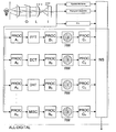
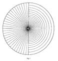
- U.S. Pat. No. 3,687,772 disclosed a robotic-eye photodetector called a ring-wedge photodetector. As shown in FIG. 1, this photodetector preferably has 32 separate annular semi-rings for sampling power spectral density, independently of rotation, and 32 pie-shaped segments devised for readout of edges and edge-angle correlation.
- the wedge data are scale-invariant.
- the photodetector is placed in the back focal plane of a Fourier-optical processor.
- the entire system includes a laser illuminator, an input picture being inspected, a Fourier-transform lens, and the ring-wedge photodetector in the back focal plane that is also known as the optical-transform plane.
- Each of the 64 photodetectors on the ring-wedge photodetector has a separate amplifier and digitizer so that the sampled Fourier transform signal can be coupled into an electronic digital computer.
- the present invention provides a software system both for recognition and classification of digital images automatically and rapidly.
- This system is particularly suited to all-digital optical robotics. It can be implemented as a stand-alone system or as a “tool-kit” in a general image processing environment that includes other means for processing, filing, and sorting images.
- the all-digital system of the invention using both spatial transform features and image features, can automatically classify or recognize any image group with high accuracy, matching the best performance that human photointerpreters are capable of.
- the software recognition system is highly advantageous over the prior art in that it is affordable, costing only a small fraction of that for the laser-optical hybrid of the prior art. It is user friendly because neural network training routines yield superior decision performance.
- the invention has demonstrated superior performance in a wide variety of applications including classification of image quality in a manner that is widely independent of scene content, recognition of handwriting in a manner widely independent of textual content, and classification into multiple bins or categories.
- Go and no-go production testing quality of images used in photolithography and automatic sizing of particles as in talcum or pharmaceuticals are all viable application areas for this invention.
- the present invention is also applicable in a robotic control of the shutter of a smart camera, i.e., a picture is taken only if the recognition system okays the scene content, erg., for sharpness of image, that eyes are all open, for smiling expressions, and the like.
- the present invention is of computer software for, computer media with computer software for, and a method of calculating ring-wedge data from a digital image comprising performing a discrete Fourier transform of the digital image.
- a calculation is also performed of discrete autocorrelation, discrete cosine transform, and/or Hadamard transform.
- f(n,m) comprises digital image pixel values with 0 ⁇ n ⁇ N, 0 ⁇ u ⁇ N, 0 ⁇ m ⁇ M, and 0 ⁇ v ⁇ M.
- the sampling may be accomplished by determining each pixel's degree of membership as appropriate for either of two preferred methods: bin-summing or mask-summing, as in the descriptions to follow.
- the ring-wedge data is preferably provided to a neural network (most preferably a fully connected, three-layer, feed-forward neural network with sigmoidal activation functions) to perform pattern recognition on the data.
- the neural network may be implemented in hardware or software, as well understood by one of ordinary skill in the art.
- the ring-wedge data may be used in analysis of an images such as fingerprint images, images of particles, images of human faces, and satellite images, and the analysis may be for tasks such as object recognition, image quality assessment, and image content classification.
- a primary object of the invention is to allow for the rapid prototyping of practical recognition systems by providing a highly effective, consistent data format for making recognition decisions.
- Another object of the invention is to provide the ability to apply either of two preferred methods to any number of subshades from a single input image. In this way spatial location and other image domain information can be combined with the ring-wedge format to produce superior recognition.
- a primary advantage of the invention is the provision of a digitally calculated set of dimensionally reduced data to permit practical machine learning methods to determine appropriate means of separating these data into redefined groupings.
- Another advantage of the invention is that its straightforward input-to-output data flow admits it to a modular design structure allowing easy interaction with other data processing methods.
- FIG. 1 is a schematic diagram of the prior art ring-wedge geometry preferably used in the all-digital calculation of the ring-wedge data format of the invention from digital input images;
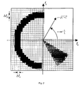
- FIG. 2 is a representational diagram of the calculations involved in calculating the ring-wedge data format using the bin-summing method of the invention
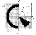
- FIG. 3 is a representational diagram of the calculations involved in calculating the ring-wedge data format using the mask-summing method of the invention
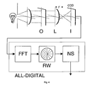
- FIG. 4 is a block diagram of the invention configured as a discrete Fourier spectral sampling system
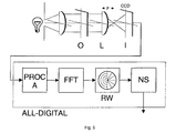
- FIG. 5 is a block diagram of the system/method of the invention as a discrete Fourier spectral sampling incorporating image preprocessing
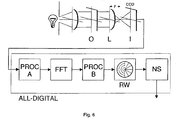
- FIG. 6 is a block diagram of the system/method of the invention as a discrete Fourier spectral sampling incorporating both image- and transform-domain preprocessing;
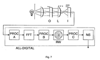
- FIG. 7 is a block diagram of the system/method of the invention as a discrete Fourier spectral sampling incorporating both image- and transform-domain preprocessor, as well as ring-wedge data postprocessing;
- FIG. 8 is a block diagram of the system/method of the invention tailored for image quality assessment using two separate ring-wedge data channels;
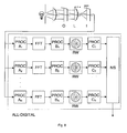
- FIG. 9 is a block diagram of the system/method of the invention as a multichannel discrete Fourier spectral sampling system incorporating different image- and transform-domain preprocessing, as well as ring-wedge data postprocessing for each of the channels;
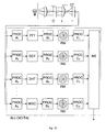
- FIG. 10 is a block diagram of the system/method of the invention as a multichannel sampling system incorporating different spatial transforms, image- and transform-domain preprocessing, and ring-wedge data postprocessing for each of the channels;
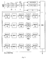
- FIG. 11 is a block diagram at the system of the invention as a multichannel sampling system incorporating various image domain features, as well as ring-wedge data calculated using different spatial transforms, image- and transform-domain preprocessing, and ring-wedge data postprocessing for each of the channels;
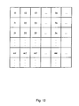
- FIG. 12 is a schematic representation of image tiling according to the invention.
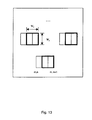
- FIG. 13 is a schematic representation of image rastering according to the invention.
- the present invention is of an automatic recognition system and method that has the capability to classify or recognize a wide variety of images grouped objectively by photointerpreters or other means.
- the invention can be configured for stand-alone use in a digital computer or incorporated as a tool-kit in a general image processing environment.
- the methods of the invention include spatial frequency sampling of an arbitrary image with selected pre-processing on one or several separate channels. These data are coupled into a neural network that is trained using a learning set of images that have been selected to span the base of classification or recognition.
- the preferred embodiment is an all-digital form of the ring-wedge photodetector (772-George) and incorporating two important variations.
- excellent results are obtained using a fully connected, three-layer, feed-forward configuration with sigmoidal activation functions.
- the invention can also include the use of nonlinear data processing such as rank ordering to provide robustness, edge extraction preprocessing, and error images as well as the original image.
- the invention comprises methods and software for calculating the ring-wedge data format from digital images.
- the methods and software are useful for constructing automatic pattern recognition systems that use pictorial imagery as input data. These applications include but are not limited to object recognition, image quality assessment, and image content classification.
- the methods can be applied generally to grayscale, color, and/or abstract images that may consist of an arbitrary number of data channels.
- the software also allows for the ring-wedge data format to be applied to any number of subimages taken from a single input image. In this way the software allows for systems to be constructed that use both spatial location and other image domain information with ring-wedge data.
- the data provided by the invention typically supply information about spatial frequency, however several transformations can be considered in addition to a discrete Fourier transform, including a discrete cosine transform and a Hadamard transform.
- the software, method, and system of the invention permits the inclusion of arbitrary image preprocessing and ring-wedge data post-processing, as well as various machine learning techniques through a modular design.
- the present invention comprises methods and software for calculating numerically the ring-wedge data format from digital images. This includes but is not limited to calculations involving a discrete Fourier transform and a discrete autocorrelation, as well as other discrete transforms such as a discrete cosine transform or a Hadamard transform, which provide a point-centered frame of reference on which to perform the ring-wedge sampling.
- the ring-wedge sampling is performed using the discrete Fourier transform (DFT) of the input digital imagery, defined as follows:
- DFT discrete Fourier transform
- f(n,m) is the digital array image with 0 ⁇ n ⁇ N, 0 ⁇ u ⁇ N, 0 ⁇ m ⁇ M, and 0 ⁇ v ⁇ M.
- the computer system can utilize both the phase as well as the amplitude of the DFT, ⁇ tilde over (F) ⁇ (u, v).
- This possibility produces interesting variations of the system.
- the following discussion presents a system that uses the absolute value of the transform, i.e,
- m j is the jth measurement over the sampling area to which each pixel's degree of membership is defined by the sampling geometry given by ⁇ tilde over (M) ⁇ j (u, v). The nature of this sampling geometry is described in the following paragraph.
- the ring-wedge detector geometry consists of semi-annular sampling areas on one half of the sampling plane and wedge-shaped sampling areas on the other.
- the separate samplings over 180 degrees are based on the use of the assertion that sampling be polar symmetric, as is the case with the amplitude transmittance of the DFT of a real valued input image.
- the radial sampling of the ring areas provides orientation-independent information about the distribution of spatial frequencies in the image while the angular sampling of the wedge areas provides scale-independent information about the orientations of those spatial frequencies.
- a direct approach is to treat the pixels in the sampling plane as isolated points and to calculate the ring-wedge measurements by summing together the contributions from each of the sample points within corresponding detector regions of the sampling geometry.
- F(f x ,f y ) is the continuous Fourier transform of the ideal continuous reconstruction of the sample's array image used as input to the system.
- the approximation is made by subdividing the Fourier plane on a regular rectangular grid with spacings of ⁇ f x and ⁇ f y in the f x and f y directions, respectively. For each rectangle covering a sampling region R j , employ the center point (u ⁇ f x ,v ⁇ f y ) and take the product of F(u ⁇ f x ,v ⁇ f y ) with the area of the rectangle, ⁇ f x ⁇ f y .
- ⁇ j is the angular distance from the f x axis to the leading edge of the jth detector region and ⁇ j is its angular width. Note that the radial extent of all of the wedge detectors is assumed to be equal, as given by ⁇ min and ⁇ max .
- the bin-summing method of the invention is preferably implemented as follows: First, the membership function for all of the sampling regions are defined according to the prescribed detector geometry and a given image size. Second, for each pixel location the polar coordinates are calculated according to its relative position from the detector center. The region in which the pixel belongs is then determined using these coordinates. This information can either be stored in a lookup table or used directly in calculating the ring-wedge samples. Last, for a particular image the magnitude of the DFT coefficient at each of the pixel locations is summed into its corresponding bin according to the determined region membership.
- a second execution stage is entered in which images are transformed and ring-wedge data calculated by a scan through the DFT coefficients.
- This two-stage approach to the method eliminates the need to calculate repetitively the polar coordinates of a each pixel location during the ring-wedge calculations of every image considered. When dealing with a large number of images, eliminating these extra coordinate calculations represents a substantial time savings over a single stage implementation of the bin-summing method.
- bin-summing can contain artifacts which compromise desired invariances and degrade recognition performance. This is especially true when dealing with small images. Bin-summing is most appropriate when working with images larger than 128 ⁇ 128 pixels. With smaller sized imagery, it is preferred to use an alternate method of the invention known as mask-summing, representationally illustrated in FIG. 3 .
- I(f x ,f y ) is an interpolating function
- the mask-summing method of the invention is preferably implemented as follows: First, the mask values for each of the sampling regions are calculated according to the prescribed detector geometry. For this step, an interpolating function is chosen and Eq. (10) is evaluated numerically.
- ring-edge data can be generated for a particles image by successively multiplying the DFT coefficients by each mask in the detector and summing over the affected pixels.
- FIG. 4 is a block diagram of the invention configured as a discrete Fourier spectral sampling system with the following components: O, input object; L, imaging lens; I, image sampling system; FFT, fast Fourier transform; RW, digital ring-wedge detector; and NS, neural-network software, hardware, or hybrid system.
- FIG. 5 is a block diagram of the system/method of the invention as a discrete Fourier spectral sampling incorporating image preprocessing, having the following components: O, input object; L, imaging lens; I, image sampling system; PROC A, image preprocessing; FFT, fast Fourier transform; RW, digital ring-wedge detector; and NS, neural-network software, hardware, or hybrid system.
- FIG. 6 is a block diagram of the system/method of the invention as a discrete Fourier spectral sampling incorporating both image- and transform-domain preprocessing, having the following components: O, input object; L, imaging lens; I, image sampling system; PROC A, image-domain preprocessing; PROC B, transform-domain preprocessing; FFT, fast Fourier transform; RW, digital ring-wedge detector; and NS, neural-network software, hardware, or hybrid system.
- O input object
- L imaging lens
- I image sampling system
- PROC A image-domain preprocessing
- PROC B transform-domain preprocessing
- FFT fast Fourier transform
- RW digital ring-wedge detector
- NS neural-network software, hardware, or hybrid system.
- FIG. 7 is a block diagram of the system/method of the invention as a discrete Fourier spectral sampling incorporating both image- and transform-domain preprocessor, as well as ring-wedge data postprocessing, having the following components: O, input object; L, imaging lens; I, image sampling system; PROC A, image-domain preprocessing; PROC B, transform-domain preprocessing; PROC C, ring-wedge data postprocessing; FFT, fast Fourier transform; RW digital ring-wedge detector; and NS, neural-network'software, hardware, or hybrid system.
- FIG. 8 is a block diagram of the system/method of the invention tailored for image quality assessment using two separate ring-wedge data channels.
- the first channel obtains ring-wedge data directly from the grayscale image.
- the second channel obtains ring-wedge data from a synthetic image generated from an edge enhancement of the input image.
- O input object
- L imaging lens
- I image sampling system
- EDGE image-domain preprocessing, edge enhancement
- FFT fast Fourier transform
- RW digital ring-wedge detector
- NS neural-network software, hardware, or hybrid system.
- FIG. 9 is a block diagram of the system/method of the invention as a multichannel discrete Fourier spectral sampling system incorporating different image- and transform-domain preprocessing, as well as ring-wedge data postprocessing for each of the channels, having the following components: O, input object; L, imaging lens; I, image sampling system; PROC A n , image-domain preprocessing for the nth channel; PROC B n , transform-domain preprocessing for the nth channel; PROC C n , ring-wedge data postprocessing for the nth channel; FFT, fast Fourier transform; RW, digital ring-wedge detector; and NS, neural-network software, hardware, or hybrid system.
- O input object
- L imaging lens
- I image sampling system
- PROC A n image-domain preprocessing for the nth channel
- PROC B n transform-domain preprocessing for the nth channel
- PROC C n ring-wedge data postprocessing for the n
- FIG. 10 is a block diagram of the system/method of the invention as a multichannel sampling system incorporating different spatial transforms, image- and transform-domain preprocessing, and ring-wedge data postprocessing for each of the channels, having the following components: O, input object; L, imaging lens; I, image sampling system; PROC A n , image-domain preprocessing for the nth channel; PROC B n , transform-domain preprocessing for the nth channel; PROC C n , ring-wedge data postprocessing for the nth channel; FFT, fast Fourier transform; DCT, discrete cosine transform; DHT, discrete Hadamard transform; MISC, other spatial transform; RW, digital ring-wedge detector; and NS, neural-network software, hardware, or hybrid system.
- O input object
- L imaging lens
- I image sampling system
- PROC A n image-domain preprocessing for the nth channel
- PROC B n transform-domain preprocessing for the n
- FIG. 11 is a block diagram at the system of the invention as a multichannel sampling system incorporating various image domain features, as well as ring-wedge data calculated using different spatial transforms, image- and transform-domain preprocessing, and ring-wedge data postprocessing for each of the channels, having the following components: O, input object; L, imaging lens; I, image sampling system; PROC A n , image-domain preprocessing for the nth channel; PROC B n , transform-domain preprocessing for the nth channel; PROC C n , ring-wedge data postprocessing for the nth channel; FFT, fast Fourier transform; DCT, discrete cosine transform; DHT, discrete Hadamard transform; MISC, other spatial transform; RW, digital ring-wedge detector; and NS, neural-network software, hardware, or hybrid system.
- O input object
- L imaging lens
- I image sampling system
- PROC A n image-domain preprocessing for the nth channel
- FIG. 12 illustrates image tiling according to the invention.
- the squares represent non-overlapping, identically shaped pixel regions.
- the ring-wedge data are calculated giving information about the local image content at each of the tiled locations.
- FIG. 13 illustrates image rastering according to the invention.
- the squares represent identically shaped pixel regions that overlap in a prescribed raster pattern.
- the ring-wedge data is calculated giving information about the local image content at each of the raster locations.
- the all-digital ring-wedge system of the invention incorporating a direct image channel as well, has demonstrated excellent results.
- a particular feature of the invention is that it can recognize faces over an angle of +/ ⁇ 45 degrees as the head is turned, even though the original training was done only with direct front views of the head.
- This general insensitivity to orientation is an important feature of the use of spatial transform sampling. More specifically, with proper assembly of the training set and in preparing the neural network, one can devise neural networks that are relatively insensitive to orientation, scale, contrast, or background clutter.
- the neural networks being generated can be regarded as new software products that are transportable and useful in remote computers.
- These completed neural networks can be thought of as extremely compact matched filters, like an identification card.
- the finished or trained neural network can be recorded on a chip or a magnetic strip and it is an extremely compact storage device—orders of magnitude fewer bytes, say, than the original image.
- This is best illustrated by a description of an entryway application.
- a person presents an identification card, such as a passport; and it has both a photograph and a fingerprint. For the fingerprint alone, typically, 8,000 bytes are required for storing the entire print.
- the neural network established by the present invention requires only 300 bytes. In effect, this trained neural network is an extremely efficient correlation filter. It provides a data compression of 8000/300, or better than 25 times. Accordingly, in the entryway application, it is preferable to include a magnetic strip or chip since this can be more easily handled in the computer than actually scanning the original thumbprint or face.
- the typical application is to classify images automatically. For example, an exhaustive listing is made of 24 desired images and one other. A three-layer neural network with 25 output neurons can then be trained using a set of learning images. It was found that 3 to 5 learning images are useful in each category in order to obtain classification in the high 95 to 100 percent accuracy level. Again, the trained neural network is a separate, identifiable product with its own utility. This software product can also be reproduced in a fast chip form in well-known methods. It is anticipated that the trained neural network in software or hardware will be widely used in wearable computer applications.
- Another important industrial application is the sorting of images into categories, e.g., for automating digital printing.
- the present invention has successfully segmented images into 16 to 400 separate sub-images.
- contents on a page as follows were accurately classified: type 1 photographs, line drawings, halftones, as well as color versus non-color.
Abstract
Description


Claims (51)


Priority Applications (1)
| Application Number | Priority Date | Filing Date | Title |
|---|---|---|---|
| US09/501,546 US6701029B1 (en) | 1999-11-08 | 2000-02-09 | Ring-wedge data analysis of digital images |
Applications Claiming Priority (2)
| Application Number | Priority Date | Filing Date | Title |
|---|---|---|---|
| US16399399P | 1999-11-08 | 1999-11-08 | |
| US09/501,546 US6701029B1 (en) | 1999-11-08 | 2000-02-09 | Ring-wedge data analysis of digital images |
Publications (1)
| Publication Number | Publication Date |
|---|---|
| US6701029B1 true US6701029B1 (en) | 2004-03-02 |
Family
ID=31720118
Family Applications (1)
| Application Number | Title | Priority Date | Filing Date |
|---|---|---|---|
| US09/501,546 Expired - Lifetime US6701029B1 (en) | 1999-11-08 | 2000-02-09 | Ring-wedge data analysis of digital images |
Country Status (1)
| Country | Link |
|---|---|
| US (1) | US6701029B1 (en) |
Cited By (11)
| Publication number | Priority date | Publication date | Assignee | Title |
|---|---|---|---|---|
| US20060013447A1 (en) * | 2004-07-16 | 2006-01-19 | Cross Match Technologies, Inc. | Hand-held personal identification analysis device and methods of use |
| US20060018519A1 (en) * | 2004-07-16 | 2006-01-26 | Cross Match Technologies, Inc. | Hand-held personal identification device with distributed control system |
| WO2009029757A1 (en) * | 2007-09-01 | 2009-03-05 | Global Rainmakers, Inc. | System and method for iris data acquisition for biometric identification |
| US20100000318A1 (en) * | 2006-06-07 | 2010-01-07 | Shuichi Inami | Method for determining cop generation factors for single-crystal silicon wafer |
| US8958606B2 (en) | 2007-09-01 | 2015-02-17 | Eyelock, Inc. | Mirror system and method for acquiring biometric data |
| US9002073B2 (en) | 2007-09-01 | 2015-04-07 | Eyelock, Inc. | Mobile identity platform |
| US9036871B2 (en) | 2007-09-01 | 2015-05-19 | Eyelock, Inc. | Mobility identity platform |
| US9117119B2 (en) | 2007-09-01 | 2015-08-25 | Eyelock, Inc. | Mobile identity platform |
| US9280706B2 (en) | 2011-02-17 | 2016-03-08 | Eyelock Llc | Efficient method and system for the acquisition of scene imagery and iris imagery using a single sensor |
| CN111161323A (en) * | 2019-12-31 | 2020-05-15 | 北京理工大学重庆创新中心 | Complex scene target tracking method and system based on correlation filtering |
| US11562046B2 (en) | 2018-11-26 | 2023-01-24 | Samsung Electronics Co., Ltd. | Neural network processor using dyadic weight matrix and operation method thereof |
Citations (1)
| Publication number | Priority date | Publication date | Assignee | Title |
|---|---|---|---|---|
| US5274714A (en) * | 1990-06-04 | 1993-12-28 | Neuristics, Inc. | Method and apparatus for determining and organizing feature vectors for neural network recognition |
-
2000
- 2000-02-09 US US09/501,546 patent/US6701029B1/en not_active Expired - Lifetime
Patent Citations (2)
| Publication number | Priority date | Publication date | Assignee | Title |
|---|---|---|---|---|
| US5274714A (en) * | 1990-06-04 | 1993-12-28 | Neuristics, Inc. | Method and apparatus for determining and organizing feature vectors for neural network recognition |
| US5465308A (en) * | 1990-06-04 | 1995-11-07 | Datron/Transoc, Inc. | Pattern recognition system |
Non-Patent Citations (2)
| Title |
|---|
| N. George, S. G. Wang, D. L. Venable, "Pattern recognition using the ring-wedge detector and neural-network software," SPIE, vol. 1134, p. 96, 1989.* * |
| Trygve Randen, John Hakon Husoy, "Filtering for texture classification: a comparative study", IEEE, vol. 21, No. 4, Apr. 1999. * |
Cited By (25)
| Publication number | Priority date | Publication date | Assignee | Title |
|---|---|---|---|---|
| US20060018519A1 (en) * | 2004-07-16 | 2006-01-26 | Cross Match Technologies, Inc. | Hand-held personal identification device with distributed control system |
| US20060013447A1 (en) * | 2004-07-16 | 2006-01-19 | Cross Match Technologies, Inc. | Hand-held personal identification analysis device and methods of use |
| US8978494B2 (en) | 2006-06-07 | 2015-03-17 | Sumco Corporation | Method for determining COP generation factors for single-crystal silicon wafer |
| DE112007001378B4 (en) * | 2006-06-07 | 2016-05-19 | Sumco Corporation | Method of determining COP generation factors for a silicon single crystal wafer |
| US20100000318A1 (en) * | 2006-06-07 | 2010-01-07 | Shuichi Inami | Method for determining cop generation factors for single-crystal silicon wafer |
| US8316727B2 (en) | 2006-06-07 | 2012-11-27 | Sumco Corporation | Method for determining COP generation factors for single-crystal silicon wafer |
| US8549937B2 (en) | 2006-06-07 | 2013-10-08 | Sumco Corporation | Method for determining COP generation factors for single-crystal silicon wafer |
| US9117119B2 (en) | 2007-09-01 | 2015-08-25 | Eyelock, Inc. | Mobile identity platform |
| US9626563B2 (en) | 2007-09-01 | 2017-04-18 | Eyelock Llc | Mobile identity platform |
| US9036871B2 (en) | 2007-09-01 | 2015-05-19 | Eyelock, Inc. | Mobility identity platform |
| US9055198B2 (en) | 2007-09-01 | 2015-06-09 | Eyelock, Inc. | Mirror system and method for acquiring biometric data |
| US9095287B2 (en) | 2007-09-01 | 2015-08-04 | Eyelock, Inc. | System and method for iris data acquisition for biometric identification |
| US8958606B2 (en) | 2007-09-01 | 2015-02-17 | Eyelock, Inc. | Mirror system and method for acquiring biometric data |
| US9192297B2 (en) | 2007-09-01 | 2015-11-24 | Eyelock Llc | System and method for iris data acquisition for biometric identification |
| US10296791B2 (en) | 2007-09-01 | 2019-05-21 | Eyelock Llc | Mobile identity platform |
| WO2009029757A1 (en) * | 2007-09-01 | 2009-03-05 | Global Rainmakers, Inc. | System and method for iris data acquisition for biometric identification |
| US9002073B2 (en) | 2007-09-01 | 2015-04-07 | Eyelock, Inc. | Mobile identity platform |
| US9633260B2 (en) | 2007-09-01 | 2017-04-25 | Eyelock Llc | System and method for iris data acquisition for biometric identification |
| US9792498B2 (en) | 2007-09-01 | 2017-10-17 | Eyelock Llc | Mobile identity platform |
| US9946928B2 (en) | 2007-09-01 | 2018-04-17 | Eyelock Llc | System and method for iris data acquisition for biometric identification |
| US10116888B2 (en) | 2011-02-17 | 2018-10-30 | Eyelock Llc | Efficient method and system for the acquisition of scene imagery and iris imagery using a single sensor |
| US9280706B2 (en) | 2011-02-17 | 2016-03-08 | Eyelock Llc | Efficient method and system for the acquisition of scene imagery and iris imagery using a single sensor |
| US11562046B2 (en) | 2018-11-26 | 2023-01-24 | Samsung Electronics Co., Ltd. | Neural network processor using dyadic weight matrix and operation method thereof |
| CN111161323A (en) * | 2019-12-31 | 2020-05-15 | 北京理工大学重庆创新中心 | Complex scene target tracking method and system based on correlation filtering |
| CN111161323B (en) * | 2019-12-31 | 2023-11-28 | 北京理工大学重庆创新中心 | Complex scene target tracking method and system based on correlation filtering |
Similar Documents
| Publication | Publication Date | Title |
|---|---|---|
| Qureshi et al. | A bibliography of pixel-based blind image forgery detection techniques | |
| Morse et al. | Muitiscale medial analysis of medical images | |
| JP4015362B2 (en) | Classification of fingerprints by spatial frequency components | |
| US20030161504A1 (en) | Image recognition system and recognition method thereof, and program | |
| EP2676224B1 (en) | Image quality assessment | |
| Dhivya et al. | Copy-move forgery detection using SURF feature extraction and SVM supervised learning technique | |
| US20070041638A1 (en) | Systems and methods for real-time object recognition | |
| US6701029B1 (en) | Ring-wedge data analysis of digital images | |
| JP2004078912A (en) | Method for positioning face in digital color image | |
| US11816946B2 (en) | Image based novelty detection of material samples | |
| JP4527885B2 (en) | Rotation correction and duplicate image identification by Fourier transform correlation | |
| Aneesh et al. | Optimal feature selection based on image pre-processing using accelerated binary particle swarm optimization for enhanced face recognition | |
| Diaz-Escobar et al. | A robust HOG-based descriptor for pattern recognition | |
| Savino et al. | Bleed-through cancellation in non-rigidly misaligned recto–verso archival manuscripts based on local registration | |
| Payne et al. | Image analysis techniques for holograms of dynamic oceanic particles | |
| Oravec et al. | Mobile ear recognition application | |
| JP2006252504A (en) | Pattern recognition device, pattern recognition method, pattern recognition program, and recording medium of pattern recognition program | |
| CN114120300A (en) | Picture correction method and device | |
| Nguyen et al. | Performance evaluation of real-time and scale-invariant LoG operators for text detection | |
| Fasquel et al. | A hybrid opto-electronic method for fast off-line handwritten signature verification | |
| Nautiyal et al. | An automated technique for criminal face identification using biometric approach | |
| Stafford et al. | Application of neural networks to computer-aided pathology detection in mammography | |
| Krishnan et al. | Web-based remote sensing image retrieval using multiscale and multidirectional analysis based on Contourlet and Haralick texture features | |
| Yang et al. | Image copy–move forgery detection based on sped-up robust features descriptor and adaptive minimal–maximal suppression | |
| Thakur et al. | A Review Paper on Image Forgery Detection In Image Processing |
Legal Events
| Date | Code | Title | Description |
|---|---|---|---|
| AS | Assignment |
Owner name: AUTOMATIC RECOGNITION & CONTROL, INC., NEW YORK Free format text: ASSIGNMENT OF ASSIGNORS INTEREST;ASSIGNORS:BERFANGER, DAVID M.;GEORGE, NICHOLAS;REEL/FRAME:010702/0182;SIGNING DATES FROM 20000204 TO 20000208 |
|
| STCF | Information on status: patent grant |
Free format text: PATENTED CASE |
|
| FPAY | Fee payment |
Year of fee payment: 4 |
|
| FPAY | Fee payment |
Year of fee payment: 8 |
|
| AS | Assignment |
Owner name: GEORGE, NICHOLAS, DR., NEW YORK Free format text: ASSIGNMENT OF ASSIGNORS INTEREST;ASSIGNOR:AUTOMATIC RECOGNITION & CONTROL, INC.;REEL/FRAME:029436/0228 Effective date: 20120312 |
|
| AS | Assignment |
Owner name: ARCOT, NEW YORK Free format text: ASSIGNMENT OF ASSIGNORS INTEREST;ASSIGNOR:GEORGE, NICHOLAS, DR.;REEL/FRAME:029492/0878 Effective date: 20120410 |
|
| FPAY | Fee payment |
Year of fee payment: 12 |