US6698271B1 - Process for reducing bias error in a vibrating structure sensor - Google Patents
Process for reducing bias error in a vibrating structure sensor Download PDFInfo
- Publication number
- US6698271B1 US6698271B1 US09/450,688 US45068899A US6698271B1 US 6698271 B1 US6698271 B1 US 6698271B1 US 45068899 A US45068899 A US 45068899A US 6698271 B1 US6698271 B1 US 6698271B1
- Authority
- US
- United States
- Prior art keywords
- pick
- primary
- vibrating structure
- output signal
- secondary pick
- Prior art date
- Legal status (The legal status is an assumption and is not a legal conclusion. Google has not performed a legal analysis and makes no representation as to the accuracy of the status listed.)
- Expired - Lifetime
Links
Images


Classifications
-
- G—PHYSICS
- G01—MEASURING; TESTING
- G01C—MEASURING DISTANCES, LEVELS OR BEARINGS; SURVEYING; NAVIGATION; GYROSCOPIC INSTRUMENTS; PHOTOGRAMMETRY OR VIDEOGRAMMETRY
- G01C19/00—Gyroscopes; Turn-sensitive devices using vibrating masses; Turn-sensitive devices without moving masses; Measuring angular rate using gyroscopic effects
- G01C19/56—Turn-sensitive devices using vibrating masses, e.g. vibratory angular rate sensors based on Coriolis forces
- G01C19/567—Turn-sensitive devices using vibrating masses, e.g. vibratory angular rate sensors based on Coriolis forces using the phase shift of a vibration node or antinode
Definitions
- This invention relates to a process for reducing bias error in a Vibrating Structure Sensor, particularly but not exclusively, suitable for use with a Vibrating Structure Gyroscope and to a Vibrating Structure Sensor.
- Vibrating structure sensors such as gyroscopes may be constructed using cylindrical or planar ring structures as the vibrating element. These are typically excited into a cos 2 ⁇ resonance mode. For a perfectly symmetric vibrating structure the cos 2 ⁇ mode actually exists as a degenerate pair of vibration modes at a mutual angle of 45°.
- the vibrations are shown schematically in FIGS. 1A and 1B.
- One of these modes (FIG. 1A) is excited as the carrier mode.
- Coriolis forces couple energy into the response mode (FIG. 1 B).
- the carrier mode vibration typically is maintained at a constant amplitude at the peak resonance frequency.
- Coriolis forces couple energy into the response mode.
- the amplitude of motion of the response mode is directly proportional to the applied rotation rate.
- the vibrating structure may be driven into resonance by various drive means including electromagnetic, electrostatic, piezo-electric, optical or thermal expansion.
- the induced motion may similarly be detected by various pick-off means, including electromagnetic, piezo-electric or optical.
- the orientation of the drives and pick-off means around the resonant structure are shown schematically in FIG. 2 .
- the primary drive means 1 excites the resonant carrier motion which is detected by the means 2 which is located at 90° to the primary drive means 1 . It is usual to operate the structure with the primary pick-off means output constant to maintain a constant carrier mode amplitude.
- the secondary pick-off means 3 is located 135° from the primary drive means 1 and is used to detect the response mode motion.
- the secondary pick-off signal output will be directly proportional to the applied rotation rate.
- An additional secondary drive means 4 positioned at 45° to the primary drive means 1 , may be employed to operate the sensor in a forced feedback or closed-loop mode. In this mode, the secondary pick-off output is nulled by applying a force on the secondary drive means 4 . The applied force is equal and opposite to the rotation induced Coriolis force and there is thus no resultant response mode motion.
- the performance of the sensor is characterized in terms of its scale factor and bias stability over the range of operating conditions. It is generally preferable to operate the sensor in a closed-loop configuration as this gives superior scale factor performance to the open-loop configuration. This is due to the fact that, with the response mode motion nulled, its dynamic behavior does not affect the rate response so variations in the quality factor, Q, over temperature will not affect the scale factor response.
- FIG. 3 shows a simplified block diagram of a conventional sensor control system operation.
- the system includes a primary drive amplifier 5 , a primary pick-off amplifier 6 , a secondary drive amplifier 7 and a secondary pick-off amplifier 8 .
- a primary drive input at 9 excites the carrier mode resonance and maintains a constant signal, and hence a constant amplitude of motion, at the primary pick-off output 10 for the primary resonance indicated at 11 .
- An applied rate, ⁇ at 12 will thus produce a Coriolis force which couples energy from the primary carrier mode into the secondary resonance or response mode 13 .
- this coupling is represented substantially by a multiplier 14 .
- the force F c is given by:
- PPO is the primary mode amplitude
- ⁇ p is the primary drive frequency
- K is a constant.
- This motion is detected and amplified by the secondary pick-off amplifier 8 .
- this signal amplitude is a direct measure of the applied rate.
- the secondary pick-off signal output 15 is fed back to the secondary drive input 16 .
- the secondary drive then applies a force driving to the response mode such that the secondary pick-off output 15 is nulled. In the absence of any errors, this force will be equal and opposite to the Coriolis force and thus there will be no net response mode motion.
- the amplitude of the applied force is proportional to the applied rate ⁇ .
- this error is represented by a coupling 17 between primary and secondary channels which adds a portion of the primary mode motion into the secondary pick-off output 15 .
- the response mode In order to maintain the pick-off output 15 at zero, the response mode must be driven such that the motion is equal and opposite to the error being summed in. The input to the response mode resonance is no longer zero so the secondary drive is not a true representation of the applied rate ⁇ .
- the secondary pick-off misalignment error, ⁇ r must be minimized. This is conveniently done as part of the vibrating structure balancing procedure and is achieved by adjusting the effective position of either the primary drive means 1 or the secondary pick-off means 3 .
- the balancing procedure is performed with the sensor effectively operating open loop. With the primary drive means 1 on resonance, the observed secondary pick-off output 15 will vary depending on the primary drive to carrier mode alignment angle.
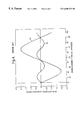
- the modelled secondary pick-off response is shown in FIG. 4 for a carrier mode frequency of 5 kHz with a frequency split of 0.2 Hz and a Q of 5000. These are typical resonator mode parameters for a known vibrating structure sensor.
- the response has been resolved into components which are in-phase (line 18 ) and in quadrature (line 19 ) with respect to the carrier mode motion. It is the in-phase component 18 which gives the rate output signal.
- Both in-phase 18 and quadrature 19 signals are zero when either mode is aligned to the drive.
- the amplitude of the signal variation with mode angle is dependent upon the level of frequency split and will tend to zero at all points for perfectly balanced modes. In practice, there will always be a residual frequency split and hence a variation in the secondary pick-off signal with mode angle.
- the effect is to shift the mean value of the in-phase response 18 .
- the in-phase bias is thus a function of both mode alignment and secondary pick-off alignment. Therefore, in order to correctly set the secondary pick-off alignment ( ⁇ r ⁇ 0), it is necessary to first accurately set the primary drive to carrier mode alignment.
- the quadrature signal 19 is insensitive to pick-off misalignment and is generally used as the error signal in setting the mode alignment during balancing.
- EP 0411489 B1 and GB 2272053 A describe the use of split-drive and pick-off transducers to perform the alignment. This is achieved by differentially adjusting the gains on the two halves of the transducer to shift the effective center. These techniques require the use of a non-standard transducer. For some vibrating structure gyro designs, the transducers are fixed on the resonator itself. Any non-standard transducer will adversely affect the dynamic symmetry between the two cos 2 ⁇ modes which may have a detrimental effect on the frequency split and hence on gyro performance.
- the fixed angular amount is 45°.
- a vibrating structure sensor having a vibrating structure, primary and secondary drive means for causing the vibrating structure, primary and secondary drive means for causing the vibrating structure to vibrate at resonance, and primary and secondary pick-off means for detecting vibration of the vibrating structure, which primary and secondary pick-off means are separated by a fixed angular amount with respect to the vibrating structure, characterized in that the vibrating structure is a substantially cylindrical or substantially planar ring- or hoop-like structure, and by including means for summing or subtracting a proportion of the primary pick-off means output signal into or from the secondary pick-off means output signal equivalent to reducing or increasing the secondary pick-off means angular separation from the primary drive means, by an amount sufficient to set the rate output signal from the vibrating structure to zero and thereby minimize bias error.
- FIGS. 1A and 1B diagramatically illustrate a carrier mode and response mode of vibration respectively for a conventional Vibrating Structure Sensor ring resonator excited into a cos 2 ⁇ resonance mode.
- FIG. 2 is a schematic illustration of the orientation of drive means and pick-off means around a conventional known vibrating resonant structure.
- FIG. 3 is a simplified block diagram of a conventional vibrating structure sensor control system operation not according to the present invention.
- FIG. 4 is a graphical representation of pick-off level against mode alignment angle showing the response of a sensor not according to the present invention resolved into in-phase and quadrature components.
- FIG. 5 is a graphic display of pick-off signal against mode alignment angle similar to that of FIG. 4 but showing the effect of introducing a 1° degree secondary pick-off alignment error for the same vibrating structure parameters as in FIG. 4 .
- FIG. 6 is a graphic representation showing the secondary drive in-phase and quadrature components as a function of mode angle alignment for the same parameters as in FIG. 4 but according to the process of the present invention.
- FIG. 7 is a block diagram of the process according to the present invention for reducing bias error incorporating error compensation.
- the process of the present invention for reducing bias error is suitable for use with a vibrating structure sensor having a substantially cylindrical or substantially planar ring- or hoop-like vibrating structure, primary and secondary drive means 1 , 4 for causing the vibrating structure to vibrate at resonance and primary and secondary pick-off means 2 , 3 , for detecting vibration of the vibrating structure.
- the means 1 , 2 , 3 , 4 are arranged as shown in FIG. 2 of the accompanying drawings and the primary and secondary pick-off means 2 , 3 are separated by a fixed angular amount, preferably 45°, with respect to the vibrating structure.
- the open-loop modeling of the pick-off means responses may be extended to include the effect of nulling the secondary pick-off means output 10 .
- the in-phase and quadrature components of the secondary drive means 4 become of importance.
- FIG. 6 of the accompanying drawings shows the secondary drive components as a function of mode angle alignment for the same vibrating structure mode parameters as for the non-inventive FIG. 4 example with a 1° error.
- the quadrature drive has a functional form or line 19 a similar to the open loop quadrature pick-off signal behavior 19 of FIG. 4 .
- the in-phase response component line 18 a is dramatically different and exhibits no mode angle sensitivity.
- the fixed offset level is determined by the magnitude of ⁇ r . Performing the secondary pick-off adjustment with the sensor operating in a closed-loop configuration therefore enables this source of error to be trimmed out without requiring the modes accurately to be aligned.
- the primary pick-off means 2 is located 45° around from the secondary pick-off means 3 .
- the effective center point of the secondary pick-off means 2 may therefore be shifted in this direction by summing a proportion of the primary signal into the secondary.
- the vibrating structure motion at the point 45° in the other direction from the secondary pick-off means 3 will be 180° out of phase with the motion at the primary pick-off means 2 but otherwise identical.
- the effective position of the secondary pick-off means 3 can thus be shifted in the other direction by subtracting a proportion of the primary pick-off.
- a proportion of the primary pick-off means output signal 10 is summed into the secondary pick-off means output signal 15 or a proportion of the primary pick-off means output signal 10 is subtracted from the secondary pick-off means output signal 15 equivalent to reducing or increasing the angular separation of the secondary pick-off means 3 from the primary drive means 1 by an amount sufficient to set the rate output signal from the vibrating structure to zero and thereby minimize bias error.
- FIG. 7 This compensation system according to the invention can be incorporated into the system block diagram as shown in FIG. 7 which is basically similar to the block diagram of FIG. 3 and in which like parts will be given like reference numerals to those of FIG. 3 and will not therefore be described in further detail.
- means for adjusting the secondary pick-off means 3 effective angular separation from the primary drive means 1 by an amount sufficient to set the rate output signal from the vibrating structure to zero and thereby minimize bias error is provided between the primary pick-off output 10 and the secondary pick-off output 15 .
- This latter means is a trim means 20 whereby the secondary pick-off angle trim is adjusted to set the rate output signal to zero. This results in no net force being applied to excite the response mode in the absence of rotation.
- the force applied to the vibrating structure is now an accurate representation of the applied rate.
- the present invention has inherent advantages over those described in EP 0411489 B1 and GB 2272053 A which require the use of non-standard transducers for the pick-off means.
- the present invention can use standard transducers and thus maintains a symmetry consistent with the Cos 2 ⁇ mode dynamics.
- Use of standard modules is also advantageous as any scaling changes such as temperature dependent gains, will be largely identical for all modules and the resultant errors will therefore tend to cancel out.
Landscapes
- Physics & Mathematics (AREA)
- Engineering & Computer Science (AREA)
- General Physics & Mathematics (AREA)
- Radar, Positioning & Navigation (AREA)
- Remote Sensing (AREA)
- Gyroscopes (AREA)
Abstract
Description

Claims (3)
Applications Claiming Priority (1)
| Application Number | Priority Date | Filing Date | Title |
|---|---|---|---|
| PCT/GB1998/002057 WO1999002942A2 (en) | 1997-07-11 | 1998-07-13 | Process for reducing bias error in a vibrating structure sensor |
Related Parent Applications (1)
| Application Number | Title | Priority Date | Filing Date |
|---|---|---|---|
| PCT/GB1998/002057 Continuation WO1999002942A2 (en) | 1997-07-11 | 1998-07-13 | Process for reducing bias error in a vibrating structure sensor |
Publications (1)
| Publication Number | Publication Date |
|---|---|
| US6698271B1 true US6698271B1 (en) | 2004-03-02 |
Family
ID=31726465
Family Applications (1)
| Application Number | Title | Priority Date | Filing Date |
|---|---|---|---|
| US09/450,688 Expired - Lifetime US6698271B1 (en) | 1998-07-13 | 1999-11-30 | Process for reducing bias error in a vibrating structure sensor |
Country Status (1)
| Country | Link |
|---|---|
| US (1) | US6698271B1 (en) |
Cited By (11)
| Publication number | Priority date | Publication date | Assignee | Title |
|---|---|---|---|---|
| US20040237626A1 (en) * | 2001-08-09 | 2004-12-02 | Challoner A. Dorian | Cloverleaf microgyroscope with electrostatic alignment and tuning |
| US20060174684A1 (en) * | 2003-07-04 | 2006-08-10 | Uwe Betz | Method for aligning a rotation rate sensor |
| US20070240508A1 (en) * | 2006-04-18 | 2007-10-18 | Watson William S | Vibrating inertial rate sensor utilizing skewed drive or sense elements |
| US20070256495A1 (en) * | 2006-04-18 | 2007-11-08 | Watson William S | Vibrating Inertial Rate Sensor Utilizing Split or Skewed Operational Elements |
| US7895893B2 (en) | 2005-09-12 | 2011-03-01 | Vdo Automotive Ag | Method for operating a vibrating gyroscope and sensor arrangement |
| WO2012067534A1 (en) | 2010-11-19 | 2012-05-24 | Общество С Ограниченной Ответственностью "Инналабс" | Axially symmetrical coriolis vibratory gyroscope (variants) |
| US20130160546A1 (en) * | 2011-12-26 | 2013-06-27 | Samsung Electro-Mechanics Co., Ltd. | Gyro sensor drive circuit, gyro sensor system and method for driving gyro sensor |
| EP2696169A2 (en) | 2012-08-07 | 2014-02-12 | Innalabs Limited | Force-rebalance coriolis vibratory gyroscope |
| US20150192415A1 (en) * | 2014-01-03 | 2015-07-09 | The Boeing Company | Gyro quadrature stabalization with demodulation phase error nulling |
| US10161751B2 (en) | 2014-02-26 | 2018-12-25 | Sumitomo Precision Products Co., Ltd. | Vibration-type angular rate sensor |
| CN111536994A (en) * | 2020-04-29 | 2020-08-14 | 中国人民解放军国防科技大学 | Resonant micro gyroscope multi-mode cooperative control method and system and resonant micro gyroscope |
Citations (7)
| Publication number | Priority date | Publication date | Assignee | Title |
|---|---|---|---|---|
| US4038876A (en) * | 1976-03-04 | 1977-08-02 | Systron Donner Corporation | Acceleration error compensated attitude sensing and control apparatus and method |
| GB2251072A (en) | 1990-12-22 | 1992-06-24 | British Aerospace | Piezo-electric rate sensors |
| US5218867A (en) * | 1989-07-29 | 1993-06-15 | British Aerospace Public Limited Company | Single axis attitude sensor |
| GB2272053A (en) * | 1992-11-03 | 1994-05-04 | Marconi Gec Ltd | A solid state vibrational gyroscope |
| US5629472A (en) * | 1992-04-24 | 1997-05-13 | British Aerospace Public Limited Company | Method of minimizing bias and achieving mode alignment by trimming a vibrating rate sensor |
| US5703292A (en) * | 1994-03-28 | 1997-12-30 | The Charles Stark Draper Laboratory, Inc. | Sensor having an off-frequency drive scheme and a sense bias generator utilizing tuned circuits |
| US6155115A (en) * | 1991-01-02 | 2000-12-05 | Ljung; Per | Vibratory angular rate sensor |
-
1999
- 1999-11-30 US US09/450,688 patent/US6698271B1/en not_active Expired - Lifetime
Patent Citations (7)
| Publication number | Priority date | Publication date | Assignee | Title |
|---|---|---|---|---|
| US4038876A (en) * | 1976-03-04 | 1977-08-02 | Systron Donner Corporation | Acceleration error compensated attitude sensing and control apparatus and method |
| US5218867A (en) * | 1989-07-29 | 1993-06-15 | British Aerospace Public Limited Company | Single axis attitude sensor |
| GB2251072A (en) | 1990-12-22 | 1992-06-24 | British Aerospace | Piezo-electric rate sensors |
| US6155115A (en) * | 1991-01-02 | 2000-12-05 | Ljung; Per | Vibratory angular rate sensor |
| US5629472A (en) * | 1992-04-24 | 1997-05-13 | British Aerospace Public Limited Company | Method of minimizing bias and achieving mode alignment by trimming a vibrating rate sensor |
| GB2272053A (en) * | 1992-11-03 | 1994-05-04 | Marconi Gec Ltd | A solid state vibrational gyroscope |
| US5703292A (en) * | 1994-03-28 | 1997-12-30 | The Charles Stark Draper Laboratory, Inc. | Sensor having an off-frequency drive scheme and a sense bias generator utilizing tuned circuits |
Cited By (19)
| Publication number | Priority date | Publication date | Assignee | Title |
|---|---|---|---|---|
| US7159441B2 (en) * | 2001-08-09 | 2007-01-09 | The Boeing Company | Cloverleaf microgyroscope with electrostatic alignment and tuning |
| US20040237626A1 (en) * | 2001-08-09 | 2004-12-02 | Challoner A. Dorian | Cloverleaf microgyroscope with electrostatic alignment and tuning |
| US20060174684A1 (en) * | 2003-07-04 | 2006-08-10 | Uwe Betz | Method for aligning a rotation rate sensor |
| US7188522B2 (en) * | 2003-07-04 | 2007-03-13 | Siemens Aktiengesellschaft | Method for aligning a rotation rate sensor |
| US7895893B2 (en) | 2005-09-12 | 2011-03-01 | Vdo Automotive Ag | Method for operating a vibrating gyroscope and sensor arrangement |
| US20070240508A1 (en) * | 2006-04-18 | 2007-10-18 | Watson William S | Vibrating inertial rate sensor utilizing skewed drive or sense elements |
| US7617727B2 (en) | 2006-04-18 | 2009-11-17 | Watson Industries, Inc. | Vibrating inertial rate sensor utilizing split or skewed operational elements |
| US20070256495A1 (en) * | 2006-04-18 | 2007-11-08 | Watson William S | Vibrating Inertial Rate Sensor Utilizing Split or Skewed Operational Elements |
| US7526957B2 (en) | 2006-04-18 | 2009-05-05 | Watson Industries, Inc. | Vibrating inertial rate sensor utilizing skewed drive or sense elements |
| EP3009792A1 (en) | 2010-11-19 | 2016-04-20 | Innalabs Limited | Gyroscope |
| WO2012067534A1 (en) | 2010-11-19 | 2012-05-24 | Общество С Ограниченной Ответственностью "Инналабс" | Axially symmetrical coriolis vibratory gyroscope (variants) |
| US20130160546A1 (en) * | 2011-12-26 | 2013-06-27 | Samsung Electro-Mechanics Co., Ltd. | Gyro sensor drive circuit, gyro sensor system and method for driving gyro sensor |
| EP2696169A2 (en) | 2012-08-07 | 2014-02-12 | Innalabs Limited | Force-rebalance coriolis vibratory gyroscope |
| US9157739B1 (en) * | 2012-08-07 | 2015-10-13 | Innalabs Limited | Force-rebalance coriolis vibratory gyroscope |
| US20150192415A1 (en) * | 2014-01-03 | 2015-07-09 | The Boeing Company | Gyro quadrature stabalization with demodulation phase error nulling |
| US9605964B2 (en) * | 2014-01-03 | 2017-03-28 | The Boeing Company | Gyro quadrature stabalization with demodulation phase error nulling |
| US10161751B2 (en) | 2014-02-26 | 2018-12-25 | Sumitomo Precision Products Co., Ltd. | Vibration-type angular rate sensor |
| CN111536994A (en) * | 2020-04-29 | 2020-08-14 | 中国人民解放军国防科技大学 | Resonant micro gyroscope multi-mode cooperative control method and system and resonant micro gyroscope |
| CN111536994B (en) * | 2020-04-29 | 2021-09-24 | 中国人民解放军国防科技大学 | Resonant micro gyroscope multi-mode cooperative control method and system and resonant micro gyroscope |
Similar Documents
| Publication | Publication Date | Title |
|---|---|---|
| US7240533B2 (en) | Method for reducing bias error in a vibrating structure gyroscope | |
| EP1421331B1 (en) | Method for electrostatically aligning and tuning a microgyroscope | |
| EP1012538B1 (en) | Process for reducing bias error in a vibrating structure sensor | |
| EP1417455B1 (en) | Microgyroscope with electronic alignment and tuning | |
| US6282958B1 (en) | Angular rate sensor | |
| EP2092272B1 (en) | Improvements in or relating to a gyroscope | |
| US6439051B2 (en) | Vibrators, vibratory gyroscopes, devices for measuring a linear acceleration and a method of measuring a turning angular rate | |
| US6805007B2 (en) | Vibratory sensor operating as a rate gyro about two axes and as a rate integrating gyro about the third one | |
| US20040144174A1 (en) | Vibratory gyroscopic rate sensor | |
| US6698271B1 (en) | Process for reducing bias error in a vibrating structure sensor | |
| US20040199347A1 (en) | Multi stage control architecture for error suppression in micromachined gyroscopes | |
| EP0736749B1 (en) | Method for actively balancing a vibrating gyroscope sensing element | |
| US20050092084A1 (en) | Rate sensing device | |
| EP1944574A1 (en) | Improvements in or relating to a gyroscope | |
| JPH09210693A (en) | Method for adjusting vibration of shell type vibrator |
Legal Events
| Date | Code | Title | Description |
|---|---|---|---|
| AS | Assignment |
Owner name: BRITISH AEROSPACE PUBLIC LIMITED COMPANY, GREAT BR Free format text: ASSIGNMENT OF ASSIGNORS INTEREST;ASSIGNORS:FELL, CHRISTOPHER PAUL;HOPKIN, IAN DAVID;TOWNSEND, KEVIN;REEL/FRAME:010423/0120 Effective date: 19991109 |
|
| AS | Assignment |
Owner name: BAE SYSTEMS PLC, GREAT BRITAIN Free format text: CHANGE OF NAME;ASSIGNOR:BRITISH AEROSPACE PUBLIC LIMITED COMPANY;REEL/FRAME:011195/0643 Effective date: 20000505 |
|
| STCF | Information on status: patent grant |
Free format text: PATENTED CASE |
|
| CC | Certificate of correction | ||
| FEPP | Fee payment procedure |
Free format text: PAYOR NUMBER ASSIGNED (ORIGINAL EVENT CODE: ASPN); ENTITY STATUS OF PATENT OWNER: LARGE ENTITY |
|
| FPAY | Fee payment |
Year of fee payment: 4 |
|
| AS | Assignment |
Owner name: ATLANTIC INERTIAL SYSTEMS LIMITED, UNITED KINGDOM Free format text: ASSIGNMENT OF ASSIGNORS INTEREST;ASSIGNOR:BAE SYSTEMS PLC;REEL/FRAME:019910/0387 Effective date: 20070820 |
|
| AS | Assignment |
Owner name: BNP PARIBAS, ILLINOIS Free format text: PATENT SECURITY AGREEMENT;ASSIGNOR:ATLANTIC INERTIAL SYSTEMS LIMITED;REEL/FRAME:019930/0508 Effective date: 20070820 |
|
| AS | Assignment |
Owner name: ATLANTIC INERTIAL SYSTEMS LIMITED, UNITED KINGDOM Free format text: RELEASE BY SECURED PARTY;ASSIGNOR:BNP PARIBAS;REEL/FRAME:023679/0646 Effective date: 20091221 |
|
| FPAY | Fee payment |
Year of fee payment: 8 |
|
| FPAY | Fee payment |
Year of fee payment: 12 |