US6693399B2 - Servo-control devices, in particular for an aircraft flight control actuator - Google Patents

Servo-control devices, in particular for an aircraft flight control actuator Download PDF

Info

Publication number
US6693399B2
US6693399B2 US09/884,176 US88417601A US6693399B2 US 6693399 B2 US6693399 B2 US 6693399B2 US 88417601 A US88417601 A US 88417601A US 6693399 B2 US6693399 B2 US 6693399B2
Authority
US
United States
Prior art keywords
servo
control
force
determining
transfer function
Prior art date
Legal status (The legal status is an assumption and is not a legal conclusion. Google has not performed a legal analysis and makes no representation as to the accuracy of the status listed.)
Expired - Lifetime
Application number
US09/884,176
Other versions
US20020038841A1 (en
Inventor
Geneviève Silvestro
Current Assignee (The listed assignees may be inaccurate. Google has not performed a legal analysis and makes no representation or warranty as to the accuracy of the list.)
Goodrich Control Systems
Original Assignee
TRW Systemes Aeronautiques Civils SAS
Priority date (The priority date is an assumption and is not a legal conclusion. Google has not performed a legal analysis and makes no representation as to the accuracy of the date listed.)
Filing date
Publication date
Application filed by TRW Systemes Aeronautiques Civils SAS filed Critical TRW Systemes Aeronautiques Civils SAS
Assigned to TRW SYSTEMES AERONAUTIQUES CIVILS reassignment TRW SYSTEMES AERONAUTIQUES CIVILS ASSIGNMENT OF ASSIGNORS INTEREST (SEE DOCUMENT FOR DETAILS). Assignors: SILVESTRO, GENEVIEVE
Publication of US20020038841A1 publication Critical patent/US20020038841A1/en
Assigned to GOODRICH CONTROL SYSTEMS reassignment GOODRICH CONTROL SYSTEMS ASSIGNMENT OF ASSIGNORS INTEREST (SEE DOCUMENT FOR DETAILS). Assignors: TRW SYSTEMES AERONAUTIQUES CIVILS
Application granted granted Critical
Publication of US6693399B2 publication Critical patent/US6693399B2/en
Anticipated expiration legal-status Critical
Expired - Lifetime legal-status Critical Current

Links

Images

Classifications

    • GPHYSICS
    • G05CONTROLLING; REGULATING
    • G05DSYSTEMS FOR CONTROLLING OR REGULATING NON-ELECTRIC VARIABLES
    • G05D1/00Control of position, course, altitude or attitude of land, water, air or space vehicles, e.g. using automatic pilots
    • G05D1/08Control of attitude, i.e. control of roll, pitch, or yaw
    • G05D1/0808Control of attitude, i.e. control of roll, pitch, or yaw specially adapted for aircraft
    • G05D1/0816Control of attitude, i.e. control of roll, pitch, or yaw specially adapted for aircraft to ensure stability
    • G05D1/0825Control of attitude, i.e. control of roll, pitch, or yaw specially adapted for aircraft to ensure stability using mathematical models
    • GPHYSICS
    • G05CONTROLLING; REGULATING
    • G05BCONTROL OR REGULATING SYSTEMS IN GENERAL; FUNCTIONAL ELEMENTS OF SUCH SYSTEMS; MONITORING OR TESTING ARRANGEMENTS FOR SUCH SYSTEMS OR ELEMENTS
    • G05B19/00Programme-control systems
    • G05B19/02Programme-control systems electric
    • G05B19/18Numerical control [NC], i.e. automatically operating machines, in particular machine tools, e.g. in a manufacturing environment, so as to execute positioning, movement or co-ordinated operations by means of programme data in numerical form
    • G05B19/19Numerical control [NC], i.e. automatically operating machines, in particular machine tools, e.g. in a manufacturing environment, so as to execute positioning, movement or co-ordinated operations by means of programme data in numerical form characterised by positioning or contouring control systems, e.g. to control position from one programmed point to another or to control movement along a programmed continuous path
    • GPHYSICS
    • G05CONTROLLING; REGULATING
    • G05DSYSTEMS FOR CONTROLLING OR REGULATING NON-ELECTRIC VARIABLES
    • G05D15/00Control of mechanical force or stress; Control of mechanical pressure
    • G05D15/01Control of mechanical force or stress; Control of mechanical pressure characterised by the use of electric means

Definitions

  • the present invention relates to servo-control devices, in particular for an aircraft flight control actuator.
  • a preferred application lies with devices for servo-controlling position.
  • the invention is also advantageously applicable to devices for servo-controlling force.
  • a position servo-control device for a flight control actuator comprises a servo-control loop which includes compensation means disposed in the loop upstream from the servo-controlled system and performing filtering, in particular at resonant frequencies for movements of the mechanical part(s) actuated by said system.
  • a problem encountered with such a servo-control device lies in that no account is taken of the forces which act on the mechanical parts being actuated.
  • Document EP 0 897 111 discloses a mechanical test machine comprising a servo-control device making it possible to control a load exerted on a sample of material under test.
  • the servo-control device has means for determining an error that is characteristic of the difference between the theoretical reference force and a variable that depends on the real applied maximum and minimum forces.
  • Document FR 2 660 705 describes a device for servo-controlling the force exerted on the piston of a hydraulic actuator. That device comprises a servo-control loop that takes account of an error which is characteristic of the difference between the real force applied and a reference force, and an additional loop that takes the speed of the piston into account.
  • An object of the invention is to provide a position servo-control device of this kind which is particularly simple and reliable.
  • the invention provides a servo-control device comprising at least one servo-control loop which receives a servo-control signal as input and whose output acts on an element to be servo-controlled, said device comprising means for determining a parameter characterizing the real force generated by the servo-control, the device also including a loop having means for determining an error characteristic of the difference between said parameter characterizing the real force and a parameter characterizing an acceptable theoretical force which is a function of the servo-control signal, and also means for correcting the processing of the servo-control loop as a function of said error.
  • Such a device which can be a position servo-control device, or a force servo-control device, presents the advantage of providing very high performance force control.
  • the means for determining the error comprise determination means for determining a parameter characterizing the acceptable theoretical force on the basis of a reference model
  • an actuator controlled by the servo-control loop is of the hydraulic type and the reference model is a force/signal transfer function for controlling flow rate;
  • the determination means comprise means for implementing a transfer function having the same appearance as a transfer function for determining the parameter characterizing the real force, except in the vicinity of at least one resonant frequency of said force;
  • F ref Q ref ks ( 1 2 ⁇ ⁇ ⁇ ⁇ f 0 ) 2 ⁇ s 2 + 2 ⁇ x ⁇ ⁇ 2 ⁇ ⁇ ⁇ ⁇ f 0 ⁇ s + 1 ⁇ B ⁇ ( s )
  • s represents the Laplacian
  • f0 is equal to or close to a resonant frequency
  • being an attenuation factor having magnitude of about 0.7 to 1
  • k being a gain factor
  • B(s) being a filter function
  • the invention also advantageously provides a hydraulic servo-control device constituted by a device of the above-specified type.
  • the invention also provides a servo-control device for a flight control actuator or a test actuator, the device being constituted by a device of the above-specified type.
  • FIG. 1 is a block diagram of a device constituting a possible embodiment of the invention
  • FIG. 2 is a diagram of a hydraulic servo-control actuator
  • FIGS. 3 a to 3 c are three graphs showing different transfer functions that can be used with a device of the type shown in FIG. 1 .
  • the device shown in FIG. 1 comprises a servo-control loop 1 which has a servo-controlled system 3 , and compensation means 2 which are disposed in the loop upstream from the servo-controlled system 3 .
  • Subtracter means at the inlet of the loop receive a control signal C and subtract therefrom a signal “y M ” output by the loop so as to generate an error signal, said means being referenced 4 .
  • the signal “y M ” is a signal characteristic of the controlled position or force, whereas the signal C is a signal of the same nature characterizing the reference position or force.
  • FIG. 1 also shows a filter 5 whose input receives an unfiltered control signal and which outputs the signal C.
  • the compensation means 2 receive the error signal output by the subtracter means 4 and apply filtering thereto, amongst other things at frequencies which are resonant frequencies for movements of the mechanical parts controlled by the actuator (transfer function C(s)).
  • the servo-controlled system 3 also includes a loop 6 which calculates the difference between a real force F p corresponding to the signal y M output by the loop 3 and an authorized force F M which is determined as a function of the signal Cr output by the compensation means 2 .
  • the module for determining the authorized mechanical F M is referenced 7 .
  • This model is selected to correspond substantially to the real force behavior of the servo-control in the absence of the loop 6 , significantly modified to avoid or limit mechanical force resonances.
  • the subtracter means of the loop 6 are referenced 9 .
  • the output signal from these subtracter means 9 can be subject where appropriate to compensation treatment (module 10 whose transfer function C F (s) can be a simple gain function, for example), the correction signal EPS r output from this processing being added to the signal Cr (means 11 ).
  • the resulting correct signal Q (for hydraulic servo-control, Q is a flow rate control signal), is injected as an input to the actuator 3 a.
  • the real force F P can be determined by a pressure sensor provided for this purpose.
  • the actuator 3 a can comprise two modules implementing two successive transfer functions F/Q and then Y/F, the signal characteristic of the real force F P being the signal output from the module corresponding to the first transfer function F/Q.
  • the loop 6 made in this way serves to stabilize the force behavior generated by the servo-control.
  • An actuator or servo-control can be represented diagrammatically as shown in FIG. 2 by a hydraulic stiffness Rh, a hydraulic damping coefficient Cvh, a surface area S, a flow rate Q (e.g. controlled by means of an electrical input), pressures Pa and Pb in two respective hydraulic chambers, and with the assembly being loaded by a mass M via a stiffness Rm and a mechanical damping coefficient Cvm.
  • the displacement of the actuator rod is written y, that of the mass M z, and the force generated by the actuator being written F.
  • Equation [2] can then be expressed as a function of [4] as follows:
  • F Q R h + C vn ⁇ s Ss ⁇ ( 1 + R m + C vm ⁇ s + Ms 2 R m + C vm ⁇ s ) ⁇ Ms 2 ⁇ ( R h + C vh ⁇ s ) ) [ 5 ]
  • F Q ( R h + C vh ⁇ s ) ⁇ ( R m + C vm ⁇ s ) ⁇ Ms 2 Ss ⁇ ( C vh + C vm ) ⁇ Ms 3 + ( M ⁇ ( R h + R m ) + C vh ⁇ C vm ) ⁇ s 2 + ( R h ⁇ C vm + R m ⁇ C vh ) ⁇ s + R h ⁇ R m ) [ 6 ]
  • F Q Ms ⁇ ( R h ⁇ R
  • the position or force transfer y/Q can thus be resolved as a first transfer function F/Q given by [7] followed by a second equation y/F whose transfer function is given by [4], position servo-control being performed on the complete system at y/Q.
  • the resonance leads to peaks where force is very high, particularly whenever there is a change of control sign.
  • Position transfer y/F has the appearance shown in FIG. 3 b , with a drop of gain at frequency F2 given mainly by 1 2 ⁇ ⁇ ⁇ R m M
  • the ratio between the frequencies F1 and F2 is R h R h + R m
  • F1 is always smaller than F2.
  • a model for use in the force control loop 6 can be deduced from knowledge of the linear transfer function F/Q.
  • the transfer function P F (s) corresponding to this model can be selected so as to correspond to F/Q at very low frequencies and eliminate as much as possible the resonance around F1.
  • This transfer function is shown in FIG. 3 c where it is superposed on the transfer function of FIG. 3 a (dashed line) and it is obtained on the basis of a priori knowledge concerning the structure of F/Q, specifically a pure derivative term in the numerator, and a second order of natural angular frequency f0 which is not necessarily exactly equal to F1 (for example, an error of 20% relative to F1 is completely acceptable, with a damping factor ⁇ which, for example, can be of magnitude lying in the range 0.7 to 1 and which serves to eliminate the overload).
  • B(s) represents a filter term which in simplified form can be taken to be equal to 1;
  • k is a gain term which corresponds to the transfer function C F (s).
  • the devices proposed by the invention can advantageously be used in servo-control devices having a plurality of servo-control loops in parallel.
  • the invention is easily implemented on conventional servo-control devices in which the various servo-control loops are synchronized by means of force measurements.
  • one of the major advantages of the invention lies in that it enables operation of the main servo-control loop (loop 1 in FIG. 1) to continue even if the correction loop for taking force into account (loop 6 in FIG. 1) should fail.

Landscapes

  • Engineering & Computer Science (AREA)
  • Physics & Mathematics (AREA)
  • General Physics & Mathematics (AREA)
  • Automation & Control Theory (AREA)
  • Pure & Applied Mathematics (AREA)
  • Mathematical Physics (AREA)
  • Mathematical Optimization (AREA)
  • Mathematical Analysis (AREA)
  • Aviation & Aerospace Engineering (AREA)
  • Radar, Positioning & Navigation (AREA)
  • Remote Sensing (AREA)
  • Algebra (AREA)
  • Human Computer Interaction (AREA)
  • Manufacturing & Machinery (AREA)
  • Feedback Control In General (AREA)

Abstract

The invention relates to a servo-control device comprising at least one servo-control loop which receives a servo-control signal as input and whose output acts on an element to be servo-controlled, said device comprising means for determining a parameter characterizing the real force generated by the servo-control, the device also including a loop having means for determining an error characteristic of the difference between said parameter characterizing the real force and a parameter characterizing an acceptable theoretical force which is a function of the servo-control signal, and also means for correcting the processing of the servo-control loop as a function of said error. The means for determining the error make use of a reference model which is advantageously a transfer function relating force to a flow rate control signal.

Description

The present invention relates to servo-control devices, in particular for an aircraft flight control actuator.
A preferred application lies with devices for servo-controlling position.
The invention is also advantageously applicable to devices for servo-controlling force.
BACKGROUND OF THE INVENTION
Conventionally, a position servo-control device for a flight control actuator comprises a servo-control loop which includes compensation means disposed in the loop upstream from the servo-controlled system and performing filtering, in particular at resonant frequencies for movements of the mechanical part(s) actuated by said system.
A problem encountered with such a servo-control device lies in that no account is taken of the forces which act on the mechanical parts being actuated.
Unfortunately, these forces can be particularly large.
In various technical fields, in particular in fields very distant from aircraft flight control actuators, various servo-controlled systems have been proposed for improving control of the force exerted on the mechanical parts that are actuated.
Document EP 0 897 111 discloses a mechanical test machine comprising a servo-control device making it possible to control a load exerted on a sample of material under test. The servo-control device has means for determining an error that is characteristic of the difference between the theoretical reference force and a variable that depends on the real applied maximum and minimum forces.
Document U.S. Pat. No. 5,117,170 describes an exercise machine comprising a servo-controlled motor-driven device serving to simulate a load. In that device, the control signal for the motor depends on the position of the rotor and it cannot exceed a maximum value.
Document U.S. Pat. No. 5,136,227 proposes a servo-controlled device for compensating the effect of gravity on the arm of a robot. That device has means for determining an error characteristic of the difference between the real torque applied and a theoretical torque due to gravity.
Document FR 2 660 705 describes a device for servo-controlling the force exerted on the piston of a hydraulic actuator. That device comprises a servo-control loop that takes account of an error which is characteristic of the difference between the real force applied and a reference force, and an additional loop that takes the speed of the piston into account.
Those various devices do not make it possible to take account of the strength of the mechanical part on which the forces act.
Consequently, it is desirable to provide better control of such forces in order to limit the fatigue of mechanical parts and to increase their lifetime.
OBJECTS AND SUMMARY OF THE INVENTION
An object of the invention is to provide a position servo-control device of this kind which is particularly simple and reliable.
To this end, the invention provides a servo-control device comprising at least one servo-control loop which receives a servo-control signal as input and whose output acts on an element to be servo-controlled, said device comprising means for determining a parameter characterizing the real force generated by the servo-control, the device also including a loop having means for determining an error characteristic of the difference between said parameter characterizing the real force and a parameter characterizing an acceptable theoretical force which is a function of the servo-control signal, and also means for correcting the processing of the servo-control loop as a function of said error.
Such a device, which can be a position servo-control device, or a force servo-control device, presents the advantage of providing very high performance force control.
The device is advantageously associated with the various following characteristics taken singly or in any technically feasible combination:
the means for determining the error comprise determination means for determining a parameter characterizing the acceptable theoretical force on the basis of a reference model;
an actuator controlled by the servo-control loop is of the hydraulic type and the reference model is a force/signal transfer function for controlling flow rate;
the determination means comprise means for implementing a transfer function having the same appearance as a transfer function for determining the parameter characterizing the real force, except in the vicinity of at least one resonant frequency of said force;
said transfer function is: F ref Q ref = ks ( 1 2 π f 0 ) 2 s 2 + 2 x 2 π f 0 s + 1 · B ( s )
Figure US06693399-20040217-M00001
where s represents the Laplacian, and where f0 is equal to or close to a resonant frequency, χ being an attenuation factor having magnitude of about 0.7 to 1, k being a gain factor, B(s) being a filter function; and
the function B(s) is equal to 1.
The invention also advantageously provides a hydraulic servo-control device constituted by a device of the above-specified type.
The invention also provides a servo-control device for a flight control actuator or a test actuator, the device being constituted by a device of the above-specified type.
BRIEF DESCRIPTION OF THE DRAWINGS
Other characteristics and advantages of the invention appear further from the following description which is purely illustrative and non-limiting and which should be read with reference to the accompanying drawings, in which:
FIG. 1 is a block diagram of a device constituting a possible embodiment of the invention;
FIG. 2 is a diagram of a hydraulic servo-control actuator; and
FIGS. 3a to 3 c are three graphs showing different transfer functions that can be used with a device of the type shown in FIG. 1.
MORE DETAILED DESCRIPTION
The device shown in FIG. 1 comprises a servo-control loop 1 which has a servo-controlled system 3, and compensation means 2 which are disposed in the loop upstream from the servo-controlled system 3.
Subtracter means at the inlet of the loop receive a control signal C and subtract therefrom a signal “yM” output by the loop so as to generate an error signal, said means being referenced 4. (The signal “yM” is a signal characteristic of the controlled position or force, whereas the signal C is a signal of the same nature characterizing the reference position or force.)
FIG. 1 also shows a filter 5 whose input receives an unfiltered control signal and which outputs the signal C.
The compensation means 2 receive the error signal output by the subtracter means 4 and apply filtering thereto, amongst other things at frequencies which are resonant frequencies for movements of the mechanical parts controlled by the actuator (transfer function C(s)).
In addition to an actuator 3 a which acts mechanically on the part(s) to be controlled (a hydraulic actuator for flight control or for a test bench, for example), the servo-controlled system 3 also includes a loop 6 which calculates the difference between a real force Fp corresponding to the signal yM output by the loop 3 and an authorized force FM which is determined as a function of the signal Cr output by the compensation means 2.
In FIG. 1, the module for determining the authorized mechanical FM is referenced 7.
It implements a transfer function PF(s) which is a model of the expected force behavior, e.g. in the form of a linear Laplace representation.
This model is selected to correspond substantially to the real force behavior of the servo-control in the absence of the loop 6, significantly modified to avoid or limit mechanical force resonances.
In FIG. 1, the subtracter means of the loop 6 are referenced 9. The output signal from these subtracter means 9 can be subject where appropriate to compensation treatment (module 10 whose transfer function CF(s) can be a simple gain function, for example), the correction signal EPSr output from this processing being added to the signal Cr (means 11).
The resulting correct signal Q (for hydraulic servo-control, Q is a flow rate control signal), is injected as an input to the actuator 3 a.
The real force FP can be determined by a pressure sensor provided for this purpose.
In a variant, as shown in FIG. 1, the actuator 3 a can comprise two modules implementing two successive transfer functions F/Q and then Y/F, the signal characteristic of the real force FP being the signal output from the module corresponding to the first transfer function F/Q.
The loop 6 made in this way serves to stabilize the force behavior generated by the servo-control.
It also serves to make the servo-control perform better.
There follows a description of examples of transfer functions that can be used for position servo-control, in particular for PF(s), F/Q, and Y/F.
An actuator or servo-control can be represented diagrammatically as shown in FIG. 2 by a hydraulic stiffness Rh, a hydraulic damping coefficient Cvh, a surface area S, a flow rate Q (e.g. controlled by means of an electrical input), pressures Pa and Pb in two respective hydraulic chambers, and with the assembly being loaded by a mass M via a stiffness Rm and a mechanical damping coefficient Cvm.
The Laplace equation on the load can then be written:
mzs 2=(R m +C vm s)(y−z)=F  [1]
with the Laplacian being written s, the displacement of the actuator rod is written y, that of the mass M z, and the force generated by the actuator being written F.
The equations governing the expression for pressures in the chambers of a symmetrical actuator filled with fluid are themselves known (see for example “Commande et asservissement hydraulique et électrohydrauliques” [Hydraulic and electro-hydraulic control and servo-control] by Marcel Guillon, published by Editions Tec&Doc 1992).
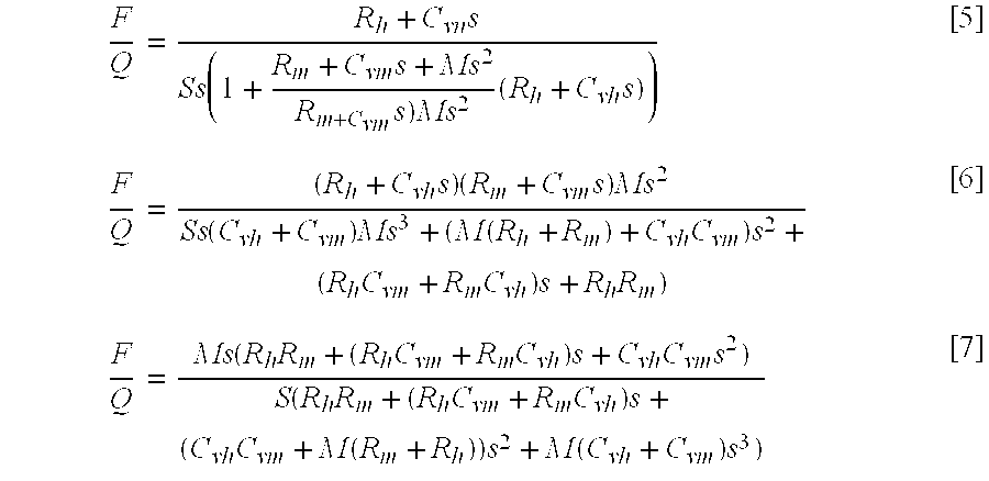
In particular, the Laplace equation relating flow rate, force, and displacement is written as follows: Q S ( 1 + C vh R h s ) = s ( y + C vh R h sy + 1 R h F ) [ 2 ]
Figure US06693399-20040217-M00002
or indeed F = ( R h + C vh s ) ( Q Ss - y ) [ 3 ]
Figure US06693399-20040217-M00003
Combining these three equations gives: y = F · R m + C vm s + Ms 2 ( R m + C vm s ) Ms 2 [ 4 ]
Figure US06693399-20040217-M00004
Equation [2] can then be expressed as a function of [4] as follows: F Q = R h + C vn s Ss ( 1 + R m + C vm s + Ms 2 R m + C vm s ) Ms 2 ( R h + C vh s ) ) [ 5 ] F Q = ( R h + C vh s ) ( R m + C vm s ) Ms 2 Ss ( C vh + C vm ) Ms 3 + ( M ( R h + R m ) + C vh C vm ) s 2 + ( R h C vm + R m C vh ) s + R h R m ) [ 6 ] F Q = Ms ( R h R m + ( R h C vm + R m C vh ) s + C vh C vm s 2 ) S ( R h R m + ( R h C vm + R m C vh ) s + ( C vh C vm + M ( R m + R h ) ) s 2 + M ( C vh + C vm ) s 3 ) [ 7 ]
Figure US06693399-20040217-M00005
The position or force transfer y/Q can thus be resolved as a first transfer function F/Q given by [7] followed by a second equation y/F whose transfer function is given by [4], position servo-control being performed on the complete system at y/Q.
It should be observed that the expression for F/Q has a derivative term in the numerator and a resonance given by the preponderant terms in the denominator of frequency 1 2 π R h R m M ( R h + R m ) .
Figure US06693399-20040217-M00006
This is practically the appearance of F/Q which therefore has the shape shown in FIG. 3a.
The resonance leads to peaks where force is very high, particularly whenever there is a change of control sign.
Position transfer y/F has the appearance shown in FIG. 3b, with a drop of gain at frequency F2 given mainly by 1 2 π R m M
Figure US06693399-20040217-M00007
and prevents no particular control problem. The ratio between the frequencies F1 and F2 is R h R h + R m
Figure US06693399-20040217-M00008
and F1 is always smaller than F2.
A model for use in the force control loop 6 can be deduced from knowledge of the linear transfer function F/Q.
The transfer function PF(s) corresponding to this model can be selected so as to correspond to F/Q at very low frequencies and eliminate as much as possible the resonance around F1.
In particular, by using a transfer function PF(s) of appearance that is the same as that of the theoretical transfer function F/Q except in the immediate vicinity of F1, it is possible to obtain results that are very robust, significantly reducing the force of the servo-control or the actuator at transitions.
An example of the transfer function for this reference model can be as follows: F ref Q ref = ks ( 1 2 π f 0 ) 2 s 2 + 2 x 2 π f 0 s + 1 · B ( s )
Figure US06693399-20040217-M00009
This transfer function is shown in FIG. 3c where it is superposed on the transfer function of FIG. 3a (dashed line) and it is obtained on the basis of a priori knowledge concerning the structure of F/Q, specifically a pure derivative term in the numerator, and a second order of natural angular frequency f0 which is not necessarily exactly equal to F1 (for example, an error of 20% relative to F1 is completely acceptable, with a damping factor χ which, for example, can be of magnitude lying in the range 0.7 to 1 and which serves to eliminate the overload). In the above equation, B(s) represents a filter term which in simplified form can be taken to be equal to 1; k is a gain term which corresponds to the transfer function CF(s).
Naturally, other types of reference model could be used. Nevertheless, those given above present the advantage of being efficient, simple to use, and robust.
It should also be observed that the reference model described above can also advantageously be used when servo-controlling force.
Also, it will be observed that the devices proposed by the invention can advantageously be used in servo-control devices having a plurality of servo-control loops in parallel.
In particular, the invention is easily implemented on conventional servo-control devices in which the various servo-control loops are synchronized by means of force measurements.
It should also be observed that one of the major advantages of the invention lies in that it enables operation of the main servo-control loop (loop 1 in FIG. 1) to continue even if the correction loop for taking force into account (loop 6 in FIG. 1) should fail.

Claims (8)

What is claimed is:
1. A servo-control device comprising:
at least a first servo-control loop which receives a servo-control signal as input and whose output acts on an element to be servo-controlled;
means for determining a parameter measuring the real force generated by the servo-control;
another loop having means for determining an error which is the difference between said parameter measuring the real force and a parameter estimating an acceptable theoretical force which is a function of the servo-control signal; and
means for correcting the processing of the servo-control loop as a function of said error;
wherein the means for determining the error comprise determination means for determining a parameter estimating the acceptable theoretical force on the basis of a reference model, the determination means comprising means for implementing a transfer function having the same appearance as a transfer function or determining the parameter measuring the real force, except in the vicinity of at least one resonant frequency of said force.
2. A device according to claim 1, wherein an actuator controlled by the first servo-control loop is hydraulic and the reference model is a force/signal transfer function for controlling flow rate.
3. A device according to claim 2, wherein the determination means comprise means for implementing a transfer function having the same appearance as a transfer function for determining the parameter measuring the real force, except in the vicinity of at least one resonant frequency of said force, and wherein said transfer function is: F ref Q ref = ks ( 1 2 π f 0 ) 2 s 2 + 2 x 2 π f 0 s + 1 · B ( s )
Figure US06693399-20040217-M00010
where s represents the Laplacian, and where f0 is equal to or close to a resonant frequency, x being an attenuation factor having magnitude of about 0.7 to 1, k being a gain factor, B(s) being a filter function.
4. A device according to claim 3, wherein the function B(s) is equal to 1.
5. A position servo-control device, constituted by a device according to claim 1.
6. A force servo-control device, constituted by a device according to claim 1.
7. A hydraulic servo-control device, constituted by the device according to claim 1.
8. A servo-control device for actuating a flight control or a test actuator, the device being constituted by a device according to claim 1.
US09/884,176 2000-06-19 2001-06-18 Servo-control devices, in particular for an aircraft flight control actuator Expired - Lifetime US6693399B2 (en)

Applications Claiming Priority (2)

Application Number Priority Date Filing Date Title
FR0007795 2000-06-19
FR0007795A FR2810420B1 (en) 2000-06-19 2000-06-19 IMPROVEMENTS IN POSITION SERVO CONTROL DEVICES, IN PARTICULAR FOR AN AIRCRAFT FLIGHT CONTROL ACTUATOR

Publications (2)

Publication Number Publication Date
US20020038841A1 US20020038841A1 (en) 2002-04-04
US6693399B2 true US6693399B2 (en) 2004-02-17

Family

ID=8851405

Family Applications (1)

Application Number Title Priority Date Filing Date
US09/884,176 Expired - Lifetime US6693399B2 (en) 2000-06-19 2001-06-18 Servo-control devices, in particular for an aircraft flight control actuator

Country Status (5)

Country Link
US (1) US6693399B2 (en)
EP (1) EP1168133B1 (en)
DE (1) DE60114717T2 (en)
ES (1) ES2248252T3 (en)
FR (1) FR2810420B1 (en)

Cited By (2)

* Cited by examiner, † Cited by third party
Publication number Priority date Publication date Assignee Title
US20110057071A1 (en) * 2009-09-10 2011-03-10 Vineet Sahasrabudhe Life improving flight control system
US10144501B2 (en) * 2015-07-21 2018-12-04 Airbus Operations S.A.S. Method and device for automatic management of an actuator controlled by a servo-valve

Families Citing this family (2)

* Cited by examiner, † Cited by third party
Publication number Priority date Publication date Assignee Title
ES2359308B1 (en) * 2009-10-13 2012-03-23 Universitat Politécnica de Catalunya SERVOMING FOR VEHICLE CONTROL.
CN102520725B (en) * 2011-12-08 2013-10-16 北京控制工程研究所 Characteristic mass obtaining method based on safety area

Citations (15)

* Cited by examiner, † Cited by third party
Publication number Priority date Publication date Assignee Title
US4079906A (en) * 1976-04-05 1978-03-21 Societe Nationale Industrielle Aerospatiale Servo-control device for controlling a control surface of an aircraft
US4089494A (en) * 1976-12-16 1978-05-16 Mcdonnell Douglas Corporation Reduced servo noise control for a hydraulic actuator
US4195337A (en) * 1977-05-26 1980-03-25 Agence Nationale De Valorisation De La Recherche (Anvar) Control method utilizing a model control scheme
US4492907A (en) * 1982-06-28 1985-01-08 Rockwell International Corporation Combined series and parallel servo control for aircraft
US4527242A (en) * 1982-06-28 1985-07-02 Rockwell International Corporation Automatic flight control pilot assist system
US4849900A (en) * 1986-05-02 1989-07-18 The Boeing Company Flight control system and method
US4992713A (en) * 1988-10-11 1991-02-12 Rockwell International Corporation Aircraft autopilot with yaw control by rudder force
FR2660705A1 (en) 1990-04-10 1991-10-11 Renault Device for servo control of a hydraulic jack in terms of force and motor vehicle suspension equipped with such a device
US5117170A (en) 1985-12-23 1992-05-26 Life Fitness Motor control circuit for a simulated weight stack
US5136227A (en) 1985-09-10 1992-08-04 Agency Of Industrial Science & Technology, Ministry Of International Trade & Industry Active gravity compensation device for force control system
US5233512A (en) * 1990-06-21 1993-08-03 General Electric Company Method and apparatus for actuator fault detection
US5291113A (en) * 1992-10-06 1994-03-01 Honeywell Inc. Servo coupled hand controllers
US5552690A (en) * 1992-08-10 1996-09-03 Sumitomo Heavy Industries, Ltd. Control unit capable of improving a response characteristic and a tracking property by selecting an optimum gain in accordance with an operating condition
US5862894A (en) * 1996-07-05 1999-01-26 Gec Alsthom Transport Sa Semi-active damper with continuous force control
EP0897111A2 (en) 1997-08-13 1999-02-17 Japan Tobacco Inc. Material testing machine

Patent Citations (15)

* Cited by examiner, † Cited by third party
Publication number Priority date Publication date Assignee Title
US4079906A (en) * 1976-04-05 1978-03-21 Societe Nationale Industrielle Aerospatiale Servo-control device for controlling a control surface of an aircraft
US4089494A (en) * 1976-12-16 1978-05-16 Mcdonnell Douglas Corporation Reduced servo noise control for a hydraulic actuator
US4195337A (en) * 1977-05-26 1980-03-25 Agence Nationale De Valorisation De La Recherche (Anvar) Control method utilizing a model control scheme
US4492907A (en) * 1982-06-28 1985-01-08 Rockwell International Corporation Combined series and parallel servo control for aircraft
US4527242A (en) * 1982-06-28 1985-07-02 Rockwell International Corporation Automatic flight control pilot assist system
US5136227A (en) 1985-09-10 1992-08-04 Agency Of Industrial Science & Technology, Ministry Of International Trade & Industry Active gravity compensation device for force control system
US5117170A (en) 1985-12-23 1992-05-26 Life Fitness Motor control circuit for a simulated weight stack
US4849900A (en) * 1986-05-02 1989-07-18 The Boeing Company Flight control system and method
US4992713A (en) * 1988-10-11 1991-02-12 Rockwell International Corporation Aircraft autopilot with yaw control by rudder force
FR2660705A1 (en) 1990-04-10 1991-10-11 Renault Device for servo control of a hydraulic jack in terms of force and motor vehicle suspension equipped with such a device
US5233512A (en) * 1990-06-21 1993-08-03 General Electric Company Method and apparatus for actuator fault detection
US5552690A (en) * 1992-08-10 1996-09-03 Sumitomo Heavy Industries, Ltd. Control unit capable of improving a response characteristic and a tracking property by selecting an optimum gain in accordance with an operating condition
US5291113A (en) * 1992-10-06 1994-03-01 Honeywell Inc. Servo coupled hand controllers
US5862894A (en) * 1996-07-05 1999-01-26 Gec Alsthom Transport Sa Semi-active damper with continuous force control
EP0897111A2 (en) 1997-08-13 1999-02-17 Japan Tobacco Inc. Material testing machine

Cited By (3)

* Cited by examiner, † Cited by third party
Publication number Priority date Publication date Assignee Title
US20110057071A1 (en) * 2009-09-10 2011-03-10 Vineet Sahasrabudhe Life improving flight control system
US9102399B2 (en) 2009-09-10 2015-08-11 Sikorsky Aircraft Corporation Life improving flight control system
US10144501B2 (en) * 2015-07-21 2018-12-04 Airbus Operations S.A.S. Method and device for automatic management of an actuator controlled by a servo-valve

Also Published As

Publication number Publication date
US20020038841A1 (en) 2002-04-04
FR2810420A1 (en) 2001-12-21
FR2810420B1 (en) 2004-10-08
DE60114717T2 (en) 2006-07-20
EP1168133A1 (en) 2002-01-02
DE60114717D1 (en) 2005-12-15
ES2248252T3 (en) 2006-03-16
EP1168133B1 (en) 2005-11-09

Similar Documents

Publication Publication Date Title
KR101223669B1 (en) Engine bench system control system
CN100578412C (en) Machine position control device
KR101062230B1 (en) Dynamic stiffness measuring device and its control method
US5424637A (en) Method and apparatus for determining the position of an armature in an electromagnetic actuator using observer theory
CN110928182B (en) Robust self-adaptive repetitive control method of hydraulic servo system based on state estimation
US7493826B2 (en) Velocity feedback compensation for force control systems
US6252369B1 (en) Motor speed controller and gain setting method of the controller
EP2308755A2 (en) Methods and systems for reducing the structural coupling phenomenon in systems for controlling an air refuelling boom
US6693399B2 (en) Servo-control devices, in particular for an aircraft flight control actuator
CN105388841A (en) Servo control apparatus
KR19980083174A (en) Vibration Suppression Control Method and Control Apparatus of Resonance System
Clarke et al. Adaptive control of materials-testing machines
CN106089857B (en) The test system and test method of the dynamic pressure feedback effect frequency characteristic of servo valve
US6828749B2 (en) Full-closed control apparatus
Khalil et al. Implementation of single feedback control loop for constant power regulated swash plate axial piston pumps
JPH07293038A (en) Damping device
JP3490561B2 (en) Servo control system
EP3997551A1 (en) Force compensation method and device
KR20210019661A (en) Structural coupling test method using variable gain modulator
CN115230805B (en) Accurate steering control method for heavy-load AGV
KR101060990B1 (en) Resonance Suppression Control Method for Position Servo Flight Control System
JP3295102B2 (en) Equivalent disturbance compensation method
CN113954078B (en) Force control joint control method and device, robot and readable storage medium
US7139643B2 (en) Control device with servocontrol loop, particularly an electro-hydraulic flight control actuator
Matulewicz et al. Optimal design of thin-walled I beams undergoing torsion

Legal Events

Date Code Title Description
AS Assignment

Owner name: TRW SYSTEMES AERONAUTIQUES CIVILS, FRANCE

Free format text: ASSIGNMENT OF ASSIGNORS INTEREST;ASSIGNOR:SILVESTRO, GENEVIEVE;REEL/FRAME:012264/0331

Effective date: 20010801

AS Assignment

Owner name: GOODRICH CONTROL SYSTEMS, FRANCE

Free format text: ASSIGNMENT OF ASSIGNORS INTEREST;ASSIGNOR:TRW SYSTEMES AERONAUTIQUES CIVILS;REEL/FRAME:013933/0399

Effective date: 20021001

STCF Information on status: patent grant

Free format text: PATENTED CASE

CC Certificate of correction
FPAY Fee payment

Year of fee payment: 4

FPAY Fee payment

Year of fee payment: 8

FPAY Fee payment

Year of fee payment: 12