US6688282B1 - Power-based idle speed control - Google Patents
Power-based idle speed control Download PDFInfo
- Publication number
- US6688282B1 US6688282B1 US10/064,909 US6490902A US6688282B1 US 6688282 B1 US6688282 B1 US 6688282B1 US 6490902 A US6490902 A US 6490902A US 6688282 B1 US6688282 B1 US 6688282B1
- Authority
- US
- United States
- Prior art keywords
- engine
- actuator
- torque
- idle
- speed
- Prior art date
- Legal status (The legal status is an assumption and is not a legal conclusion. Google has not performed a legal analysis and makes no representation as to the accuracy of the status listed.)
- Expired - Lifetime, expires
Links
Images


Classifications
-
- F—MECHANICAL ENGINEERING; LIGHTING; HEATING; WEAPONS; BLASTING
- F02—COMBUSTION ENGINES; HOT-GAS OR COMBUSTION-PRODUCT ENGINE PLANTS
- F02D—CONTROLLING COMBUSTION ENGINES
- F02D37/00—Non-electrical conjoint control of two or more functions of engines, not otherwise provided for
- F02D37/02—Non-electrical conjoint control of two or more functions of engines, not otherwise provided for one of the functions being ignition
-
- F—MECHANICAL ENGINEERING; LIGHTING; HEATING; WEAPONS; BLASTING
- F02—COMBUSTION ENGINES; HOT-GAS OR COMBUSTION-PRODUCT ENGINE PLANTS
- F02D—CONTROLLING COMBUSTION ENGINES
- F02D31/00—Use of speed-sensing governors to control combustion engines, not otherwise provided for
- F02D31/001—Electric control of rotation speed
- F02D31/002—Electric control of rotation speed controlling air supply
- F02D31/003—Electric control of rotation speed controlling air supply for idle speed control
-
- F—MECHANICAL ENGINEERING; LIGHTING; HEATING; WEAPONS; BLASTING
- F02—COMBUSTION ENGINES; HOT-GAS OR COMBUSTION-PRODUCT ENGINE PLANTS
- F02D—CONTROLLING COMBUSTION ENGINES
- F02D41/00—Electrical control of supply of combustible mixture or its constituents
- F02D41/02—Circuit arrangements for generating control signals
- F02D41/14—Introducing closed-loop corrections
- F02D41/16—Introducing closed-loop corrections for idling
-
- F—MECHANICAL ENGINEERING; LIGHTING; HEATING; WEAPONS; BLASTING
- F02—COMBUSTION ENGINES; HOT-GAS OR COMBUSTION-PRODUCT ENGINE PLANTS
- F02D—CONTROLLING COMBUSTION ENGINES
- F02D41/00—Electrical control of supply of combustible mixture or its constituents
- F02D41/02—Circuit arrangements for generating control signals
- F02D41/14—Introducing closed-loop corrections
- F02D41/1401—Introducing closed-loop corrections characterised by the control or regulation method
- F02D2041/1413—Controller structures or design
- F02D2041/1418—Several control loops, either as alternatives or simultaneous
-
- F—MECHANICAL ENGINEERING; LIGHTING; HEATING; WEAPONS; BLASTING
- F02—COMBUSTION ENGINES; HOT-GAS OR COMBUSTION-PRODUCT ENGINE PLANTS
- F02D—CONTROLLING COMBUSTION ENGINES
- F02D2200/00—Input parameters for engine control
- F02D2200/02—Input parameters for engine control the parameters being related to the engine
- F02D2200/10—Parameters related to the engine output, e.g. engine torque or engine speed
- F02D2200/1006—Engine torque losses, e.g. friction or pumping losses or losses caused by external loads of accessories
-
- F—MECHANICAL ENGINEERING; LIGHTING; HEATING; WEAPONS; BLASTING
- F02—COMBUSTION ENGINES; HOT-GAS OR COMBUSTION-PRODUCT ENGINE PLANTS
- F02D—CONTROLLING COMBUSTION ENGINES
- F02D2250/00—Engine control related to specific problems or objectives
- F02D2250/18—Control of the engine output torque
-
- F—MECHANICAL ENGINEERING; LIGHTING; HEATING; WEAPONS; BLASTING
- F02—COMBUSTION ENGINES; HOT-GAS OR COMBUSTION-PRODUCT ENGINE PLANTS
- F02D—CONTROLLING COMBUSTION ENGINES
- F02D31/00—Use of speed-sensing governors to control combustion engines, not otherwise provided for
- F02D31/001—Electric control of rotation speed
- F02D31/007—Electric control of rotation speed controlling fuel supply
- F02D31/008—Electric control of rotation speed controlling fuel supply for idle speed control
Definitions
- the invention relates to a method and system for regulating engine idle speed of an internal combustion engine equipped with an electronic throttle.
- airflow to the engine is controlled based on demanded engine torque, which is determined from accelerator pedal position.
- This torque-based type of control is suitable for operating conditions for which the operator is demanding a non-negligible torque.
- the desire is to maintain a constant engine speed.
- airflow is feedback, controlled to provide a desired constant engine speed during idle.
- the inventors of the present invention have recognized a problem in combining control based on airflow at idle and torque based control at higher torque conditions. Specifically, the inventors have recognized that engine speed my deviate from the desired value due to a torque bump when traversing between the two engine control modes.
- variable displacement engine is one in which some of the engine cylinders are deactivated at low torque causing the engine to deliver higher fuel economy than using all engine cylinders to deliver the desired torque.
- the problem is in maintaining constant idle speed when a transition in the number of activated cylinders occurs.
- the inventors of the present invention have controlled two actuators, e.g., spark and throttle, controlling both based on a single idle torque. Idle speed control was degraded using this method because the two actuators operating on the same request to alter idle torque interfere with each other thereby failing to provide sufficient engine speed regulation.
- the present invention addresses shortcomings discussed above by providing a method and system for regulating idle speed based on a power requirement.
- a method for regulating idle speed of an engine includes determining a target engine idle speed based on an engine operating condition; determining a power requirement based on the target engine idle speed; determining actual engine speed; controlling a first engine actuator (e.g., a slower actuator) based on the power requirement and the target engine idle speed; and controlling a second engine actuator (e.g., a faster actuator) based on the power requirement and the actual engine speed.
- a first engine actuator e.g., a slower actuator
- a second engine actuator e.g., a faster actuator
- the first engine actuator is a slow engine actuator that may require multiple engine cycles to effect a change in engine speed. Because of its relatively slower ability to respond, it is controlled based on the target speed desired.
- the second engine actuator is a fast engine actuator that is capable of affecting engine by, for example, the next combustion event. Because of its relatively faster ability to respond, the second actuator can respond to situations that make the actual engine speed change. Examples of slow engine actuators include throttle valve actuators and valve timing actuators. Examples of fast engine actuators include ignition actuators and fuel actuators.
- the method may further include adjusting the power requirement based on deviation of the actual engine speed from the target engine idle speed to obtain an adjusted power requirement.
- the method may include determining a desired power reserve, and adjusting the adjusted power requirement based on the desired power reserve to obtain a first adjusted power requirement.
- the step of controlling a first engine actuator may then comprise controlling the first engine actuator based on the first adjusted power requirement and the target engine idle speed.
- the method may be applied to an engine which is a multi-cylinder, variable displacement engine capable of deactivating one or more of said cylinders.
- the method may further include controlling the first actuator, preferably a throttle valve, based on the number of deactivated cylinders and controlling the second actuator, preferably a spark advance timing, also based on the number of deactivated cylinders.
- the method may further include determining a desired power ratio based on the desired power reserve, determining an actual power ratio based on engine operating conditions, and adjusting the adjusted power requirement based on the difference between the desired power ratio and the actual power ratio to obtain a second adjusted power requirement. Controlling a second engine actuator may then be based on the second adjusted power requirement and the actual engine speed.
- a system for regulating engine idle speed of an engine includes an operating condition sensor for sensing an engine operating condition, and an engine speed sensor for sensing actual engine speed.
- the system further includes an electronic control unit in electrical communication with the operating condition sensor and the engine speed sensor, and first and second engine actuators in electrical communication with the electronic control unit.
- the electronic control unit includes instructions for determining a target engine idle speed based on the engine operating condition, instructions for determining a power requirement based on the target engine idle speed, instructions for controlling the first engine actuator based on the power requirement and the target engine idle speed, and instructions for controlling the second engine actuator based on the power requirement and the actual engine speed.
- idle control is based on torques computed for first and second actuators. Since control outside of idle is also based on torque, a transition between idle and non-idle is facilitated by the present invention.
- the inventors of the present invention have recognized an advantage of the present invention is that a smoother transition is possible between the two operating regimes. Specifically, the transition occurs without incurring a speed deviation or discontinuity, which would be undesirable to the operator of the vehicle.
- the present invention also provides smooth transitions among operating modes in a variable displacement engine (VDE) during idle.
- VDE variable displacement engine
- a VDE disables some of the engine's cylinders when demanded engine torque is low to provide increased fuel economy.
- a VDE may also operate with some of the cylinders disabled at idle to obtain fuel savings.
- operation of all cylinders may be requested at idle: during cold weather operation to heat the engine and after-treatment system and to provide smooth operation; during performance of an engine diagnostic operation, such as an emission control system evaluation; during carbon canister vapor purge; and others.
- an engine diagnostic operation such as an emission control system evaluation
- carbon canister vapor purge during carbon canister vapor purge
- the inventors of the present invention have recognized that by regulating engine speed during idle according to the present invention, i.e., based on controlling the first and second actuators on first and second torques, respectively, and further basing the control of the actuators on the number of deactivated cylinders, a transition between partial and full cylinder operation, and vice versa, of the VDE can occur without a speed flare because the idle speed controller is still in control during the transition.
- the inventors have also recognized another advantage of the present invention by basing the torque calculation for controlling the first actuator on the desired or target idle speed and basing the torque calculation for controlling the second actuator on the actual idle speed that idle speed regulation is more robust than if both actuators were controlled based on the same torque.
- FIG. 1 is a schematic diagram of a system according to the invention for regulating engine idle speed of an engine
- FIG. 2 is a flowchart illustrating operation of a method according to the invention for regulating engine idle speed
- FIG. 3 is a flowchart illustrating operation of a method according to the invention for regulating engine idle speed
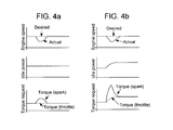
- FIGS. 4 a and 4 b are graphs illustrating operational aspects of a system according to the invention.
- FIGS. 5 a and 5 b are graphs illustrating operational aspects of prior art systems.
- FIG. 1 shows an internal combustion engine 10 with an intake system 12 in which a throttle valve 32 is disposed.
- engine 10 has four cylinders 16 in which spark plugs 11 are disposed. Cylinders 16 are supplied fuel by injectors 26 .
- Engine 10 is equipped with an exhaust gas recirculation system (EGR) 19 which connects the exhaust 14 system with the intake system 12 via an EGR valve 18 .
- EGR exhaust gas recirculation system
- the engine is coupled to a toothed disk 20 .
- a sensor 22 detects the teeth of disk 20 , whereby engine speed can be computed in the engine controller.
- ECU 40 is provided to control engine 10 .
- ECU 40 has a microprocessor 46 , called a central processing unit (CPU), in communication with memory management unit (MMU) 48 .
- MMU 48 controls the movement of data among the various computer readable storage media and communicates data to and from CPU 46 .
- the computer readable storage media preferably include volatile and nonvolatile storage in read-only memory (ROM) 50 , random-access memory (RAM) 54 , and keep-alive memory (KAM) 52 , for example.
- KAM 52 may be used to store various operating variables while CPU 46 is powered down.
- the computer-readable storage media may be implemented using any of a number of known memory devices such as PROMs (programmable read-only memory), EPROMs (electrically PROM), EEPROMs (electrically erasable PROM), flash memory, or any other electric, magnetic, optical, or combination memory devices capable of storing data, some of which represent executable instructions, used by CPU 46 in controlling the engine or vehicle into which the engine is mounted.
- the computer-readable storage media may also include floppy disks, CD-ROMs, hard disks, and the like.
- CPU 46 communicates with various sensors and actuators via an input/output (I/O) interface 44 .
- Examples of items that are actuated under control by CPU 46 , through I/O interface 44 are fuel injection timing, fuel injection rate, fuel injection duration, throttle valve 32 position, spark plug 11 timing, EGR valve 18 position.
- Various other sensors 42 and specific sensors (engine speed sensor 22 , pedal position sensor 30 , manifold absolute pressure sensor 31 , exhaust gas component sensor 24 , air temperature sensor 34 , and mass airflow sensor 36 , engine coolant sensor 38 ) communicate input through I/O interface 44 and indicate such things as engine rotational speed, vehicle speed, coolant temperature, manifold pressure, pedal position, throttle valve position, air temperature, exhaust stoichiometry, exhaust component concentration, and air flow.
- Some ECU 40 architectures do not contain MMU 48 .
- CPU 46 manages data and connects directly to ROM 50 , RAM 54 , and KAM 52 .
- the present invention could utilize more than one CPU 46 to provide engine control and ECU 60 may contain multiple ROM 50 , RAM 54 , and KAM 52 coupled to MMU 48 or CPU 46 depending upon the particular application.
- FIG. 2 illustrates a simplified version of an embodiment of the present invention.
- the routine starts in step 60 . From step 60 , both steps 62 (determining the target idle speed) and 64 (determining the actual idle speed) are accomplished, in any order. Based on the target idle speed, the idle power requirement can be determined, step 66 . Based on the well known relationship,
- a first torque is computed based on the idle power requirement, as determined in step 66 , and the target idle speed, as determined in step 62 :
- Torque 1 Power/(2* ⁇ *Speed target ).
- a second torque is determined, in step 70 , based on idle power requirement (from step 66 ) and the actual idle speed, as determined in step 64 :
- Torque 2 Power/(2* ⁇ *Speed actual ).
- the first torque is used to control a slow actuator, step 72 ; and the second torque is used to control a fast actuator, step 74 .
- the routine of FIG. 2 continues during idle and an alternative control scheme, which is not a part of the present invention, is accessed when the driver demand is for positive output torque.
- the first engine actuator is a slow engine actuator that requires multiple engine cycles, e.g., three to ten engine revolutions, to change engine speed.
- Examples of slow engine actuators include throttle valve 32 and valve actuators (not shown), such as variable cam timing actuators and variable valve lift actuators which are hydraulically actuated.
- Throttle valve 32 has a large range of authority allowing it to address sustained increases in demanded torque.
- the second engine actuator is a fast actuator, which can cause a change in torque produced by the engine, and thus engine speed, within one revolution of the engine.
- the second actuator is, typically, the electronic ignition system, which affects spark timing.
- the second actuator is a fuel injection system, in which fuel pulse width commanded to the next injector to inject is increased.
- the fast actuator is a valve actuator, which is capable of adjustment within one engine revolution, such as a solenoid actuated valve system. This fast actuator has a wide range of authority in controlling torque.
- step 66 in which the idle power requirement is determined can be considered a feed-forward controller in which engine losses are estimated.
- Engine losses include friction, pumping, and accessory. Frictional losses comprise: piston ring-bore friction, bearing friction, valve train friction, as examples.
- Pumping losses is the work performed by the engine in pumping fresh charge past the throttle and expelling burned gases through the exhaust system. Accessory losses are due to the oil pump, water pump, air conditioner, power steering pump, alternator, as examples. These losses are estimated based on oil temperature, engine speed, manifold pressure, and other engine parameters known within ECU 40 .
- the load placed on the engine by accessories, such as the alternator and air conditioner varies as the demand for charging and cooling, respectively, vary. In spite of the variation in the losses, which may change in a stepwise manner, idle speed control is maintained. If the losses are computed in terms of torque, they are converted to power, through the equation above.
- the determination of idle power requirement, step 66 can be further broken down into two steps, the first being the estimation of engine losses as described above.
- the idle power requirement is corrected based on a deviation of the actual engine speed from the target engine idle speed.
- the losses incurred by the engine may change stepwise.
- An example of this is when an air conditioning compressor is activated.
- the engine torque required to maintain engine speed increases stepwise.
- the spark timing is retarded from its optimal timing.
- spark, a fast actuator is immediately adjusted toward its optimal timing. In this way, the sudden demand for an increase in torque is satisfied.
- a slow actuator e.g., the throttle valve
- spark is simultaneously adjusted to its prior retarded condition so that if a further increase in torque were to be demanded, the capability to do so would be available with a rapid spark timing adjustment.
- the power reserve is provided by operating the second (fast) actuator at a condition, which provides less than the power that would be developed at its optimal setting. The effectiveness in providing additional power rapidly is ensured by providing the diminution in power by the faster actuator setting because the faster actuator can react rapidly to a call for higher power.
- the above-described desire to operate engine 10 at a condition in which there is reserve power is an embodiment of the present invention.
- the desired power reserve is a value determined in ECU 40 . It may be a constant value or based on a lookup table as a function of operating condition. A typical value of desired power reserve is 5%, although it could also be a range.
- Steps 60 , 62 , 64 , and 66 are identical to FIG. 2 and described in regards to FIG. 2 .
- steps 80 and 82 the actual and desired power reserves are determined.
- the actual power reserve is computed from:
- step 84 the error between actual ( 80 ) and desired ( 82 ) power reserves is determined.
- step 90 a first torque is determined based on the target idle speed (step 62 ), the idle power requirement (step 66 ), and the error in power reserve (step 84 ).
- step 96 the slow actuator is controlled based on first torque from step 90 .
- the slow actuator provides a sustained increase in torque.
- the slow actuator is the actuator that attains a position which brings the error in power reserve to zero.
- the second torque computed in step 92 which is used to control the fast actuator in step 98 , is based on scaled idle power requirement in step 88 , which is based on the desired power reserve.
- engine 10 is a VDE engine
- the control of the first and second actuators are further based on information about the VDE mode. Specifically, information about the number of deactivated cylinders is used by the controllers to provide a smooth transition among VDE modes at idle, step 94 of FIG. 3 .
- FIGS. 4 a and 4 b show operational aspects of a system that includes a throttle valve as a first engine actuator and an ignition system (spark timing) as the second actuator.
- the idle power is constant for the time period shown in the graph.
- an engine speed drop occurs, which could possibly be due to a poor combustion event or a transition in a VDE.
- the desired engine speed is constant throughout the time period in FIG. 4 a .
- the first torque that for controlling the throttle
- the second torque that for controlling the spark in the present example, increases in reaction to the actual speed dropping.
- spark is used to cause actual engine speed to quickly return to desired engine speed. Once actual engine speed returns to desired idle speed, second torque returns to the prior value.
- FIG. 4 b a case is shown in which the idle power requirement increases over time. This could be in response to a change in alternator load or an air conditioner compressor turning on or other demand for additional power from the engine.
- a dip in actual engine speed occurs.
- the second torque which is commanded to spark
- the increase in second torque is more pronounced than in FIG. 4 a because the idle power requirement has simultaneously increased due to the change in accessory power requirement.
- first torque that commanded to the throttle valve
- first torque does increase in response to the increase in idle power requirement.
- FIG. 4 b demonstrates how the faster actuator, spark in the present example, reacts to rapid demands for increased torque; whereas, the slower actuator, throttle valve in the present example reacts to a sustained increase in idle power requirement and stays at the higher level.
- FIGS. 5 a and 5 b illustrate the problems of prior art methods in more detail. Both FIGS. 5 a and 5 b relate to the situation of FIG. 4 b , in which a drop in engine speed occurs due to a change in accessory power requirement.
- FIG. 5 a indicates the result if only a slow actuator, preferably the throttle valve, is actuated to maintain idle speed. The difference in the actual and desired idle speeds is used to communicate a torque request to the slow actuator. Because it is a slow actuator, the actual torque lags that requested torque. Due to the lag, the engine idle speed drops farther than the other examples which also use a faster actuator. Also, because of the lag, the idle speed overshoots.
- FIG. 5 b indicates the situation in which both slow and fast actuators are employed and both actuators are supplied the same control signal. Because a faster actuator, preferably spark, is used, the engine speed does not drop so low before the system reacts and causes idle speed to rise. However, because both actuators are trying to achieve the same goal of increasing spark and the torque response of the two actuators is at a different rate, the actual torque oscillates at a greater amplitude than requested torque and oscillates for a longer period of time. Referring once again to FIG. 4 b , an advantage of the present invention is that the two actuators are coordinated, thereby providing a quick recovery from a drop in engine speed with reduced subsequent oscillations.
- a faster actuator preferably spark
Abstract
Description
Claims (27)
Priority Applications (3)
| Application Number | Priority Date | Filing Date | Title |
|---|---|---|---|
| US10/064,909 US6688282B1 (en) | 2002-08-28 | 2002-08-28 | Power-based idle speed control |
| DE10332231A DE10332231B4 (en) | 2002-08-28 | 2003-07-16 | Device method, and computer readable storage medium for power-based idle speed control |
| GB0319156A GB2394320B (en) | 2002-08-28 | 2003-08-15 | A power-based idle speed control |
Applications Claiming Priority (1)
| Application Number | Priority Date | Filing Date | Title |
|---|---|---|---|
| US10/064,909 US6688282B1 (en) | 2002-08-28 | 2002-08-28 | Power-based idle speed control |
Publications (1)
| Publication Number | Publication Date |
|---|---|
| US6688282B1 true US6688282B1 (en) | 2004-02-10 |
Family
ID=28452220
Family Applications (1)
| Application Number | Title | Priority Date | Filing Date |
|---|---|---|---|
| US10/064,909 Expired - Lifetime US6688282B1 (en) | 2002-08-28 | 2002-08-28 | Power-based idle speed control |
Country Status (3)
| Country | Link |
|---|---|
| US (1) | US6688282B1 (en) |
| DE (1) | DE10332231B4 (en) |
| GB (1) | GB2394320B (en) |
Cited By (17)
| Publication number | Priority date | Publication date | Assignee | Title |
|---|---|---|---|---|
| US20030168041A1 (en) * | 2002-03-05 | 2003-09-11 | Nissan Motor Co., Ltd. | Start-up control device for engine |
| US20040069272A1 (en) * | 2002-10-10 | 2004-04-15 | Allen Jeffrey James | Displacement on demand torque smoothing using engine speed control |
| US20040106498A1 (en) * | 2002-11-30 | 2004-06-03 | Edward Badillo | Method for managing engine torque during a gear shift in an automatic shift manual transmission |
| US6808471B1 (en) * | 2003-05-08 | 2004-10-26 | General Motors Corporation | Methods and apparatus for providing security for electronically-controlled cylinder activation and deactivation |
| US7275518B1 (en) | 2006-04-28 | 2007-10-02 | Ford Global Technologies, Llc | Torque-based powertrain control for vehicles |
| US20090043482A1 (en) * | 2007-08-06 | 2009-02-12 | Ralf Speetzen | Method for controlling an internal combustion engine |
| EP1691061A3 (en) * | 2005-02-15 | 2009-05-13 | Toyota Jidosha Kabushiki Kaisha | Control device of internal combustion engine |
| US20100033314A1 (en) * | 2008-08-05 | 2010-02-11 | Toyota Motor Engineering & Manufacturing North America, Inc. | Fuel Enrichment Indicator |
| US20100116250A1 (en) * | 2008-11-07 | 2010-05-13 | Gm Global Technology Operations, Inc. | Method and apparatus for arbitrating torque reserves and loads in torque-based system |
| FR2944831A1 (en) * | 2009-04-22 | 2010-10-29 | Peugeot Citroen Automobiles Sa | Method for adjusting torque reserve at idling speed of spark ignition type internal combustion engine in vehicle, involves temporarily increasing air reserve if ignition advance output of engine reaches predetermined threshold value |
| US20110066357A1 (en) * | 2009-09-17 | 2011-03-17 | Ford Global Technologies, Llc | Inferred oil responsiveness using pressure sensor pulses |
| US20120323462A1 (en) * | 2009-12-18 | 2012-12-20 | Markus Henzler | Method for operating a drive unit, and control device for a drive unit |
| US20140172273A1 (en) * | 2012-12-13 | 2014-06-19 | GM Global Technology Operations LLC | System and method for controlling torque output of an engine when a water pump coupled to the engine is switched on or off |
| US20150291004A1 (en) * | 2014-04-11 | 2015-10-15 | Toyota Jidosha Kabushiki Kaisha | Engine rotational speed control apparatus |
| US20160222899A1 (en) * | 2015-02-04 | 2016-08-04 | Ford Global Technologies, Llc | Method and system for exhaust catalyst warming |
| WO2018182494A1 (en) * | 2017-03-31 | 2018-10-04 | Scania Cv Ab | Control of an automated clutch and of an engine torque |
| US11352964B2 (en) * | 2017-10-06 | 2022-06-07 | Briggs & Stratton, Llc | Cylinder deactivation for a multiple cylinder engine |
Families Citing this family (9)
| Publication number | Priority date | Publication date | Assignee | Title |
|---|---|---|---|---|
| EP1826380B1 (en) * | 2006-02-24 | 2010-08-04 | Ford Global Technologies, LLC | A method for controlling the idle speed of an internal combustion engine, and an internal combustion engine |
| US7463970B2 (en) * | 2006-11-28 | 2008-12-09 | Gm Global Technology Operations, Inc. | Torque based engine speed control |
| US7418943B2 (en) * | 2006-11-30 | 2008-09-02 | Gm Global Technology Operations, Inc. | Spark advance foe engine idle speed control |
| JP2008215320A (en) * | 2007-03-07 | 2008-09-18 | Denso Corp | Torque control system |
| US7606652B2 (en) * | 2007-11-02 | 2009-10-20 | Gm Global Technology Operations, Inc. | Torque based crank control |
| US8116954B2 (en) * | 2007-11-02 | 2012-02-14 | GM Global Technology Operations LLC | RPM to torque transition control |
| US8631783B2 (en) * | 2009-11-18 | 2014-01-21 | GM Global Technology Operations LLC | Method and apparatus for controlling engine torque during intrusive testing |
| DE102014001581B4 (en) * | 2014-02-06 | 2017-04-06 | Mtu Friedrichshafen Gmbh | Method of execution with an internal combustion engine arranged for a cylinder deactivation operation |
| DE102014009087A1 (en) * | 2014-06-18 | 2015-12-24 | Mtu Friedrichshafen Gmbh | Method for operating an internal combustion engine, engine speed and engine torque stabilization device and internal combustion engine |
Citations (10)
| Publication number | Priority date | Publication date | Assignee | Title |
|---|---|---|---|---|
| US5375574A (en) | 1993-08-18 | 1994-12-27 | Unisia Jecs Corporation | Engine idling speed control apparatus |
| US5463993A (en) | 1994-02-28 | 1995-11-07 | General Motors Corporation | Engine speed control |
| US5479898A (en) * | 1994-07-05 | 1996-01-02 | Ford Motor Company | Method and apparatus for controlling engine torque |
| US5495835A (en) | 1992-04-24 | 1996-03-05 | Mitsubishi Jidosha Kogyo Kabushiki Kaisha | Idling speed control method and apparatus for an internal combustion engine |
| US5662084A (en) | 1995-07-18 | 1997-09-02 | Nissan Motor Co., Ltd. | Engine idling speed control apparatus |
| US5692471A (en) * | 1994-03-07 | 1997-12-02 | Robert Bosch Gmbh | Method and arrangement for controlling a vehicle |
| US5697337A (en) | 1995-11-30 | 1997-12-16 | Nissan Motor Co., Ltd. | Engine rotation speed controller |
| US6098592A (en) * | 1995-10-07 | 2000-08-08 | Robert Bosch Gmbh | Process and device for controlling an internal combustion engine |
| US6109236A (en) | 1997-05-26 | 2000-08-29 | Nissan Motor Co., Ltd. | Engine idle speed controller |
| US6119654A (en) | 1998-02-20 | 2000-09-19 | Daimlerchrysler Ag | Method for adjusting the operating energy input of a motor |
Family Cites Families (2)
| Publication number | Priority date | Publication date | Assignee | Title |
|---|---|---|---|---|
| JP2860852B2 (en) * | 1993-03-18 | 1999-02-24 | 株式会社ユニシアジェックス | Idle speed control device for internal combustion engine |
| JP2002276447A (en) * | 2001-03-19 | 2002-09-25 | Denso Corp | Control device for internal combustion engine |
-
2002
- 2002-08-28 US US10/064,909 patent/US6688282B1/en not_active Expired - Lifetime
-
2003
- 2003-07-16 DE DE10332231A patent/DE10332231B4/en not_active Expired - Lifetime
- 2003-08-15 GB GB0319156A patent/GB2394320B/en not_active Expired - Fee Related
Patent Citations (10)
| Publication number | Priority date | Publication date | Assignee | Title |
|---|---|---|---|---|
| US5495835A (en) | 1992-04-24 | 1996-03-05 | Mitsubishi Jidosha Kogyo Kabushiki Kaisha | Idling speed control method and apparatus for an internal combustion engine |
| US5375574A (en) | 1993-08-18 | 1994-12-27 | Unisia Jecs Corporation | Engine idling speed control apparatus |
| US5463993A (en) | 1994-02-28 | 1995-11-07 | General Motors Corporation | Engine speed control |
| US5692471A (en) * | 1994-03-07 | 1997-12-02 | Robert Bosch Gmbh | Method and arrangement for controlling a vehicle |
| US5479898A (en) * | 1994-07-05 | 1996-01-02 | Ford Motor Company | Method and apparatus for controlling engine torque |
| US5662084A (en) | 1995-07-18 | 1997-09-02 | Nissan Motor Co., Ltd. | Engine idling speed control apparatus |
| US6098592A (en) * | 1995-10-07 | 2000-08-08 | Robert Bosch Gmbh | Process and device for controlling an internal combustion engine |
| US5697337A (en) | 1995-11-30 | 1997-12-16 | Nissan Motor Co., Ltd. | Engine rotation speed controller |
| US6109236A (en) | 1997-05-26 | 2000-08-29 | Nissan Motor Co., Ltd. | Engine idle speed controller |
| US6119654A (en) | 1998-02-20 | 2000-09-19 | Daimlerchrysler Ag | Method for adjusting the operating energy input of a motor |
Cited By (31)
| Publication number | Priority date | Publication date | Assignee | Title |
|---|---|---|---|---|
| US6845749B2 (en) * | 2002-03-05 | 2005-01-25 | Nissan Motor Co., Ltd. | Start-up control device for engine |
| US20030168041A1 (en) * | 2002-03-05 | 2003-09-11 | Nissan Motor Co., Ltd. | Start-up control device for engine |
| US20040069272A1 (en) * | 2002-10-10 | 2004-04-15 | Allen Jeffrey James | Displacement on demand torque smoothing using engine speed control |
| US20040106498A1 (en) * | 2002-11-30 | 2004-06-03 | Edward Badillo | Method for managing engine torque during a gear shift in an automatic shift manual transmission |
| US7300381B2 (en) * | 2002-11-30 | 2007-11-27 | Ford Global Technologies, Llc | Method for managing engine torque during a gear shift in an automatic shift manual transmission |
| US6808471B1 (en) * | 2003-05-08 | 2004-10-26 | General Motors Corporation | Methods and apparatus for providing security for electronically-controlled cylinder activation and deactivation |
| US20040224819A1 (en) * | 2003-05-08 | 2004-11-11 | Bauerle Paul A. | Methods and apparatus for providing security for electronically-controlled cylinder activation and deactivation |
| EP1691061A3 (en) * | 2005-02-15 | 2009-05-13 | Toyota Jidosha Kabushiki Kaisha | Control device of internal combustion engine |
| US7275518B1 (en) | 2006-04-28 | 2007-10-02 | Ford Global Technologies, Llc | Torque-based powertrain control for vehicles |
| US20090043482A1 (en) * | 2007-08-06 | 2009-02-12 | Ralf Speetzen | Method for controlling an internal combustion engine |
| US7788018B2 (en) * | 2007-08-06 | 2010-08-31 | Mtu Friedrichshafen Gmbh | Method for controlling an internal combustion engine |
| CN101363377B (en) * | 2007-08-06 | 2012-12-12 | Mtu腓特烈港有限责任公司 | Method for controlling an internal combustion engine |
| US20100033314A1 (en) * | 2008-08-05 | 2010-02-11 | Toyota Motor Engineering & Manufacturing North America, Inc. | Fuel Enrichment Indicator |
| US7969291B2 (en) * | 2008-08-05 | 2011-06-28 | Toyota Motor Engineering & Manufacturing North America, Inc. | Fuel enrichment indicator |
| US20100116250A1 (en) * | 2008-11-07 | 2010-05-13 | Gm Global Technology Operations, Inc. | Method and apparatus for arbitrating torque reserves and loads in torque-based system |
| US8560204B2 (en) * | 2008-11-07 | 2013-10-15 | GM Global Technology Operations LLC | Method and apparatus for arbitrating torque reserves and loads in torque-based system |
| DE102009051874B4 (en) | 2008-11-07 | 2018-10-25 | GM Global Technology Operations LLC (n. d. Ges. d. Staates Delaware) | Engine control system and method |
| FR2944831A1 (en) * | 2009-04-22 | 2010-10-29 | Peugeot Citroen Automobiles Sa | Method for adjusting torque reserve at idling speed of spark ignition type internal combustion engine in vehicle, involves temporarily increasing air reserve if ignition advance output of engine reaches predetermined threshold value |
| US20110066357A1 (en) * | 2009-09-17 | 2011-03-17 | Ford Global Technologies, Llc | Inferred oil responsiveness using pressure sensor pulses |
| US8079335B2 (en) | 2009-09-17 | 2011-12-20 | Ford Global Technologies, Llc | Inferred oil responsiveness using pressure sensor pulses |
| US20120323462A1 (en) * | 2009-12-18 | 2012-12-20 | Markus Henzler | Method for operating a drive unit, and control device for a drive unit |
| US20140172273A1 (en) * | 2012-12-13 | 2014-06-19 | GM Global Technology Operations LLC | System and method for controlling torque output of an engine when a water pump coupled to the engine is switched on or off |
| US9086026B2 (en) * | 2012-12-13 | 2015-07-21 | GM Global Technology Operations LLC | System and method for controlling torque output of an engine when a water pump coupled to the engine is switched on or off |
| US20150291004A1 (en) * | 2014-04-11 | 2015-10-15 | Toyota Jidosha Kabushiki Kaisha | Engine rotational speed control apparatus |
| EP2930339A3 (en) * | 2014-04-11 | 2015-10-28 | Toyota Jidosha Kabushiki Kaisha | Engine rotational speed control apparatus |
| US10480504B2 (en) * | 2014-04-11 | 2019-11-19 | Toyota Jidosha Kabushiki Kaisha | Engine rotational speed control apparatus |
| US20160222899A1 (en) * | 2015-02-04 | 2016-08-04 | Ford Global Technologies, Llc | Method and system for exhaust catalyst warming |
| US9708993B2 (en) * | 2015-02-04 | 2017-07-18 | Ford Global Technologies, Llc | Method and system for exhaust catalyst warming |
| US9784199B2 (en) * | 2015-02-04 | 2017-10-10 | Ford Global Technologies, Llc | Method and system for exhaust catalyst warming |
| WO2018182494A1 (en) * | 2017-03-31 | 2018-10-04 | Scania Cv Ab | Control of an automated clutch and of an engine torque |
| US11352964B2 (en) * | 2017-10-06 | 2022-06-07 | Briggs & Stratton, Llc | Cylinder deactivation for a multiple cylinder engine |
Also Published As
| Publication number | Publication date |
|---|---|
| DE10332231A1 (en) | 2004-03-25 |
| GB0319156D0 (en) | 2003-09-17 |
| GB2394320A (en) | 2004-04-21 |
| DE10332231B4 (en) | 2010-03-25 |
| GB2394320B (en) | 2005-12-21 |
Similar Documents
| Publication | Publication Date | Title |
|---|---|---|
| US6688282B1 (en) | Power-based idle speed control | |
| JP3403728B2 (en) | Air-fuel ratio control method | |
| US6119063A (en) | System and method for smooth transitions between engine mode controllers | |
| US7082936B2 (en) | Internal combustion engine control device | |
| US6945225B2 (en) | Speed control method | |
| US6182636B1 (en) | Lean burn engine speed control | |
| US20060000441A1 (en) | Speed control method | |
| US20020132701A1 (en) | Apparatus and method for controlling internal combustion engine | |
| US8335631B2 (en) | Method for accommodating extraneous loads during idle operation | |
| US9341125B2 (en) | Engine control apparatus and engine control method | |
| US6470869B1 (en) | Direct injection variable valve timing engine control system and method | |
| JP2002322934A (en) | Intake air control device for internal combustion engine | |
| US7806105B2 (en) | Idle speed control apparatus for internal combustion engine | |
| US7168410B2 (en) | Idle speed controller for internal combustion engine | |
| US6240895B1 (en) | Method for operating an internal combustion engine mainly intended for a motor vehicle | |
| SE522050C2 (en) | Control device for an internal combustion engine | |
| US7690341B2 (en) | Engine intake valve timing control apparatus | |
| US7447586B2 (en) | Valve characteristic control apparatus for internal combustion engine | |
| US6446596B1 (en) | Method of operating an internal combustion engine | |
| US6539914B1 (en) | Internal combustion engine, a control element for the internal combustion engine, and method for operating the internal combustion engine | |
| US8161941B2 (en) | Control device for internal combustion engine | |
| JP2002519559A (en) | Operating method of internal combustion engine | |
| US6173696B1 (en) | Virtual power steering switch | |
| JP3598724B2 (en) | Control device for internal combustion engine | |
| US6792913B1 (en) | Method for operating an internal combustion engine mainly intended for a motor vehicle |
Legal Events
| Date | Code | Title | Description |
|---|---|---|---|
| AS | Assignment |
Owner name: FORD GLOBAL TECHNOLOGIES, INC., MICHIGAN Free format text: ASSIGNMENT OF ASSIGNORS INTEREST;ASSIGNOR:FORD MOTOR COMPANY;REEL/FRAME:013031/0302 Effective date: 20020828 Owner name: FORD MOTOR COMPANY, MICHIGAN Free format text: ASSIGNMENT OF ASSIGNORS INTEREST;ASSIGNORS:OKUBO, CAROL LOUISE;BIDNER, DAVID KARL;DOERING, JEFFREY ALLEN;AND OTHERS;REEL/FRAME:013031/0296;SIGNING DATES FROM 20020801 TO 20020806 |
|
| AS | Assignment |
Owner name: FORD GLOBAL TECHNOLOGIES, LLC, MICHIGAN Free format text: MERGER;ASSIGNOR:FORD GLOBAL TECHNOLOGIES, INC.;REEL/FRAME:013987/0838 Effective date: 20030301 Owner name: FORD GLOBAL TECHNOLOGIES, LLC,MICHIGAN Free format text: MERGER;ASSIGNOR:FORD GLOBAL TECHNOLOGIES, INC.;REEL/FRAME:013987/0838 Effective date: 20030301 |
|
| STCF | Information on status: patent grant |
Free format text: PATENTED CASE |
|
| FPAY | Fee payment |
Year of fee payment: 4 |
|
| FPAY | Fee payment |
Year of fee payment: 8 |
|
| FPAY | Fee payment |
Year of fee payment: 12 |