US6684395B2 - Multiple image dynamic bind and load procedure for a multi-processor - Google Patents

Multiple image dynamic bind and load procedure for a multi-processor Download PDF

Info

Publication number
US6684395B2
US6684395B2 US09/753,084 US75308400A US6684395B2 US 6684395 B2 US6684395 B2 US 6684395B2 US 75308400 A US75308400 A US 75308400A US 6684395 B2 US6684395 B2 US 6684395B2
Authority
US
United States
Prior art keywords
image
processor
processors
instruction memory
revised
Prior art date
Legal status (The legal status is an assumption and is not a legal conclusion. Google has not performed a legal analysis and makes no representation as to the accuracy of the status listed.)
Expired - Fee Related, expires
Application number
US09/753,084
Other versions
US20030046358A1 (en
Inventor
Desmond R. Johnson
Donald F. Hooper
James D. Guilford
Current Assignee (The listed assignees may be inaccurate. Google has not performed a legal analysis and makes no representation or warranty as to the accuracy of the list.)
Intel Corp
Original Assignee
Intel Corp
Priority date (The priority date is an assumption and is not a legal conclusion. Google has not performed a legal analysis and makes no representation as to the accuracy of the date listed.)
Filing date
Publication date
Application filed by Intel Corp filed Critical Intel Corp
Priority to US09/753,084 priority Critical patent/US6684395B2/en
Assigned to INTEL CORPORATION reassignment INTEL CORPORATION ASSIGNMENT OF ASSIGNORS INTEREST (SEE DOCUMENT FOR DETAILS). Assignors: GUILFORD, JAMES D., HOOPER, DONALD F., JOHNSON, DESMOND R.
Publication of US20030046358A1 publication Critical patent/US20030046358A1/en
Application granted granted Critical
Publication of US6684395B2 publication Critical patent/US6684395B2/en
Adjusted expiration legal-status Critical
Expired - Fee Related legal-status Critical Current

Links

Images

Classifications

    • GPHYSICS
    • G06COMPUTING; CALCULATING OR COUNTING
    • G06FELECTRIC DIGITAL DATA PROCESSING
    • G06F9/00Arrangements for program control, e.g. control units
    • G06F9/06Arrangements for program control, e.g. control units using stored programs, i.e. using an internal store of processing equipment to receive or retain programs
    • G06F9/44Arrangements for executing specific programs
    • G06F9/445Program loading or initiating
    • G06F9/44521Dynamic linking or loading; Link editing at or after load time, e.g. Java class loading

Definitions

  • This invention relates generally to multi-processing systems.
  • microcode for the processors is developed on a development station and downloaded from the development station to each of the processors separately. Additionally, in some prior processor architectures, a processor having microcode in internal memory is capable of modifying its own instruction stream as it executes.
  • FIG. 1 is a block diagram of a system employing a multi-processor having a general-purpose processor and a plurality of microengines.
  • FIG. 2 is a block diagram of software executed by the multiprocessor.
  • FIG. 3 is a block diagram of the microengine employed in the multi-processor of FIG. 1 .
  • FIG. 4 is a block diagram of a code development system environment.
  • FIG. 5 is a depiction of a process of generating a microcode object.
  • FIG. 6 is an illustration of an import variable being split between two different microcode instructions.
  • FIG. 7 is a flow diagram of a process of loading the microcode images (generated by the process of FIG. 5) into the microengines.
  • FIG. 8 is an illustration of a process of loading a page of a microcode image into the microengines (shown in FIG. 1 ).
  • FIG. 9 is an alternative process of loading microcode images into the microengines.
  • a system 10 includes a processor 12 that is configured as a multi-processor 12 . That is, the processor 12 includes a plurality of processors 14 a through 14 g .
  • the processor 14 a is a general-purpose processor and processors 14 b - 14 g are microcoded processors (hereinafter, microengines 14 b - 16 g ), each with multiple hardware controlled threads that can be simultaneously active and independently work on a task.
  • microengines 14 b - 16 g microcoded processors
  • Each of the six microengines 14 b - 16 g is capable of processing multiple execution threads.
  • the processor 14 a performs general-purpose computer type functions such as handling protocols, exceptions, extra support for microengine processing when a more detailed processing is needed.
  • the processor 14 a is a StrongARM (ARM is a trademark of ARM Limited, United Kingdom) core based architecture.
  • the processor 14 a (hereinafter, “the core processor” 14 a ) includes an internal CPU 16 coupled to an internal core memory 17 that includes an instruction memory (shown as an instruction cache) 18 , a data memory (shown as a data cache) 20 and read/write buffers 22 .
  • the multi-processor 12 is coupled to a first peripheral bus (shown as a PCI bus) 24 , a second peripheral bus referred to as an I/O bus 26 and a memory system 28 .
  • the processors 14 a - 14 g operate with shared resources including the memory system 28 , a PCI bus interface 30 and an I/O bus interface 32 .
  • the PCI bus interface 30 provides an interface to the PCI bus 24 .
  • the I/O bus interface 32 is responsible for controlling and interfacing the processor 12 to the I/O bus 26 .
  • the memory system 28 includes a Synchronous Dynamic Random Access Memory (SDRAM) 28 a , which is accessed via an SDRAM controller 34 a , a Static Random Access Memory (SRAM) 28 b , which is accessed using an SRAM controller 34 b , and a nonvolatile memory (shown as a FlashROM) 28 c that is used for boot operations and also accessed using the SRAM controller 34 b .
  • SDRAM Synchronous Dynamic Random Access Memory
  • SRAM Static Random Access Memory
  • FlashROM nonvolatile memory
  • the SRAM 28 b and SRAM controller 34 b are used in a for low latency, fast access tasks, e.g., accessing look-up tables, memory for the processor 14 a , and so forth.
  • the processors 14 can execute memory reference instructions to either the SDRAM controller 34 a or the SRAM controller 34 b.
  • the multi-processor processor 12 interfaces to at least one I/O device 36 over the I/O Bus 26 .
  • the I/O device 36 is a network interface device that couples the multiprocessor 12 to a network 38 .
  • the device 36 may include a plurality of ports to be serviced by the multiprocessor 12 .
  • Other devices, such as a host computer 40 which is coupled to the PCI bus 24 , are also serviced by the multi-processor 12 .
  • the internal buses include an internal core bus 42 (labeled “AMBA”) for coupling the processor 14 a to the memory controllers 34 a , 34 b and to an AMBA translator 44 .
  • the processor 12 also includes a private bus 46 that couples the microengines 14 b - 14 g to the SRAM controller 34 b , AMBA translator 44 and the I/O bus interface 32 .
  • a memory bus 48 couples the memory controllers 34 a , 34 b to the bus interfaces 30 , 32 and the memory system 28 .
  • the software 50 includes core processor software 52 that executes on the core processor 14 a and microengine microprograms (or microcode) 54 a - 54 f that executes on the respective microengines 14 b - 14 g .
  • the microcode in each of the microengines can comprise multiple threads of execution, threads 56 .
  • the core processor software 52 includes an operating system 58 through which the core processor 14 a can call functions to operate on the microengines 14 b - 14 g .
  • the core processor 14 a can use any supported operating system, preferably a real-time operating system.
  • a real-time operating system For the core processor implemented as a StrongARM architecture, operating systems such as MicrosoftNT real-time, VXWorks and uCOS, a freeware operating system available over the Internet, can be used.
  • the core processor software 52 further includes application software 60 , communications software 62 and device drivers 64 , which includes a device driver for the microengines 14 b - 14 g .
  • the software 52 further includes a microengine loader 66 to load the microcode 54 a - 54 g into respective ones of the microengines 14 b - 14 g , as will be described more fully below.
  • the microengine 14 b includes an instruction memory (or “control store”) 70 for storing microinstructions of a corresponding one of the microcodes 54 , the microcode 54 a .
  • the microcode 54 a is loadable by the core processor 14 a (from FIG. 1 ), as will be described more fully below.
  • the microengine 14 b also includes control logic 72 .
  • the control logic 72 includes an instruction decoder 73 and program counter units 72 a - 72 d .
  • the four program counters are maintained in hardware.
  • the microengine 14 b also includes context event switching logic 74 .
  • the context event switching logic 74 receives messages from each one of the share resources, e.g., SRAM 28 b , SDRAM 28 a , or processor core 14 a , control and status registers, and so forth. These messages provide information on whether a requested function has completed. Based on whether or not the function requested by a thread has completed and signaled completion, the thread needs to wait for that complete signal, and if the thread is enabled to operate, then the thread is place on an available thread list (not shown). As was illustrated in FIG. 2, the microengine 14 b can have multiple threads of execution available.
  • the microengine 14 b also includes an execution box (EBOX) data path 76 that includes an arithmetic logic unit (ALU) 76 a and a general purpose register (GPR) set 76 b .
  • the ALU 76 a performs arithmetic and logical functions as well as shift functions.
  • the microengine 14 ba further includes a write transfer register file 78 and a read transfer register file 80 .
  • the write transfer register file 78 stores data to be written to a resource.
  • the read transfer register file 80 is for storing return data from a resource.
  • an event signal from the respective shared resource e.g., memory controllers 34 a , 34 b , or core processor 14 a
  • Both transfer register files 78 , 80 are connected to the EBOX 76 through a data path.
  • each of the register files includes 64 registers.
  • microengine threads The functionality of the microengine threads is determined by the microcode loaded (via the core processor 14 a ) for a particular user's application into each microengine's control store 70 .
  • the processor 12 is a network processor
  • one of the microengine threads may be assigned to serve as a receive scheduler thread and another as a transmit scheduler thread, and other threads on other microengines may be configured as receive processing threads and transmit processing (or “fill”) threads.
  • Other thread task assignments include a transmit arbiter and one or more core communication threads. Once launched, a thread performs its function independently.
  • FIG. 4 another embodiment of the system 10 shown as a development system environment 10 ′, includes a development station 90 connected to the network 38 by a second network interface device 91 .
  • the development station 90 is configured with core processor application software tools 92 for generating core processor application program or programs 60 (FIG. 2) and microengine microcode development tools 94 for generating the microcode 54 .
  • the microengine microcode development tools 94 include a microcode assembler 96 and a microcode linker 98 , collectively, microcode development software 99 .
  • the development station 90 includes a Graphical User Interface (GUI) through which a user (i.e., a programmer or code developer) may enter commands and other input data, such as source code, and further includes any other software that would allow the development station to communicate over the network 38 with either the processor 12 or host computer like the PCI host computer 40 . Communications from the network 38 to the PCI bus are supported by a third network interface device 100 .
  • GUI Graphical User Interface
  • various software components of the environment the operating system 58 , the core processor application 60 , the microengine loader 66 , the development tools 90 and the communications software 62 in the core processor and the development system (not shown)—cooperate to enable the core processor 14 b to configure the microengines 14 b - 14 g for operation with appropriate user-defined functionality.
  • a code object for the application software 60 for the core processor 14 a is generated from user-defined source code entered using the development tools 92 . Once generated, the application code object is provided to the boot memory 28 c . At initialization time, the code object for the application 60 is loaded into either SDRAM 28 a or internal core memory 18 , or both, for execution.
  • a single code object corresponding to all of the microcode 54 for the microengines 14 b - 14 g is generated from user-defined source code entered using the development tools 94 .
  • the code object may be stored in a file or buffer in storage (or host memory) and loaded into processor DRAM memory 28 a by the application, or provided to the Flash memory 28 c by the development station 90 .
  • the application 60 directs the loader 66 to load the microcode from the memory 28 into the control stores 70 a - 70 f of microengines 14 b - 14 g . The application may do so at any time.
  • the application is defined to load the microcode 54 at initialization time. It may load the microcode 54 into only one or more (or all) of the microengines at the same time, or one at a time.
  • the microcode 54 may be the same for all of the microengines 14 b - 14 g , or it may be different for one or more of the microengines 14 b - 1 g , depending on the functionality that the user wishes to assign to each of them (and their threads).
  • development station and its tools are only required when developing, modifying or debugging code.
  • development station is depicted as a network client, it could be a console connected to the processor 12 via a serial port connection (not shown).
  • FIG. 5 depicts a high-level view of the microcode development process 110 , illustrating a process 112 corresponding to the microcode development software 90 and some of the details of user input 114 and process output 116 .
  • the user input is in the form of a source code.
  • the process 112 includes an assembler process 118 and a linker process 120 .
  • the assembler process 118 produces a list file (*.list file) from the source code.
  • the list file is provided to the linker process 120 , which generates the process output 116 in the form of a code object 114 .
  • the microcode code object 116 includes a plurality of images 120 a - 120 f , each one corresponding to a different one of the microengines 14 b - 14 g.
  • a user provides the source code 114 to the assembler 118 .
  • Each section of the source code 114 identifies that it belongs to a given program image through an image name declaration.
  • the code sections designated for different microengines have different image names.
  • Image name definition associates a name with the content of the assembler *.list file in the output object file. That is, it identifies the image within the object file, thus allowing referencing to particular section of the object file by name by the loader 66 .
  • the image name is unique for all input files that are to be linked.
  • the image name is defined in the microcode source file (*.uc) using a .image_name keyword.
  • the image name will be the name of the list file excluding any directory and file extension. Format for the image name declaration in the source (*.uc) and output (*.list) files is “.image_name name”.
  • Address sharing between the microengine images and a core image is achieved by declaring variables as import variables using an import variable keyword in the microcode source file (*.uc) prior to the variables being used.
  • the assembler generates a list of microword addresses and field bit positions within the microword where the variables are used and provides the information in its output file (*.list). Format for the import variable declaration in the assembler source (*.uc) file is “.import_var variable_name variable_name . . . ”
  • the assembler process 118 assembles all of the code for a microcode image at one time. More specifically, it assembles all images sequentially with one build request. The .image_name and .import_var statements are processed as they are encountered. The assembler saves code locations at which the names indicated by the import_var statement are encountered.
  • an .import_var variable 130 can be split such that half of the variable is placed in first instruction 132 , and the other half of the import variable is in a second instruction 134 .
  • the following language syntax is used:
  • the list file generated by the assembler 118 includes for a given image an image name, and for each import variable, instruction location(s), field size and bit location within the instruction(s). It also identifies which bits of the variable go to the instruction field.
  • the linker process 120 accepts the list of microengine images generated by the assembler and combines the images into the single code object 116 .
  • the linker stores the code object in a microcode object file (*.uof file) or as a data buffer in memory in a format that is understood by the loader 66 .
  • Each of the images 120 a - 12 f includes declaration and variable information 122 a - 122 f , respectively, following by an instruction code 124 a - 124 f .
  • the declaration and variable information 122 a - 122 f specifies image name, import variable names, import variable instruction locations, field size and shift amounts, as described earlier.
  • the code object 116 thus includes image objects 120 a - 120 f for all processors in the multiprocessor configuration other than core processor, that is, the microengines 14 b - 14 g .
  • the code object 116 is loadable by the core image, running on the core processor 14 a , utilizing library functions of the loader 66 , as will be described in further detail.
  • an exemplary loading process 140 performed by the loader is as follows.
  • the loader process 140 copies 142 the microcode object into local (core) memory.
  • the loader process 140 binds 143 the import variables to parameter values by determining 144 the parameter values to be assigned to the import variables and inserting 145 the parameter values into the instruction code image at the instruction locations for the import variables (as specified by the import variable location, bit field and shift information).
  • the loader process 140 writes 146 each of the images in the object to the corresponding microengine instruction code storage area (that is, the control stores 70 ).
  • the application can also use the loader to stop and start the microengines as needed to modify (for purposes of bug correction, code enhancements, functionality changes) the microcode in its entirety or a portion thereof.
  • a revised source code is provided as input to the development station, which generates a revised object file including the revised image or images, and the revised images are again loaded in the same manner as described with reference to FIG. 7 .
  • the only difference between the first load and subsequent loading of modified images is that the microengine to receive a modified engine must be placed in a paused or reset state prior to modified image being written to the microengine and then removed from the paused or reset state after the microcode image has been written to the designated control store.
  • the application 60 places the microengine 14 b in a paused or reset state by calling an appropriate function in the device drivers 64 (more specifically, in the microengine device driver).
  • the development station tools 94 may include functions that the development station 90 can use to stop or reset the microengine. If the development station 90 performs this task, it notifies the application 60 that the microengine 14 b is being placed in a paused or reset state.
  • the application 60 can modify a portion of an image stored in one or more of the control stores 70 .
  • the portion corresponds to a page.
  • the microcode source code is further divided into pages. That is, the original source code identifies the start of a page with a .page declaration. As illustrated in FIG. 8, for a page modification, some code instructions in a page are modified at the source code file to produce new (that is, revised) pages 150 a - 150 g . The new page is retrieved (from memory) by the application (indicated by arrow labeled “1”).
  • the new page only may be updated with variable parameter values 152 during the binding process (indicated by arrow labeled “2”) as previously described, and written to a location corresponding of the page in the image in the corresponding control stores 54 of the microengines (indicated by arrows “3” and “4”).
  • the core processor 14 a is programmed to load each control store 70 upon system initialization.
  • it uses the microengine loader 66 to load microcode images generated by the microcode linker to the appropriate microengines, as described above with reference to FIG. 7 .
  • the loader 66 is a library of C functions that loads the program images from an object file into a control store, updates images with application parameter values and initializes the microengine registers.
  • API application programming interfaces
  • UcLo_InitLib Initialize the loader library.
  • UcLo_DelObj Removes all references to a microcode object.
  • UcLo_BindSymbol Produces an association between a core application value and a microcode symbol.
  • UcLo_WriteUImagePage Writes a specified page of microcode image to an appropriate microengine.
  • UcLO is a library of “C” functions that facilitate the loading of the microengine images, the management of the microengine variables and provides a communication link between the core application and the microengines.
  • the UcLo_InitLib function initializes the library and initialized microengine drivers. It is called by the core application prior to calling any of the other library functions.
  • the library allocates and manages resources to accommodate the object.
  • the application calls UcLo_deleObj to remove any reference to the object and free resources allocated by the library.
  • the UcLo_LoadObjFile function loads the object file produced by the linker into the core processor's memory.
  • the UcLo_CopyObjFile loads the object from the object file to a buffer allocated by the library.
  • the UcLo_MapObjAddr maps the memory location where the object file image resides to the object file.
  • the UcLo_BindSymbol function associates a core application parameter value and a microcode import variable (or symbol). It initializes all occurrences of the specified import variable in the object file image to the 32-bit parameter value, or portion of the 32-bit value, as defined by the assembler.
  • the UcLo_WriteUimageAll function writes all of the microcode images to the appropriate microengines.
  • the UcLo_WriteUimagePage writes a page of microcode image that is specified by the ImageName parameter to the appropriate microengine(s) starting at address 0 .
  • the function specifies the page number to be loaded, along with the ImageName and handle (pointer reference to the loaded/mapped object).
  • the UcLoPci_Init enables the loading of microcode object (*.uof) to the assigned microengines via the PCI channel using some type of communication mechanism, such as remote procedure call messages.
  • the core processor application 60 can program the control stores 70 without using the loader 66 by performing a series of reads and writes to the control store 70 .
  • the core application 60 places 160 each microengine into a reset or paused state. It then writes 162 to a microcode store address register in the Read Transfer registers 80 (FIG. 3) (via the AMBA translator 44 , from FIG. 1) with a control store address, making certain that the control store enable bit in the register is set. It then writes 164 an instruction to a microcode store data register in the Rd Transfer registers 80 (again, using the AMBA translator 44 ) to load the instruction into the control store.
  • the microengine controller 72 (FIG. 3) transfers the instruction to the control store at the designated address.
  • the core application determines 166 if there is another instruction to be written. If so, the core application returns to 160 to repeat the instruction load for the next instruction. If there are no additional instructions to be loaded, the core application removes 166 the microengine from the reset or paused state.

Abstract

A method and mechanism for executing an application by a processor in a multi-processor configuration of processors, each having an associated instruction memory is presented. The application receives object code that includes an image for at least one other processor in the multi-processor configuration of processors. The application binds an import variable in the image to a parameter value and stores the image for the at least one other processor into the associated instruction memory.

Description

CROSS REFERENCE TO RELATED APPLICATIONS
This application is related to the following U.S. patent applications:
U.S. patent application Ser. No. 09/387,111, entitled, “Parallel Processor Architecture,” filed Aug. 31, 1999; and U.S. patent application entitled, “Thread Signaling in Multi-Threaded Network Processor,” filed Dec. 28, 1999.
BACKGROUND OF THE INVENTION
This invention relates generally to multi-processing systems.
In conventional multi-processor systems in which processor chips or modules are configured for parallel processing, microcode for the processors is developed on a development station and downloaded from the development station to each of the processors separately. Additionally, in some prior processor architectures, a processor having microcode in internal memory is capable of modifying its own instruction stream as it executes.
In multi-processing applications made up of different programs, certain parameters to be used in the execution of those programs may not be known at compile time. There are various known techniques for resolving parameter values. One approach uses dynamic linked libraries (linked at run time) to bind variables. Another approach commonly used for two programs executing on the same processor involves delayed binding of variables. In this second approach, one of the programs has a pointer to a parameter having an un-initialized value. The second program has a symbol table containing the parameter name and the pointer to the parameter. The second program determines the actual value of the parameter, performs a symbol table look-up to determine the location of the parameter and modifies the value of the parameter at that location for use by the first program. Yet another mechanism is the static linker. The static linker enables a program run on one processor to calculate values of variables to be used in a second program run on another processor and insert those values directly into the instructions of the second program as part of linking compiled sections of code for the second program.
BRIEF DESCRIPTION OF THE DRAWINGS
Other features and advantages of the invention will be apparent from the following description taken together with the drawings in which:
FIG. 1 is a block diagram of a system employing a multi-processor having a general-purpose processor and a plurality of microengines.
FIG. 2 is a block diagram of software executed by the multiprocessor.
FIG. 3 is a block diagram of the microengine employed in the multi-processor of FIG. 1.
FIG. 4 is a block diagram of a code development system environment.
FIG. 5 is a depiction of a process of generating a microcode object.
FIG. 6 is an illustration of an import variable being split between two different microcode instructions.
FIG. 7 is a flow diagram of a process of loading the microcode images (generated by the process of FIG. 5) into the microengines.
FIG. 8 is an illustration of a process of loading a page of a microcode image into the microengines (shown in FIG. 1).
FIG. 9 is an alternative process of loading microcode images into the microengines.
DETAILED DESCRIPTION
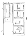
Referring to FIG. 1, a system 10 includes a processor 12 that is configured as a multi-processor 12. That is, the processor 12 includes a plurality of processors 14 a through 14 g. In the embodiment shown, the processor 14 a is a general-purpose processor and processors 14 b-14 g are microcoded processors (hereinafter, microengines 14 b-16 g), each with multiple hardware controlled threads that can be simultaneously active and independently work on a task. In the embodiment shown, there are six microengines; however, a different number of microengines could be used. Each of the six microengines 14 b-16 g is capable of processing multiple execution threads.
The processor 14 a performs general-purpose computer type functions such as handling protocols, exceptions, extra support for microengine processing when a more detailed processing is needed. In one embodiment, the processor 14 a is a StrongARM (ARM is a trademark of ARM Limited, United Kingdom) core based architecture. The processor 14 a (hereinafter, “the core processor” 14 a) includes an internal CPU 16 coupled to an internal core memory 17 that includes an instruction memory (shown as an instruction cache) 18, a data memory (shown as a data cache) 20 and read/write buffers 22.
The multi-processor 12 is coupled to a first peripheral bus (shown as a PCI bus) 24, a second peripheral bus referred to as an I/O bus 26 and a memory system 28. The processors 14 a-14 g operate with shared resources including the memory system 28, a PCI bus interface 30 and an I/O bus interface 32. The PCI bus interface 30 provides an interface to the PCI bus 24. The I/O bus interface 32 is responsible for controlling and interfacing the processor 12 to the I/O bus 26. The memory system 28 includes a Synchronous Dynamic Random Access Memory (SDRAM) 28 a, which is accessed via an SDRAM controller 34 a, a Static Random Access Memory (SRAM) 28 b, which is accessed using an SRAM controller 34 b, and a nonvolatile memory (shown as a FlashROM) 28 c that is used for boot operations and also accessed using the SRAM controller 34 b. The SDRAM 34 a and SDRAM controller 34 b are typically used for processing large volumes of data, e.g., in a network application, processing of payloads from network packets. The SRAM 28 b and SRAM controller 34 b are used in a for low latency, fast access tasks, e.g., accessing look-up tables, memory for the processor 14 a, and so forth. The processors 14 can execute memory reference instructions to either the SDRAM controller 34 a or the SRAM controller 34 b.
The multi-processor processor 12 interfaces to at least one I/O device 36 over the I/O Bus 26. In the embodiment shown, the I/O device 36 is a network interface device that couples the multiprocessor 12 to a network 38. The device 36 may include a plurality of ports to be serviced by the multiprocessor 12. Other devices, such as a host computer 40, which is coupled to the PCI bus 24, are also serviced by the multi-processor 12.
Each of the functional units of the processor 12 are coupled to one or more internal buses. The internal buses include an internal core bus 42 (labeled “AMBA”) for coupling the processor 14 a to the memory controllers 34 a, 34 b and to an AMBA translator 44. The processor 12 also includes a private bus 46 that couples the microengines 14 b-14 g to the SRAM controller 34 b, AMBA translator 44 and the I/O bus interface 32. A memory bus 48 couples the memory controllers 34 a, 34 b to the bus interfaces 30, 32 and the memory system 28.
Referring to FIG. 2, a high-level view of multi-processor software 50 that executes on the multi-processor 12 is depicted. The software 50 includes core processor software 52 that executes on the core processor 14 a and microengine microprograms (or microcode) 54 a-54 f that executes on the respective microengines 14 b-14 g. As illustrated with reference to the microcodes 54 a and 54 b, the microcode in each of the microengines can comprise multiple threads of execution, threads 56. The core processor software 52 includes an operating system 58 through which the core processor 14 a can call functions to operate on the microengines 14 b-14 g. The core processor 14 a can use any supported operating system, preferably a real-time operating system. For the core processor implemented as a StrongARM architecture, operating systems such as MicrosoftNT real-time, VXWorks and uCOS, a freeware operating system available over the Internet, can be used. The core processor software 52 further includes application software 60, communications software 62 and device drivers 64, which includes a device driver for the microengines 14 b-14 g. The software 52 further includes a microengine loader 66 to load the microcode 54 a-54 g into respective ones of the microengines 14 b-14 g, as will be described more fully below.
Referring to FIG. 3, an exemplary one of the microengines 14 b-14 f, the microengine 14 b, is shown. The microengine 14 b includes an instruction memory (or “control store”) 70 for storing microinstructions of a corresponding one of the microcodes 54, the microcode 54 a. The microcode 54 a is loadable by the core processor 14 a (from FIG. 1), as will be described more fully below. The microengine 14 b also includes control logic 72. The control logic 72 includes an instruction decoder 73 and program counter units 72 a-72 d. The four program counters are maintained in hardware. The microengine 14 b also includes context event switching logic 74. The context event switching logic 74 receives messages from each one of the share resources, e.g., SRAM 28 b, SDRAM 28 a, or processor core 14 a, control and status registers, and so forth. These messages provide information on whether a requested function has completed. Based on whether or not the function requested by a thread has completed and signaled completion, the thread needs to wait for that complete signal, and if the thread is enabled to operate, then the thread is place on an available thread list (not shown). As was illustrated in FIG. 2, the microengine 14 b can have multiple threads of execution available.
The microengine 14 b also includes an execution box (EBOX) data path 76 that includes an arithmetic logic unit (ALU) 76 a and a general purpose register (GPR) set 76 b. The ALU 76 a performs arithmetic and logical functions as well as shift functions.
The microengine 14 ba further includes a write transfer register file 78 and a read transfer register file 80. The write transfer register file 78 stores data to be written to a resource. The read transfer register file 80 is for storing return data from a resource. Subsequent to or concurrent with the data arrival, an event signal from the respective shared resource, e.g., memory controllers 34 a, 34 b, or core processor 14 a, will be provided to the context event arbiter 74, which in turn alerts the thread that the data is available or has been sent. Both transfer register files 78, 80 are connected to the EBOX 76 through a data path. In the described implementation, each of the register files includes 64 registers.
The functionality of the microengine threads is determined by the microcode loaded (via the core processor 14 a) for a particular user's application into each microengine's control store 70. For example, when the processor 12 is a network processor, one of the microengine threads may be assigned to serve as a receive scheduler thread and another as a transmit scheduler thread, and other threads on other microengines may be configured as receive processing threads and transmit processing (or “fill”) threads. Other thread task assignments include a transmit arbiter and one or more core communication threads. Once launched, a thread performs its function independently.
Referring to FIG. 4, another embodiment of the system 10 shown as a development system environment 10′, includes a development station 90 connected to the network 38 by a second network interface device 91. The development station 90 is configured with core processor application software tools 92 for generating core processor application program or programs 60 (FIG. 2) and microengine microcode development tools 94 for generating the microcode 54. The microengine microcode development tools 94 include a microcode assembler 96 and a microcode linker 98, collectively, microcode development software 99. Although not shown, the development station 90 includes a Graphical User Interface (GUI) through which a user (i.e., a programmer or code developer) may enter commands and other input data, such as source code, and further includes any other software that would allow the development station to communicate over the network 38 with either the processor 12 or host computer like the PCI host computer 40. Communications from the network 38 to the PCI bus are supported by a third network interface device 100.
Referring to FIGS. 2 and 4, various software components of the environment—the operating system 58, the core processor application 60, the microengine loader 66, the development tools 90 and the communications software 62 in the core processor and the development system (not shown)—cooperate to enable the core processor 14 b to configure the microengines 14 b-14 g for operation with appropriate user-defined functionality. A code object for the application software 60 for the core processor 14 a is generated from user-defined source code entered using the development tools 92. Once generated, the application code object is provided to the boot memory 28 c. At initialization time, the code object for the application 60 is loaded into either SDRAM 28 a or internal core memory 18, or both, for execution. A single code object corresponding to all of the microcode 54 for the microengines 14 b-14 g is generated from user-defined source code entered using the development tools 94. Once generated, the code object may be stored in a file or buffer in storage (or host memory) and loaded into processor DRAM memory 28 a by the application, or provided to the Flash memory 28 c by the development station 90. Thus, there are a number of different ways to move the microcode object, once generated, into the memory 28 of the processor 12. The application 60 directs the loader 66 to load the microcode from the memory 28 into the control stores 70 a-70 f of microengines 14 b-14 g. The application may do so at any time. Typically, the application is defined to load the microcode 54 at initialization time. It may load the microcode 54 into only one or more (or all) of the microengines at the same time, or one at a time. The microcode 54 may be the same for all of the microengines 14 b-14 g, or it may be different for one or more of the microengines 14 b-1 g, depending on the functionality that the user wishes to assign to each of them (and their threads).
It is understood that the development station and its tools are only required when developing, modifying or debugging code. Although the development station is depicted as a network client, it could be a console connected to the processor 12 via a serial port connection (not shown).
FIG. 5 depicts a high-level view of the microcode development process 110, illustrating a process 112 corresponding to the microcode development software 90 and some of the details of user input 114 and process output 116. As shown, the user input is in the form of a source code. The process 112 includes an assembler process 118 and a linker process 120. The assembler process 118 produces a list file (*.list file) from the source code. The list file is provided to the linker process 120, which generates the process output 116 in the form of a code object 114. The microcode code object 116 includes a plurality of images 120 a-120 f, each one corresponding to a different one of the microengines 14 b-14 g.
Thus, a user provides the source code 114 to the assembler 118. Each section of the source code 114 identifies that it belongs to a given program image through an image name declaration. The code sections designated for different microengines have different image names. Image name definition associates a name with the content of the assembler *.list file in the output object file. That is, it identifies the image within the object file, thus allowing referencing to particular section of the object file by name by the loader 66. The image name is unique for all input files that are to be linked. The image name is defined in the microcode source file (*.uc) using a .image_name keyword. If the .image_name is not specified in the source file, then the image name will be the name of the list file excluding any directory and file extension. Format for the image name declaration in the source (*.uc) and output (*.list) files is “.image_name name”.
Address sharing between the microengine images and a core image is achieved by declaring variables as import variables using an import variable keyword in the microcode source file (*.uc) prior to the variables being used. The assembler generates a list of microword addresses and field bit positions within the microword where the variables are used and provides the information in its output file (*.list). Format for the import variable declaration in the assembler source (*.uc) file is “.import_var variable_name variable_name . . . ”
The assembler process 118 assembles all of the code for a microcode image at one time. More specifically, it assembles all images sequentially with one build request. The .image_name and .import_var statements are processed as they are encountered. The assembler saves code locations at which the names indicated by the import_var statement are encountered.
Referring to FIG. 6, an .import_var variable 130 can be split such that half of the variable is placed in first instruction 132, and the other half of the import variable is in a second instruction 134. To indicate which half of the variable goes to which of the instructions 132, 134, the following language syntax is used:
immed_w0[reg1, parameter1]//insert bits 31:16
immed_w1[reg1, parameter1>>16]//insert bits 15:0
Thus, the list file generated by the assembler 118 includes for a given image an image name, and for each import variable, instruction location(s), field size and bit location within the instruction(s). It also identifies which bits of the variable go to the instruction field.
Returning to FIG. 5, the linker process 120 accepts the list of microengine images generated by the assembler and combines the images into the single code object 116. The linker stores the code object in a microcode object file (*.uof file) or as a data buffer in memory in a format that is understood by the loader 66. Each of the images 120 a-12 f includes declaration and variable information 122 a-122 f, respectively, following by an instruction code 124 a-124 f. The declaration and variable information 122 a-122 f specifies image name, import variable names, import variable instruction locations, field size and shift amounts, as described earlier.
The code object 116 thus includes image objects 120 a-120 f for all processors in the multiprocessor configuration other than core processor, that is, the microengines 14 b-14 g. The code object 116 is loadable by the core image, running on the core processor 14 a, utilizing library functions of the loader 66, as will be described in further detail.
Referring to FIG. 7, an exemplary loading process 140 performed by the loader is as follows. The loader process 140, copies 142 the microcode object into local (core) memory. The loader process 140 binds 143 the import variables to parameter values by determining 144 the parameter values to be assigned to the import variables and inserting 145 the parameter values into the instruction code image at the instruction locations for the import variables (as specified by the import variable location, bit field and shift information). The loader process 140 writes 146 each of the images in the object to the corresponding microengine instruction code storage area (that is, the control stores 70).
The application can also use the loader to stop and start the microengines as needed to modify (for purposes of bug correction, code enhancements, functionality changes) the microcode in its entirety or a portion thereof. To modify an entire image for one or more of the microengines 14 b-14 g, a revised source code is provided as input to the development station, which generates a revised object file including the revised image or images, and the revised images are again loaded in the same manner as described with reference to FIG. 7. The only difference between the first load and subsequent loading of modified images is that the microengine to receive a modified engine must be placed in a paused or reset state prior to modified image being written to the microengine and then removed from the paused or reset state after the microcode image has been written to the designated control store.
Referring back to FIGS. 2-4, the application 60 places the microengine 14 b in a paused or reset state by calling an appropriate function in the device drivers 64 (more specifically, in the microengine device driver). The development station tools 94 may include functions that the development station 90 can use to stop or reset the microengine. If the development station 90 performs this task, it notifies the application 60 that the microengine 14 b is being placed in a paused or reset state.
In addition, as will be described, the application 60 can modify a portion of an image stored in one or more of the control stores 70. In one embodiment, the portion corresponds to a page.
To perform a modification on a single page basis, the microcode source code is further divided into pages. That is, the original source code identifies the start of a page with a .page declaration. As illustrated in FIG. 8, for a page modification, some code instructions in a page are modified at the source code file to produce new (that is, revised) pages 150 a-150 g. The new page is retrieved (from memory) by the application (indicated by arrow labeled “1”). The new page only may be updated with variable parameter values 152 during the binding process (indicated by arrow labeled “2”) as previously described, and written to a location corresponding of the page in the image in the corresponding control stores 54 of the microengines (indicated by arrows “3” and “4”).
As stated earlier, typically the core processor 14 a is programmed to load each control store 70 upon system initialization. Preferably, it uses the microengine loader 66 to load microcode images generated by the microcode linker to the appropriate microengines, as described above with reference to FIG. 7. In the preferred embodiment, the loader 66 is a library of C functions that loads the program images from an object file into a control store, updates images with application parameter values and initializes the microengine registers.
Exemplary application programming interfaces (API) for the loader 66 are summarized in Table 1 below.
API Function
UcLo_InitLib Initialize the loader library.
UcLo_LoadObjFile Load microcode object from a
file to core memory.
UcLo_CopyObjFile Copy microcode object from a
file to buffer.
UcLo_mapObjAddr Maps core memory location to
microcode object.
UcLo_DelObj Removes all references to a
microcode object.
UcLo_BindSymbol Produces an association between
a core application value and a
microcode symbol.
UcLo_WriteUImageAll Write all microcode images to
the appropriate microengines.
UcLo_WriteUImage Write a specific microcode
image to its assigned
microengine.
UcLo_WriteUImagePage Writes a specified page of
microcode image to an
appropriate microengine.
UcLoPci_Init Load microcode object via PCI
bus.
UcLO is a library of “C” functions that facilitate the loading of the microengine images, the management of the microengine variables and provides a communication link between the core application and the microengines.
The UcLo_InitLib function initializes the library and initialized microengine drivers. It is called by the core application prior to calling any of the other library functions. The library allocates and manages resources to accommodate the object. The application calls UcLo_deleObj to remove any reference to the object and free resources allocated by the library.
The UcLo_LoadObjFile function loads the object file produced by the linker into the core processor's memory. The UcLo_CopyObjFile loads the object from the object file to a buffer allocated by the library. The UcLo_MapObjAddr maps the memory location where the object file image resides to the object file. The UcLo_BindSymbol function associates a core application parameter value and a microcode import variable (or symbol). It initializes all occurrences of the specified import variable in the object file image to the 32-bit parameter value, or portion of the 32-bit value, as defined by the assembler. The UcLo_WriteUimageAll function writes all of the microcode images to the appropriate microengines. The UcLo_WriteUimagePage writes a page of microcode image that is specified by the ImageName parameter to the appropriate microengine(s) starting at address 0. The function specifies the page number to be loaded, along with the ImageName and handle (pointer reference to the loaded/mapped object). The UcLoPci_Init enables the loading of microcode object (*.uof) to the assigned microengines via the PCI channel using some type of communication mechanism, such as remote procedure call messages.
Alternatively, and as shown in FIG. 9, the core processor application 60 can program the control stores 70 without using the loader 66 by performing a series of reads and writes to the control store 70. First, the core application 60 places 160 each microengine into a reset or paused state. It then writes 162 to a microcode store address register in the Read Transfer registers 80 (FIG. 3) (via the AMBA translator 44, from FIG. 1) with a control store address, making certain that the control store enable bit in the register is set. It then writes 164 an instruction to a microcode store data register in the Rd Transfer registers 80 (again, using the AMBA translator 44) to load the instruction into the control store. More specifically, once the address and instruction has been written to the appropriate registers, the microengine controller 72 (FIG. 3) transfers the instruction to the control store at the designated address. The core application then determines 166 if there is another instruction to be written. If so, the core application returns to 160 to repeat the instruction load for the next instruction. If there are no additional instructions to be loaded, the core application removes 166 the microengine from the reset or paused state.
Additions, subtractions, and other modifications of the preferred embodiments of the invention will be apparent to those practiced in this field and are within the scope of the following claims.

Claims (15)

What is claimed is:
1. A method of executing an application by a processor in a multi-processor configuration of processors, each having an associated instruction memory, comprising:
receiving object code that includes an image for at least one other processor in the multi-processor configuration of processors;
binding an import variable in the image to a parameter value;
storing the image for the at least one other processor into the associated instruction memory; and
modifying the image stored in the associated instruction memory wherein modifying comprises:
receiving revised object code including a revised version of the image and
storing the revised image in the associated instruction memory.
2. The method of claim 1, wherein binding comprises:
inserting the parameter value into at least one instruction in the image.
3. The method of claim 1, further comprising:
calling a library function to insert the parameter value into the at least one instruction in the image.
4. The method of claim 1, wherein storing comprises:
calling a library function to load the image into the associated instruction memory.
5. The method of claim wherein modifying further comprises:
modifying a portion of the image.
6. The method of claim wherein the portion corresponds to a page.
7. The method of claim 1, wherein storing the revised image comprises:
using library functions to store the revised object code in a local memory, insert parameter values in instructions in the revised image and load the revised image with the newly inserted parameter values from the local memory into the associated instruction memory.
8. The method of claim 1, wherein modifying further comprises:
placing the processor into a paused state.
9. The method of claim 1, wherein the object code includes a parameter having a value that is included in fields of more than one instruction.
10. The method of claim 1, further comprising:
receiving object code that includes images for each of the other processors in the multi-processor configuration of processors; and
storing the images for the other processors in each respective associated instruction memory.
11. The method of claim 1, wherein the images are identical for the other processors.
12. A processor comprising:
a multiprocessor configuration of processors;
an instruction memory in each of the processors; and
a first one of the processors in the multiprocessor configuration of processors being operated to receiving object code that includes an image for at least one other processor in the multi-processor configuration of processors; to bind an import variable in the image to a parameter value; to store the image in the instruction memory of at least one other processor in the multiprocessor configuration of processors while executing an application program image; and
to modify the image stored in the associated instruction memory wherein modifying comprises:
to receive revised object code including a revised version of the image and
to store the revised image in the associated instruction memory.
13. The processor of claim 12, wherein the first one of the processors is a general purpose processor, the code image corresponds to microcode and the at least one other processor is a microengine that executes the microcode.
14. An article comprising a computer-readable medium which stores computer-executable instructions for executing an application by a processor in a multi-processor configuration of processors, each having an associated instruction memory, the instructions causing a computer to:
receive object code that includes an image for at least one other processor in the multi-processor configuration of processors;
bind an import variable in the image to a parameter value;
store the image for the at least one other processor into the associated instruction memory; and
modifying the image stored in the associated instruction memory wherein modifying comprises:
receiving revised object code including a revised version of the image and
storing the revised image in the associated instruction memory.
15. The article of claim 14, wherein the image corresponds to microcode and the at least one other processor is a microengine that executes the microcode.
US09/753,084 2000-12-28 2000-12-28 Multiple image dynamic bind and load procedure for a multi-processor Expired - Fee Related US6684395B2 (en)

Priority Applications (1)

Application Number Priority Date Filing Date Title
US09/753,084 US6684395B2 (en) 2000-12-28 2000-12-28 Multiple image dynamic bind and load procedure for a multi-processor

Applications Claiming Priority (1)

Application Number Priority Date Filing Date Title
US09/753,084 US6684395B2 (en) 2000-12-28 2000-12-28 Multiple image dynamic bind and load procedure for a multi-processor

Publications (2)

Publication Number Publication Date
US20030046358A1 US20030046358A1 (en) 2003-03-06
US6684395B2 true US6684395B2 (en) 2004-01-27

Family

ID=25029087

Family Applications (1)

Application Number Title Priority Date Filing Date
US09/753,084 Expired - Fee Related US6684395B2 (en) 2000-12-28 2000-12-28 Multiple image dynamic bind and load procedure for a multi-processor

Country Status (1)

Country Link
US (1) US6684395B2 (en)

Cited By (8)

* Cited by examiner, † Cited by third party
Publication number Priority date Publication date Assignee Title
US20040049770A1 (en) * 2002-09-10 2004-03-11 Georgios Chrysanthakopoulos Infrastructure for generating a downloadable, secure runtime binary image for a secondary processor
US20050210457A1 (en) * 2004-03-22 2005-09-22 Intel Corporation Debug system having assembler correcting register allocation errors
US20060026568A1 (en) * 2001-07-05 2006-02-02 Microsoft Corporation System and methods for providing versioning of software components in a computer programming language
US20070130565A1 (en) * 2005-12-01 2007-06-07 Samsung Electronics Co., Ltd. System and method for a pseudo DLL linker
US20090119495A1 (en) * 2007-11-05 2009-05-07 Mukund Khatri Architectural Enhancements to CPU Microde Load Mechanism for Information Handling Systems
US7664823B1 (en) * 2003-09-24 2010-02-16 Cisco Technology, Inc. Partitioned packet processing in a multiprocessor environment
US20100299660A1 (en) * 2009-05-21 2010-11-25 Microsoft Corporation Dynamic binding directed by static types
US8001523B1 (en) 2001-07-05 2011-08-16 Microsoft Corporation System and methods for implementing an explicit interface member in a computer programming language

Families Citing this family (4)

* Cited by examiner, † Cited by third party
Publication number Priority date Publication date Assignee Title
US20050273776A1 (en) * 2004-06-08 2005-12-08 Intel Corporation Assembler supporting pseudo registers to resolve return address ambiguity
US8438549B1 (en) * 2009-09-15 2013-05-07 Sandia Corporation Data processing with microcode designed with source coding
US20150128117A1 (en) * 2013-11-07 2015-05-07 Netronome Systems, Inc. Linker that statically allocates non-memory resources at link time
CN112995069A (en) * 2019-12-16 2021-06-18 华为技术有限公司 Instruction writing method and device and network equipment

Citations (4)

* Cited by examiner, † Cited by third party
Publication number Priority date Publication date Assignee Title
US5452461A (en) * 1989-04-28 1995-09-19 Hitachi, Ltd. Program parallelizing apparatus capable of optimizing processing time
US5745058A (en) * 1996-10-21 1998-04-28 International Business Machines Corporation Method and system for compressing microcode to be executed within a data processing system
US5748963A (en) * 1995-05-12 1998-05-05 Design Intelligence, Inc. Adaptive binding
US6230312B1 (en) * 1998-10-02 2001-05-08 Microsoft Corporation Automatic detection of per-unit location constraints

Patent Citations (5)

* Cited by examiner, † Cited by third party
Publication number Priority date Publication date Assignee Title
US5452461A (en) * 1989-04-28 1995-09-19 Hitachi, Ltd. Program parallelizing apparatus capable of optimizing processing time
US5748963A (en) * 1995-05-12 1998-05-05 Design Intelligence, Inc. Adaptive binding
US5745058A (en) * 1996-10-21 1998-04-28 International Business Machines Corporation Method and system for compressing microcode to be executed within a data processing system
GB2319366A (en) * 1996-10-21 1998-05-20 Ibm Microcode compression
US6230312B1 (en) * 1998-10-02 2001-05-08 Microsoft Corporation Automatic detection of per-unit location constraints

Non-Patent Citations (1)

* Cited by examiner, † Cited by third party
Title
IBM Technical Disclosure Bulletin, "Retrofix: Creating Fix Control Statements for Monolithic Program Objects", vol. 37, No. 3, pp.: 449-450, Mar. 1994. *

Cited By (15)

* Cited by examiner, † Cited by third party
Publication number Priority date Publication date Assignee Title
US8001523B1 (en) 2001-07-05 2011-08-16 Microsoft Corporation System and methods for implementing an explicit interface member in a computer programming language
US20060026568A1 (en) * 2001-07-05 2006-02-02 Microsoft Corporation System and methods for providing versioning of software components in a computer programming language
US7873958B2 (en) * 2001-07-05 2011-01-18 Microsoft Corporation System and methods for providing versioning of software components in a computer programming language
US7076774B2 (en) * 2002-09-10 2006-07-11 Microsoft Corporation Infrastructure for generating a downloadable, secure runtime binary image for a secondary processor
US20040049770A1 (en) * 2002-09-10 2004-03-11 Georgios Chrysanthakopoulos Infrastructure for generating a downloadable, secure runtime binary image for a secondary processor
US7664823B1 (en) * 2003-09-24 2010-02-16 Cisco Technology, Inc. Partitioned packet processing in a multiprocessor environment
US8307053B1 (en) 2003-09-24 2012-11-06 Cisco Technology, Inc. Partitioned packet processing in a multiprocessor environment
US20050210457A1 (en) * 2004-03-22 2005-09-22 Intel Corporation Debug system having assembler correcting register allocation errors
US7478374B2 (en) 2004-03-22 2009-01-13 Intel Corporation Debug system having assembler correcting register allocation errors
US20070130565A1 (en) * 2005-12-01 2007-06-07 Samsung Electronics Co., Ltd. System and method for a pseudo DLL linker
US7735075B2 (en) * 2005-12-01 2010-06-08 Samsung Electronics Co., Ltd. System and method for a pseudo dynamic link library (DLL) linker for a monolithic image in a wireless device
US20090119495A1 (en) * 2007-11-05 2009-05-07 Mukund Khatri Architectural Enhancements to CPU Microde Load Mechanism for Information Handling Systems
US7882333B2 (en) 2007-11-05 2011-02-01 Dell Products L.P. Architectural enhancements to CPU microcode load mechanism using inter processor interrupt messages
US20100299660A1 (en) * 2009-05-21 2010-11-25 Microsoft Corporation Dynamic binding directed by static types
US9075667B2 (en) * 2009-05-21 2015-07-07 Microsoft Technology Licensing, Llc Dynamic binding directed by static types

Also Published As

Publication number Publication date
US20030046358A1 (en) 2003-03-06

Similar Documents

Publication Publication Date Title
US6341345B1 (en) Mixed-endian computer system that provides cross-endian data sharing
US5729748A (en) Call template builder and method
US7533246B2 (en) Application program execution enhancing instruction set generation for coprocessor and code conversion with marking for function call translation
US5640528A (en) Method and apparatus for translating addresses using mask and replacement value registers
US5923863A (en) Software mechanism for accurately handling exceptions generated by instructions scheduled speculatively due to branch elimination
US7603540B2 (en) Using field programmable gate array (FPGA) technology with a microprocessor for reconfigurable, instruction level hardware acceleration
US6944850B2 (en) Hop method for stepping parallel hardware threads
US5619680A (en) Methods and apparatus for concurrent execution of serial computing instructions using combinatorial architecture for program partitioning
EP0752646B1 (en) Data access implementation of device driver interface
JP3758732B2 (en) System and method for executing endian task
US20060259744A1 (en) Method for information processing
US5644746A (en) Data processing apparatus with improved mechanism for executing register-to-register transfer instructions
US7200840B2 (en) Method and apparatus for enabling access to global data by a plurality of codes in an integrated executable for a heterogeneous architecture
EP0859978A1 (en) A system and method for fast context switching between tasks
JP2007534066A (en) Multicomputer architecture with replicated memory field
JPH06266683A (en) Parallel processor
US6684395B2 (en) Multiple image dynamic bind and load procedure for a multi-processor
JPH0760380B2 (en) Program call device
KR100272937B1 (en) Microprocessor and multiprocessor system
US5764962A (en) Emulation of asynchronous signals using a branch mechanism
US6330691B1 (en) Use of dynamic translation to provide breakpoints in non-writeable object code
US5649142A (en) Method and apparatus for translating addresses using mask and replacement value registers and for accessing a service routine in response to a page fault
Bodenstab et al. The UNIX system: UNIX operating system porting experiences
EP1987490B1 (en) Method and apparatus for moving area operator definition instructions statements within control flow structures
US7065754B1 (en) Method and apparatus for switching between multiple implementations of a routine

Legal Events

Date Code Title Description
AS Assignment

Owner name: INTEL CORPORATION, CALIFORNIA

Free format text: ASSIGNMENT OF ASSIGNORS INTEREST;ASSIGNORS:JOHNSON, DESMOND R.;HOOPER, DONALD F.;GUILFORD, JAMES D.;REEL/FRAME:012605/0507

Effective date: 20010430

FEPP Fee payment procedure

Free format text: PAYER NUMBER DE-ASSIGNED (ORIGINAL EVENT CODE: RMPN); ENTITY STATUS OF PATENT OWNER: LARGE ENTITY

Free format text: PAYOR NUMBER ASSIGNED (ORIGINAL EVENT CODE: ASPN); ENTITY STATUS OF PATENT OWNER: LARGE ENTITY

FPAY Fee payment

Year of fee payment: 4

FPAY Fee payment

Year of fee payment: 8

REMI Maintenance fee reminder mailed
LAPS Lapse for failure to pay maintenance fees
STCH Information on status: patent discontinuation

Free format text: PATENT EXPIRED DUE TO NONPAYMENT OF MAINTENANCE FEES UNDER 37 CFR 1.362

FP Lapsed due to failure to pay maintenance fee

Effective date: 20160127