CROSS REFERENCE TO RELATED APPLICATIONS
This application is based on and claims priority under 35 U.S.C. §119 with respect to a Japanese Patent Application 2001-085651, filed on Mar. 23, 2001, the entire content of which is incorporated herein by reference.
FIELD OF THE INVENTION
This invention generally relates to a displacement sensor.
BACKGROUND OF THE INVENTION
A displacement sensor is disclosed in, for example, a Japanese Patent Laid-Open Publication No. 7(1995)-22214. Referring to FIGS. 2(A) and 2(B), a slider 201 displaced by a displacement of an object to be detected is disposed so as to slide on a resistor 202. A ground (GND) terminal 205 connected to a ground (GND) 206 and an electric power source terminal 203 connected to an electric power source 204 are connected to both ends of the resistor 202, respectively. The resistor 202 includes a lower resistance layer 208 accumulated on a flat surface of a substrate 207, and an upper resistance layer 209 accumulated on the lower resistance layer 208.
According to the displacement sensor with the aforementioned structure, the lower resistance layer 208 is made of a material in which carbon black and carbon fiber 210 are dispersed in a synthetic resin. Therefore, there may be a case where an axial direction of the carbon fiber 210 resides in a direction perpendicular to the sliding direction along which the slider 201 slides. For example, as shown in FIG. 2(A), there may be a case where the axial direction of the carbon fiber 210 and the sliding direction of the slider 201 reside continuously in the same directions. Particularly, referring to FIG. 2(B), a large amount of carbon fiber 210 is contained in the lower resistance layer 208. The axial direction of the carbon fiber 210 extends in the direction perpendicular to the sliding direction of the slider 201.
Referring to FIG. 2(B), a large amount of carbon fiber 210 is found in the lower resistance layer 208 so that an irregular pattern may be formed on the lower resistance layer 208 along the sliding direction of the slider 201. As a result of this, the irregular pattern may be also formed on the upper resistance layer 209 along the sliding direction of the slider 201.
When the slider 201 slides on the upper resistance layer 209, abrasion powder is produced. The abrasion powder is deposited in concave portions formed on the upper resistance layer 209 so as to form an abrasion powder deposited portions 211. The abrasion powder deposited portions 211 (i.e., the concave portions) extend along the direction perpendicular to the sliding direction of the slider 201 on the upper resistance layer 209. Therefore, while the slider 201 slides on the abrasion powder deposited portions 211, the electric conduction between the slider 201 and the resistor 202 is disconnected or the resistance therebetween is increased. As a result of this, signal noise may be increased and detection accuracy of the displacement sensor may be deteriorated with elapse of time.
Accordingly, the above disclosed displacement sensor is still susceptible of certain improvements with respect to providing a contact-type displacement sensor for maintaining a high level of accuracy, especially with an elapse of time.
According to a variable resistor or displacement sensor disclosed in Japanese Patent Laid-Open Publications No. 8 (1996)-285516 and No. 8 (1996)-236320, and in a Japanese Utility Model Publication No. 2575538, when a rotor to which the slider is attached is inclined, the slider may undergo excessive elastic or plastic deformation due to the poor function of a protective member, i.e., a clearance formed between the slider and the resistor is located at a position apart from the slider. That is, if the rotor is rotated in an inclined condition in a state where the slider is disposed at an outer periphery of the rotor and the slider protective member is disposed at an inner periphery of the rotor and vice versa, the slider may be compressed at an amount equal to or greater than a difference between “a set height of the slider” and “a height of the protective member” at a certain rotational position of the rotor. This means that the protective member may not function effectively.
Accordingly, the above disclosed displacement sensors are still subjected to certain improvement with respect to supplying a protective member for assuring a clearance between a slider and a resistor.
Further, a Japanese Utility Model. Publication No. 5 (1993)-8920 discloses a structure in which a stopper for restricting the deformation of the slider is provided to the slider itself. According to the structure, however, the stopper is made of a conductive material. Therefore, when the stopper and the resistor are brought into contact with each other, the slider and the resistor may be electrically short-circuited. Further, an erroneous detection signal or a noise may be outputted.
Accordingly, the above disclosed displacement sensor is still subjected to certain improvement with respect to preventing a slider and a resistor from being electrically short-circuited.
Further, according to one of known displacement sensors or one of known variable resistors, a rotational member such as a rotor is crimped or a speed nut or a snap ring is employed as a component for rotatably supporting the rotational member in a housing and for preventing the rotational member from being removed in an axial direction. However, predetermined equipments or tools are required for crimping the rotational member. Further, the number of components for the displacement sensor or the variable resistor may be increased by adding components including speed nuts. This may lead to a cost increase.
SUMMARY OF THE INVENTION
The present invention provides a displacement sensor which is a contact-type displacement sensor for detecting a displacement of an object to be detected based on a change of a resistance value. The displacement sensor includes a resistor having a surface to be slid, a slider sliding on the surface to be slid in a predetermined direction (i.e., a predetermined direction, for example in one direction) in accordance with the displacement of the object to be detected, and an irregular pattern formed on the surface to be slid and including convex portions and concave portions continuously formed along a direction crossing or perpendicular to a sliding direction of the slider.
According to this displacement sensor, the irregular pattern can be formed on the surface of the resistor, without adding filler, carbon fiber, or the like, to the resistor. A stable contact can hence be achieved between the slider and the convex portions formed on the resistor, and accordingly, a stable conduction can be maintained between the slider and the resistor. Therefore, signal noise can be effectively decreased and detection accuracy can be maintained with an elapse of time, and accordingly, durability can be prolonged.
BRIEF DESCRIPTION OF THE DRAWING FIGURES
The foregoing and additional features and characteristics of the present invention will become more apparent from the following detailed description considered with reference to the accompanying drawing figures wherein:
FIG. 1(A) is a diagram for illustrating a structure of a displacement sensor according to a first embodiment of the present invention, and FIG. 1(B) is a cross-sectional view taken along a line B—B of FIG. 1(A);
FIGS. 2(A) and 2(B) are diagrams for illustrating a structure of a known displacement sensor,
FIGS. 3(A) to 3(C) are exploded assembly diagram for illustrating an example of applying the displacement sensor according to the first embodiment of the present invention;
FIG. 4 is a diagram for illustrating a structure of a displacement sensor according to a second embodiment of the present invention;
FIG. 5 is an exploded view for illustrating a structure for assembling a slider included in the displacement sensor shown in FIG. 4;
FIG. 6 is an assembly diagram for illustrating a structure for assembling the slider included in the displacement sensor shown in FIG. 4;
FIG. 7 is a diagram viewed along an arrow B of FIG. 6;
FIG. 8 is a side view for illustrating a state where the slider included in the displacement sensor shown in FIG. 4 is in slide contact with a resistor;
FIGS. 9(A) and 9(B) are diagrams for illustrating a structure of a displacement sensor according to a third embodiment of the present invention, and FIG. 9(B) is a side view showing a main portion of FIG. 9(A);
FIG. 10 is an exploded view of the displacement sensor shown in FIG. 9
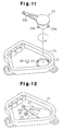
FIG. 11 is an exploded view for illustrating a structure of a displacement sensor according to a fourth embodiment of the present invention; and
FIG. 12 is a view for illustrating the operation of the displacement sensor shown in FIG. 11.
DETAILED DESCRIPTION OF THE INVENTION
In a preferable embodiment of the present invention, an irregular pattern is formed to bring convex portions of the irregular pattern into contact with a slider at plural portions. Therefore, even when abrasion powder produced by a sliding movement of the slider is formed on the surface to be slid of the resistor, high electric conductivity is assured between the slider and the resistor, i.e., the surface to be slid.
A displacement sensor according to the present invention is preferably applied to a displacement sensor in which the slider is constituted so as to slide in a predetermined direction, for example, in one direction or interchangeable with another direction.
The displacement sensor of the present invention is applicable to a straight-moving type displacement sensor (a variable resistor), in which the slider basically exhibits parallel movements, or a rotational-type displacement sensor, in which the slider basically exhibits circular movement. In addition, the irregular pattern can be formed on the resistor so that the pattern has a proper circular arc shape.
In a preferable embodiment of the present invention, the resistor is provided with a single layer or a plurality of layers.
Further, in a preferable embodiment of the present invention, the irregular pattern is formed in a range being wider than the width of the slider and is continuously formed in a range being wider than an operation range or a sliding range of the slider along a sliding direction of the slider. Concave portions are hence continuously formed outside the operation range of the slider, as well. Therefore, the abrasion powder is pushed out along the concave portions of the irregular pattern so that the abrasion powder cannot be easily accumulated within the operation range of the slider.
Further, in a preferable embodiment of the present invention, it is preferable to directly polish the substrate of the resistor for providing the irregular pattern when the substrate of the resistor is a common circuit substrate made of glass fiber, epoxy resin and the like. Further, when the resistor is directly printed on a molded substrate made of synthetic resin, the irregular pattern can be formed by using a mold which has been provided with the irregular pattern on its surface beforehand. Therefore, a step for polishing the substrate can be omitted. Further, this method can effectively avoid an increase in cost.
Further, in a preferable embodiment of the present invention, the concave portions are formed to have a depth of 3 μm or greater than that on the substrate so as to be sufficiently deep relative to the particle diameters of abrasion powder produced by the sliding action of the slider.
Further, in a preferable embodiment of the present invention, the cross-sectional shape of each concave portion and convex portion is either one of a circular arc shape, a triangular shape, a rectangular shape, a square shape, and a polygonal shape including a pentagonal shape.
The displacement sensor of the present invention is also employable as a variable resistor. Further, the displacement sensor can include a displacement member and a projection. The displacement member is assembled with the slider and is displaced in accordance with the displacement of the object to be detected. The projection is formed at an electrically insulative portion being adjacent to a slider mounting portion on the displacement member and being projected toward the resistor. The displacement member can be a rotor in the shape of a circular plate or in a ring shaped structure which is rotated in accordance with rotation of the object to be detected.
In such a case, the projection as a slider protective member for preventing the slider from undergoing excessive elastic deformation or plastic deformation is disposed being adjacent to the slider. Therefore, a sufficient height can be assured for the slider even when the member to which the slider is attached, for example, the rotor is deformed. The projection is attached to the insulator, for example to the rotor. Therefore, elastic short-circuit between the slider and the resistor can be prevented even when the projection comes in contact with the resistor.
Further, the displacement sensor can include a rotational member displaced in accordance with the displacement of the object to be detected, a claw formed on the rotational member, a housing accommodating the rotational member therein and rotatably supporting the rotational member, and a notch formed in the housing or in a member fixed to the housing and into which the claw is inserted. Therefore, the rotational member is secured to the housing so as not to come out thereof by a rotational operation of the rotational member at a predetermined angle after the claw is inserted into the notch upon assembling.
The housing or the member fixed to the housing further can include a return stopper or a projection for preventing the rotational member from being rotated in a reverse direction after the rotational member is operated to be rotated at the predetermined angle upon assembling.
Therefore, the rotational member is screwed into the housing and is rotatably assembled relative to the housing. The rotational member can be secured to the housing so as not to move in the axial direction.
Referring to FIGS. 1(A) and 1(B), a slider 1 displaced in accordance with a displacement of an object to be detected is disposed so as to slide on a resistor 2. A ground (GND) terminal 5 connected to a ground (GND) 6 and an electric power source terminal 3 connected to an electric power source 4 are connected to both ends of the resistor 2, respectively. The resistor 2 includes a substrate 7 and a resistance layer 8 accumulated on the substrate 7.
A fine irregular pattern 7 a is formed on the surface of the substrate 7 by a proper method including polishing and molding. The irregular pattern 7 a includes concave portions and convex portions continuously formed in a direction perpendicular to a sliding direction of the slider 1. A resistance layer 8 is accumulated by a method including printing on the surface of the substrate 7, i.e., on the irregular pattern 7 a.
An irregular pattern 2 a including grooves or continuous ridge lines extending along a sliding direction of the slider 1 is formed on the surface of the resistance layer 8 so as to coincide with the irregular pattern 7 formed on the surface of the substrate 1. The continuous ridge lines include concave portions and convex portions also continuously formed on the irregular pattern 2 a in a direction along the sliding direction of the slider 1. Further, at least two convex portions of the irregular pattern 2 a are formed per slider so as to be in contact with the slider 1. Further, the irregular pattern 2 a is formed to have a width larger than the width of the slider 1. Therefore, the convex and concave portions are continuously formed on the surface to be slid of the resistor 2 over wide width in a direction crossing or basically perpendicular to the sliding direction of the slider 1 (i.e., in a cross-sectional direction taken along a line B—B of FIG. 1(A)).
When the displacement sensor is employed, the slider 1 is slidably moved on the surface of the resistor 2, i.e., the resistance layer 8. In such a case, the slider 1 is always maintained to be in contact with the plural convex portions in the irregular pattern 2 a. The slidable movement of the slider 1 on the surface of the resistor 2, i.e., the resistance layer 8 produces abrasion powder so as to form an abrasion powder accumulated portions 9 in the concave portions of the irregular pattern 2 a. Since the abrasion powder accumulated portions 9 are formed along the sliding direction of the slider 1, sufficient conduction between the slider 1 and the resistor 2 is attained. Further, according to this displacement sensor of a first embodiment of the present invention, the irregular pattern 2 a is formed in a range wider than the width of the slider 1, i.e., outside the width of the slider 1. The abrasion powder is hence pushed into the concave portions located outside the width of the slider 1 by the slider 1 so as to be accumulated therein. Therefore, the abrasion powder is not easily accumulated in the operation range of the slider 1.
Therefore, according to the displacement sensor of the first embodiment of the present invention, high conducting performance can be attained between the slider 1 and the resistor 2. This prevents signal noise from being increased and detecting accuracy of the displacement sensor from being deteriorated with elapse of time. Further, durability can be prolonged.
Referring to FIGS. 3(A) to 3(C), the resistor 2 has a portion formed in the shape of a curve. In other words, the resistor 2 has a circular arc-shaped portion. The slider 1 shown in FIG. 3(C) is attached to a housing for the slidable movement on the irregular pattern 2 a of the resistor 2 shown in FIG. 3(A).
Next, description will be given about a displacement sensor to which the displacement sensor according to the first embodiment of the present invention described above is applied or the structure of the slider and the resistor featured in the displacement sensor of the first embodiment of the present invention is applicable.
Then, a displacement sensor according to a second embodiment of the present invention is described below with reference to FIGS. 4 through 8.
Referring to FIG. 4, the displacement sensor according to the second embodiment of the present invention is assembled by connecting a cover 11 a for holding a resistor 12 a to a housing 11 b for supporting a rotational shaft 18 of a rotor 14 to be rotated. A lever 10 is pivotably fixed to the rotor 14. A thrust washer 29 is interposed between the housing 11 b and the lever 10. A spring 19 is interposed between the housing 11 b and the rotor 14. A comb-shaped slider 13 is attached on the rotor 14. The slider 13 is biased toward the resistor 12 a by a biasing force of the spring 19. Further, a projection 14 a is shaped with the rotor 14.
A substrate 12 is accommodated in the cover 11 a. A seal 15 is interposed between the cover 11 and the substrate 12. The resistor 12 a having the irregular pattern 2 a, as shown in FIG. 1, is formed on the surface of the substrate 12 at the side of the slider 13. The resistor 12 a is electrically connected to a connector terminal 17 via a substrate terminal 16. A signal for representing a displacement of a rotational angle of the rotor 14 can be determined via the connector terminal 17.
Next, a structure for attaching the slider 13 to the rotor 14, and a structure between the slider 3 and the resistor 12 a will be described in detail.
Referring to FIGS. 5 to 7, a projection 14 a, a spring bearing 14 b, a securing pin 14 c, and a guide pin 14 d are formed being adjacent to one another at a slider mounting portion (i.e., a holding portion) on the rotor 14. The guide pin 14 d is arranged at a side portion of the securing pin 14 c. At least a portion of the rotor 14 to be in contact with the slider 13 and the projection 14 a are manufactured to be insulative.
On the other hand, an elastic portion 13 b is formed at a base portion of the slider 13. An oblong hole 13 c is defined at a central portion of the slider 13. The slider 13 is provided with a plurality of strap-shaped portions at a side opposed to the elastic portion 13 b relative to the oblong hole 13 c. A top end of each strap-shaped portion is formed in the shape of comb. The comb-shaped portions slide on the resistor 12 a.
When the slider 13 is mounted on the rotor 14, the securing pin 14 c is inserted into the oblong hole 13 c so as to bring the elastic portion 13 b to be in contact with the spring bearing 14 b and so as to push a reference end portion 13 a against the projection 14 a. The base portions of the plural strap-shaped portions are inserted between the securing pin 14 c and the guide pin 14 d, respectively.
Then, the securing pin 14 c and the guide pin 14 d are welded by a welding method including heat welding or ultrasonic welding so as to crimp and secure the slider 13 to the rotor 14.
Next, a slidable contact condition of the slider relative to the resistor is described below.
Referring to FIG. 8, a projecting portion 14 a, which is a rigid body, projects having a height (i.e., a height of a protective portion of the slider 13) h relative to a clearance between the rotor 14 and the resistor 12 a, i.e., relative to a set height H of the slider 13 having flexibility. Therefore, even when the clearance between the rotor 14 and the resistor 12 a is reduced, the slider 13 is prevented from being compressed at “H-h” or greater than that. This structure prevents the slider 13 from undergoing excessive elastic deformation or excessive plastic deformation. Further, the projection 14 a effectively serves as a protective member of the slider 13 owing to the projection 14 a disposed adjacent to the slider 13 even when the rotational shaft 18 and the rotor 14 are rotated in an inclined state.
Further, the projection 14 a is insulative so that an electric short-circuit between the slider 13 and the resistor 12 a is prevented even when the projection 14 a becomes in contact with the resistor 12 a.
According to the second embodiment of the present invention, the projection 14 a serves as a position determining member of the slider 13 relative to the rotor 14 and as the protective member of the slider 13. The position determining member and the protective member can be separately provided.
Next, a displacement sensor according to a third example of the present invention will be described.
Referring to FIGS. 9(A), 9(B), and FIG. 10, the displacement sensor (i.e., a variable resistor) includes a housing 21 which accommodates a substrate 20, an O-shaped ring 24, a wave washer 25, a slider holder 22 including a slider 26, and a joint lever 23 rotated in response to a rotation of the object to be detected.
The substrate 20 is provided with a resistor 20 a having an irregular pattern identical to the irregular pattern 2 a shown in FIG. 1 on its surface.
The joint lever 23 is provided with plural claws 23 a projecting outward in a radial direction. The plural claws 23 a are arranged apart from one another at a predetermined interval on the ring-shaped portion of the joint lever 23 along a circumferential direction thereof. On the other hand, plural notches 27 are defined in the housing 21. The plural notches 27 are arranged apart from one another at a predetermined interval on the ring-shaped portion of the housing 21 along a circumferential direction thereof.
When the joint lever 23 is assembled into the housing 21, the plural claws 26 a are first inserted into openings of the plural notches 27, respectively. The joint lever 23 is then operated to be rotated so that the plural claws 23 are displaced from the openings of the plural notches 27. Therefore, the joint lever 23 is secured to the housing 21 so as not to come out thereof. The joint lever 23 assembled into the housing 21 as described above is rotated as the object to be detected rotates so as to transmit the rotation to the slider holder 22.
FIG. 11 shows a modified displacement sensor according to the third embodiment of the present invention illustrated in FIG. 3.
Referring to FIGS. 11 and 12, the displacement sensor according to a fourth embodiment of the present invention includes the housing 21 formed with a return stopper 28 for the joint lever 23. When the joint lever 23 is assembled into the housing 21, the plural claws 23 a are inserted into the plural notches 27, respectively. When the joint lever 23 is rotated at a predetermined rotational angle, a lever portion 23 b of the joint lever 23 comes over the return stopper 28. The plural claws 23 a hence cannot be returned to the openings of the plural notches 27. Therefore, the joint lever 23 can be prevented from coming out of the housing 21 after assembling.
The principles, preferred embodiment and mode of operation of the present invention have been described in the foregoing specification. However, the invention which is intended to be protected is no to be construed as limited to the particular embodiment disclosed. Further, the embodiment described herein is to be regarded as illustrative rather than restrictive. Variations and changes may be made by others, and equivalents employed, without departing from the spirit of the present invention. Accordingly, it is expressly intended that all such variations, changes and equivalents which fall within the spirit and scope of the present invention as defined in the claims, be embraced thereby.