US6677543B2 - Turn signal switch device for automatically restoring operating lever from operating position to neutral position - Google Patents
Turn signal switch device for automatically restoring operating lever from operating position to neutral position Download PDFInfo
- Publication number
- US6677543B2 US6677543B2 US10/272,862 US27286202A US6677543B2 US 6677543 B2 US6677543 B2 US 6677543B2 US 27286202 A US27286202 A US 27286202A US 6677543 B2 US6677543 B2 US 6677543B2
- Authority
- US
- United States
- Prior art keywords
- cancel
- lever
- switch device
- turn signal
- signal switch
- Prior art date
- Legal status (The legal status is an assumption and is not a legal conclusion. Google has not performed a legal analysis and makes no representation as to the accuracy of the status listed.)
- Expired - Fee Related
Links
- 230000007935 neutral effect Effects 0.000 title claims description 29
- 238000006073 displacement reaction Methods 0.000 claims description 3
- 239000011347 resin Substances 0.000 description 12
- 229920005989 resin Polymers 0.000 description 12
- 238000010586 diagram Methods 0.000 description 6
- 210000000078 claw Anatomy 0.000 description 3
- 239000013013 elastic material Substances 0.000 description 3
- 230000005540 biological transmission Effects 0.000 description 1
- 238000010276 construction Methods 0.000 description 1
- 230000002093 peripheral effect Effects 0.000 description 1
- 230000000717 retained effect Effects 0.000 description 1
- 239000000758 substrate Substances 0.000 description 1
- 238000004804 winding Methods 0.000 description 1
Images


Classifications
-
- B—PERFORMING OPERATIONS; TRANSPORTING
- B60—VEHICLES IN GENERAL
- B60Q—ARRANGEMENT OF SIGNALLING OR LIGHTING DEVICES, THE MOUNTING OR SUPPORTING THEREOF OR CIRCUITS THEREFOR, FOR VEHICLES IN GENERAL
- B60Q1/00—Arrangement of optical signalling or lighting devices, the mounting or supporting thereof or circuits therefor
- B60Q1/26—Arrangement of optical signalling or lighting devices, the mounting or supporting thereof or circuits therefor the devices being primarily intended to indicate the vehicle, or parts thereof, or to give signals, to other traffic
- B60Q1/34—Arrangement of optical signalling or lighting devices, the mounting or supporting thereof or circuits therefor the devices being primarily intended to indicate the vehicle, or parts thereof, or to give signals, to other traffic for indicating change of drive direction
- B60Q1/40—Arrangement of optical signalling or lighting devices, the mounting or supporting thereof or circuits therefor the devices being primarily intended to indicate the vehicle, or parts thereof, or to give signals, to other traffic for indicating change of drive direction having mechanical, electric or electronic automatic return to inoperative position
- B60Q1/42—Arrangement of optical signalling or lighting devices, the mounting or supporting thereof or circuits therefor the devices being primarily intended to indicate the vehicle, or parts thereof, or to give signals, to other traffic for indicating change of drive direction having mechanical, electric or electronic automatic return to inoperative position having mechanical automatic return to inoperative position due to steering-wheel position, e.g. with roller wheel control
- B60Q1/425—Arrangement of optical signalling or lighting devices, the mounting or supporting thereof or circuits therefor the devices being primarily intended to indicate the vehicle, or parts thereof, or to give signals, to other traffic for indicating change of drive direction having mechanical, electric or electronic automatic return to inoperative position having mechanical automatic return to inoperative position due to steering-wheel position, e.g. with roller wheel control using a latching element for resetting a switching element
-
- H—ELECTRICITY
- H01—ELECTRIC ELEMENTS
- H01H—ELECTRIC SWITCHES; RELAYS; SELECTORS; EMERGENCY PROTECTIVE DEVICES
- H01H25/00—Switches with compound movement of handle or other operating part
- H01H25/04—Operating part movable angularly in more than one plane, e.g. joystick
Definitions
- the present invention relates to a turn signal switch device attached to a steering column or the like of an automobile and serving as a direction indicator and, more specifically, it relates to a mechanism for releasing an excess load when, in a cancel operation for automatically restoring an operating lever provided in the turn signal switch device from an operating position to a neutral position, an external force preventing the automatic restoring is applied to the operating lever.
- the base end of an operating lever is rotatably supported by a housing integrally formed with the steering column or the like, and the forward end of this operating lever is rotated from a neutral position to a right or left direction indicating position, whereby a right-turn or left-turn lamp is caused to blink.
- the inner surface of the housing is provided with a cam surface, and the operating lever is provided, through the intermediation of a spring, with a pressurizing member to be engaged with the cam surface.
- a cancel mechanism for automatically restoring the operating lever to the neutral position when the steering wheel is turned in a returning direction which is a direction opposite to the indicated direction, with the operating lever rotated to the right or left direction indicating position.
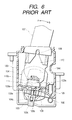
- FIG. 6 is a cross sectional view schematically showing the construction of the turn signal switch device
- FIG. 7 is a front view of a movable member provided in the turn signal switch device
- FIGS. 8A and 8B are schematic diagrams illustrating the operation of a cancel mechanism provided in the turn signal switch device.
- a housing 100 is substantially box-shaped, made of insulating resin, and is secured to a column (not shown), which is a stator member of a steering device, and the like.
- a guide shaft 101 and a support shaft 102 are formed to protrude at a predetermined interval, and at the end of the bottom surface, a cylindrical protrusion 106 is provided.
- a V-shaped cam surface 109 having a pair of lock portions 109 a on the right and left sides.
- a second lever member 104 is made of insulating resin; has an outside shape being substantially rectangular; has a first opening 104 b and a second opening 104 c ; between these two openings, there is provided a shaft hole 104 d ; and at the outer end of the first opening 104 b , a connection pin 104 a is formed.
- a shaft hole 104 d of the second lever member is rotatably fitted in a support shaft 102 provided in the bottom surface of the housing 100 .
- the first lever member 103 is made of insulating resin, is square bar-shaped, and has a first elongated hole 103 a and a second elongated hole 103 b which are arranged in a line in the longitudinal direction. Further, at the front and rear ends of the first lever member 103 in the longitudinal direction, there are provided an abutting portion 103 c and a cam 103 d respectively, the cross sectional configuration of the cam 103 d being semi-circular.
- the first elongated hole 103 a of the first lever member 103 is slidably fitted in the guide shaft 101 formed on the bottom surface of the housing 100
- the second elongated hole 103 b is slidably fitted in a connection pin 104 a provided in the second lever member 104 to connect the first lever member 103 with the second lever member 104 .
- a torsion coil spring 105 wire formed of elastic material is wound several turns, both ends are left in a straight line state, the wound portion is fitted in and fixed to a protrusion 106 of the housing 100 , one of the straight line-shaped portions at both ends is fixed to the end of the bottom surface of the housing 100 , and the other is engaged with the first lever member, whereby the first lever member 103 is adapted to be elastically biased in the direction that goes away from the second lever member 104 in the longitudinal direction of the first lever member 103 .
- a holder 110 is a structure made of insulating resin, is mounted within the housing 100 , has support shafts 108 at both ends, and is provided with a cylinder 110 a protruding,on the front side. Inside the cylinder 110 a , a driving member 111 is slidably held, and the forward end of this driving member 111 is constantly held in press contact with the cam surface 109 of the housing 100 by a spring (not shown).
- An operating lever 107 is made of insulating resin, is substantially cylindrical, the base end is fitted in support shafts 108 at both ends of the holder 110 , and is supported by the housing 100 so as to be rotatable together with the holder 110 in the direction indicated by the arrow a or b.
- a movable member 115 is constructed such that, at the center of a rectangular plate member made of insulating resin, there is integrally provided a cylinder portion 115 a vertically to the plate member; at the top end, there are provided a pair of engagement claws 115 b ; the wound portion of a return spring 116 wound is wound around the cylinder portion 115 a ; and both arms of the return spring 116 are restrained by a pair of engagement claws 115 b and 115 b .
- a cylinder 110 a of the holder 110 is rotatably housed.
- the both arms of the return spring 116 are restrained by a pair of engagement claws 115 b and 115 b and engaged with the holder 110 , whereby the movable member 115 is constantly biased toward a predetermined stable position with respect to the holder 110 . Therefore, normally the rotation of the operating lever 107 rotates integrally the movable member 115 together with the holder 110 .
- the movable member 115 is provided with a cam 112 having a semi-circular cross sectional configuration and a receiving portion 113 , and the cam 112 is opposed to the cam 103 d of the first lever member 103 , the receiving portion 113 protruding in the second opening 104 c of the second lever member 104 .
- the abutting portion 103 c of the first lever member 103 is positioned outside the rotation path of a cancel protrusion 114 rotating with the steering wheel; even if the steering wheel is turned in this state, the cancel protrusion 114 does not abut the abutting portion 103 c of the first lever member 103 , and the operating lever 107 is maintained at the neutral position.
- the cam 112 is detached from the apex of the cam 103 d of the first lever member 103 , and the first lever member 103 receives the elastic force of the torsion coil spring 105 to advance along the longitudinal direction of the both elongated holes 103 a and 103 b , the abutting portion 103 c advancing into the rotation path of the cancel protrusion 114 .
- switching operation is effected on a contact (not shown), and the right-hand turn lamp blinks.
- the periphery of the second opening 104 c upwardly pressurizes the receiving portion 113 of the movable member 115 , so that the driving member 111 is detached from the lock portion 109 a of the cam surface 109 and moves toward the central valley, and the operating lever 107 and the first and second lever members 103 and 104 are automatically restored to the neutral position shown in FIG. 8 A.
- a turn signal switch device comprising: a housing equipped with a cancel protrusion outward which rotates in accordance with a steering wheel operation; a cam surface formed within the housing; first biasing means for applying a biasing force toward the cam surface; a holder rotatably mounted to the housing; an operating lever integrally provided in the holder and provided extending outwardly of the housing; a first cam integrally provided in the holder; a second cam which abuts the first cam in a direction toward a rotation path of the cancel protrusion; a first cancel lever integrally formed in the second cam, which is engaged with and mounted to the housing so as to be displaceable and rotatable until the rotation path of the cancel protrusion is reached; second biasing means which applies a biasing force so as to displace the first cancel lever in accordance with a displacement in an abutted position between the first cam and the second cam toward the rotation path of the cancel protrusion; and a second cancel lever which is rot
- the structure is arranged such that the center of rotation of the second cancel lever is a protrusion shaft or an elongated hole, the protrusion shaft or the elongated hole is inserted into an elongated hole or a protrusion shaft provided in a bottom plate of the housing, and is caught between both ends of a spring mounted to the bottom plate or the second cancel lever in order that the both ends may be exposed in the elongated hole to hold the protrusion shaft at a central position of the elongated hole; the operating lever is caused to be automatically restored from an operating position to the neutral position in interlock with the rotating operation of the first and second cancel levers in such a state; and when an excess load for preventing automatic restoration from the operating position to the neutral position is applied to the operating lever, the protrusion shaft is moved from the central position of the elongated hole to the end position against a resilient force of the spring, whereby the first and second cancel levers are allowed to rotate.
- the structure is arranged such that the center of rotation of the second cancel lever is a rotating shaft, which is a protrusion shaft; the rotating shaft is inserted into an elongated hole provided in the bottom plate of the housing and is caught between both ends of a spring mounted to the bottom plate in order that the both ends are exposed in the elongated hole to hold the rotating shaft at a central position of the elongated hole; the operating lever is caused to be automatically restored from the operating position to the neutral position in interlock with rotating operation of the first and second cancel levers in such a state; and when an excess load for preventing automatic restoration from the operating position to the neutral position is applied to the operating lever, the rotating shaft is moved from the central position of the elongated hole to an end position against the resilient force of the spring, whereby the cancel levers are allowed to rotate.
- the center of rotation of the second cancel lever is a rotating shaft, which is a protrusion shaft
- the rotating shaft is inserted into an elongated hole provided in the bottom plate of the housing and is caught between both
- the spring is provided on a protruded portion on a back surface side of the bottom plate, and between both ends of the spring, a stopper member having the substantially same width as a diameter of the rotating shaft which is provided on the back surface side of the bottom plate and the rotating shaft are caught.
- the spring is a coil spring having straight lines at the both ends respectively, and between the both ends, the rotating shaft and a stopper member having the substantially same width as the diameter of the rotating shaft are caught.
- the stopper member is a wall, and this wall is provided between the elongated hole and the protruded portion integrally with the bottom plate.
- the wall which is a stopper member, is between the elongated hole and protruded portion, it is easy to mount by engaging the spring with the stopper member.
- the first biasing means is a coil spring.
- cam surface is shaped like a letter V.
- the member pressurized easily takes a neutral position because of the shape of the letter V.
- FIG. 1 is an exploded perspective view of a turn signal switch device according to an embodiment of the present invention
- FIG. 2 is a longitudinal sectional view of the turn signal switch device according to the embodiment of the present invention.
- FIG. 3 is a transverse sectional view showing a main portion of the turn signal switch device according to the embodiment of the present invention.
- FIG. 4 is a diagram illustrating the operation of the turn signal switch device according to the embodiment of the present invention.
- FIGS. 5A, 5 B, and 5 C are partial enlarged views showing the turn signal switch device according to the embodiment of the present invention (diagram illustrating the operation);
- FIG. 6 is a transverse sectional view schematically showing the structure of a conventional turn signal switch device
- FIG. 7 is a front view showing a movable member to be provided in the conventional turn signal switch device.
- FIG. 8 is a diagram illustrating the operation of a cancel mechanism to be provided in the conventional turn signal switch device.
- FIG. 1 is an exploded perspective view of a turn signal switch device according to an embodiment of the present invention
- FIG. 2 is a longitudinal sectional view of the turn signal switch device according to the embodiment of the present invention
- FIG. 3 is a transverse sectional view showing a main portion of the turn signal switch device according to the embodiment of the present invention
- FIG. 4 is a diagram illustrating the operation of the turn signal switch device according to the embodiment of the present invention
- FIG. 5 is a partial enlarged view showing the turn signal switch device according to the embodiment of the present invention (diagram illustrating the operation).
- a housing 1 is formed of a first case 2 and a second case 3 which are made of insulating resin, and both cases 2 and 3 are fitted in to constitute the housing 1 .
- the first case 2 has a V-shaped cam surface 2 b having a pair of protruded portions 2 c and 2 c on the right and left sides inside, and has a shaft hole 2 a at the end of the wall surface.
- the second case 3 has, on the surface side of the bottom plate 3 a , an elongated hole 3 b , two rectangular operating holes 3 c and 3 d , a shaft hole 3 e , a protrusion 3 j and a guide shaft 3 f , and on the back surface side of the bottom plate 3 a , there is formed a pin 3 h , which is a cylindrical protruded portion, and between the pin 3 h and the elongated hole 3 b , there is projectingly formed a wall-shaped stopper member 3 i.
- the second cancel lever 4 is a plate member made of insulating resin, has an outside shape being substantially rectangular, and has a first opening 4 c and a second opening 4 d having a periphery 4 e ; on the back surface side between two openings 4 c and 4 d , there is provided a protrusion shaft 4 a ; and on the surface side at the outside end of the first opening 4 c , there is formed a connection pin 4 b .
- the protrusion shaft 4 a of the second cancel lever 4 is slidably and rotatably inserted into the elongated hole 3 b of the second case 3 as a rotating shaft.
- the first cancel lever 5 is made of insulating resin, is square bar-shaped, and has a first elongated hole 5 a and a second elongated hole 5 b which are arranged in a line in the longitudinal direction. Further, at the front and rear ends of the first cancel lever 5 in the longitudinal direction, there are provided an abutting portion 5 c and a second cam 5 d respectively, the cross sectional configuration of the second cam 5 d being semi-circular. On the first cancel lever 5 is formed a rod-shaped protrusion 5 e in opposite to the first elongated hole 5 a .
- the first elongated hole 5 a of the first cancel lever 5 is slidably fitted in the guide shaft 3 f formed on the surface side of the bottom plate 3 a of the second case 3 of the housing 1 within the first opening 4 c of the second cancel lever 4 , and the second elongated hole 5 b is inserted into a connection pin 4 b provided at the outside end of the second cancel lever 4 to connect the first cancel lever 5 with the second cancel lever 4 .
- a spring 6 is constructed such that wire made of elastic material is wound like a coil, and its both ends are drawn out from the wound portion 6 a in equal length in a straight line shape in parallel to provide two straight lines 6 b and 6 b .
- the wound portion 6 a of the spring 6 is fitted in and fixed to a pin 3 h of the bottom plate 3 a on the back surface side; a distance between the both straight lines 6 b and 6 b , the length of a wall-shaped stopper member 3 i protruding on the back surface side of the bottom plate 3 a in the longitudinal direction, and the diameter of the pin 3 h are set to the substantially same size; and the both straight lines 6 b and 6 b are held in the central portion of the elongated hole 3 b provided in the bottom plate 3 a in a bridge-constructed state.
- the protrusion shaft 4 a of the second cancel lever 4 whose diameter is a slightly larger size than the distance between the both straight lines 6 b and 6 b is inserted so that the protrusion shaft 4 a is elastically held at the central position of the elongated hole 3 b by the both straight lines 6 b and 6 b .
- Second biasing means 13 has a short side 13 b and a long side 13 c obtained by winding wire made of elastic material like a coil to draw out its both ends from the wound portion 13 a in a straight-line shape.
- the wound portion 13 a is fixed to a protrusion 3 j of the second case 3
- the short side 13 b is engaged with and fixed to the side wall of the second case 3 .
- the long side 13 c is engaged with a protrusion 5 e of the first cancel lever 5 to bias the first cancel lever 5 in the longitudinal direction of the first cancel lever 5 so as to go away from the second cancel lever 4 .
- a holder 7 is a structure made of insulating resin, has a pressurizing member 7 c and a first spring 7 d , and, at its both ends, has support shafts 7 a and 7 a , and support shafts 7 e and 7 e to be opposed to each other in a direction perpendicular to the support shafts 7 a and 7 a ; a cylinder 7 b is formed to protrude on the front surface; and at the forward end of the cylinder 7 b , a first cam 7 g having a convex lens-cross sectional configuration protrudes in the perpendicular direction. Also, in the central portion of the holder 7 , there is provided a protrusion 7 f .
- the holder 7 is mounted within the housing 1 ; within the cylinder 7 b , the pressurizing member 7 c is slidably held; and the forward end of this pressurizing member 7 c is constantly held in press contact with the cam surface 2 b of the first case 2 of the housing 1 by a long and narrow coil-shaped first spring 7 d inserted into the pressurizing member 7 c .
- the support shafts 7 a and 7 a are fitted in shaft holes 2 a and 3 e provided in the first case 2 and the second case 3 of the housing 1 respectively to rotatably support the holder 7 with respect to the housing 1 .
- first cam 7 g having a convex lens-cross sectional configuration is engaged with the second cam 5 d of the first cancel lever 5 so that the protrusion 7 f is adapted to be positioned in the second opening 4 d of the second cancel lever 4 .
- An operating member 8 is long and narrow rod-shaped made of insulating resin; has a pressurizing member 8 c and the first spring 8 d ; at the forward end, there is provided a cylindrical hole 8 a ; and at the central side portion, there is provided a protrusion 8 e .
- the pressurizing member 8 c is slidably held; the forward end of this pressurizing member 8 c is constantly held in press contact with a cam surface (not shown) provided on the holder 7 by long and narrow coil-shaped first biasing means 8 d inserted into the pressurizing member 8 c .
- the operating member 8 is provided with shaft holes 8 b and 8 b ; the shaft holes 8 b and 8 b are fitted in the support shafts 7 e and 7 e of the holder 7 ; the operating member 8 is supported to be rotatable with respect to the holder 7 ; and the holder 7 enables to rotate in a plane substantially perpendicular to the plane which rotates with respect to the housing 1 .
- An operating lever 9 is made of insulating resin, is substantially cylindrical, and a base end thereof is firmly fitted in and fixed to the rear end of the operating member 8 .
- the operating lever 9 is rotatably supported in two planes which are substantially perpendicular to each other through the operating member 8 .
- Contact switching members 10 , 11 are composed of: operating portions 10 a , 11 a ; bodies 10 b , 11 b ; and movable contacts 10 c , 11 c , and the movable contacts 10 c , 11 c are attached to the bodies 10 b , 11 b respectively such that the operating portions 11 a , 11 a are driven to move the movable contact.
- the operating portion 10 a is engaged with a protrusion wall (not shown) of the holder 7 through an operating hole 3 c of the housing 1 to be driven by the rotation of the holder 7 .
- the operating portion 11 a is engaged with the protrusion 8 e of the operating member 8 through the operating hole 3 c of the housing 1 to be driven by the rotation of the operating member 8 with respect to the holder 7 .
- a printed substrate 12 has switching contacts 12 a and 12 b , and has, on the back surface, a connector 12 c which is electrically connected through the switching contacts and wiring.
- the switching contacts 12 a , 12 b are slidably contacted by the movable contacts 10 c , 11 c of the contact switching members 10 , 11 in such a manner as to send an ON/OFF signal depending upon movement of the movable contacts 10 c , 11 c.
- the abutting portion 5 c of the first cancel lever 5 is positioned outside the rotation path of the cancel protrusion 14 rotating with the steering wheel. Even if the steering wheel is turned in this state, the cancel protrusion 14 does not abut the abutting portion 5 c of the first cancel lever 5 , and the operating lever 9 is maintained at the neutral position.
- this first cam 7 g is detached from the apex of the second cam 5 d of the first cancel lever 5 , the first cancel lever 5 receives the elastic force of the second biasing means 13 to advance along the longitudinal direction of both elongated holes 5 a and 5 b , and the abutting portion 5 c comes into the rotation path of the cancel protrusion 14 .
- the holder 7 rotates clockwise around its support shaft 7 a , and the pressurizing member 7 c displaces downward on the cam surface 2 b to go over a protruded portion 2 c formed on the cam surface 2 b and is stably held. Further, with the rotation of the operating lever 9 in the direction of the arrow B, the operation of the contact switching member 10 is performed to blink a right-turn lamp (not shown).
- the protrusion shaft 4 a is retained in the vicinity of the center of the elongated hole 3 b by the spring 6 , and even if the periphery 4 e of the second opening 4 d pressurizes the protrusion 7 f of the holder 7 upwardly, the protrusion shaft 4 a is held by the elastic force of the spring 6 in such a manner that the position of the protrusion shaft 4 a does not move from the vicinity of the center of the elongated hole 3 b.
- the protrusion shaft 4 a of the second cancel lever 4 moves from the stable position to the retracted position against the biasing force of one straight line 6 b of the spring 6 .
- the cancel protrusion 14 passes the abutting portion 5 c of the first cancel lever 5 , the protrusion shaft 4 a is automatically restored from the retracted position to the stable position by the biasing force of the spring 6 , so that it is maintained in the right-hand turn state shown in FIGS. 4B and 5B again.
- the second cancel lever 4 has been provided with the protrusion shaft 4 a
- the bottom plate 3 a has been provided with the elongated hole 3 b
- the spring 6 has been mounted to the bottom plate 3 a
- the present invention is not limited thereto. It is possible to provide the second cancel lever 4 with an elongated hole, to provide the bottom plate with a protrusion shaft, and to mount a spring to the second cancel lever 4 .
- the protruded portion 3 h and the stopper member 3 i have been provided on the back surface side of the bottom plate 3 a , but the present invention is not limited thereto.
- the protruded portion and stopper member may be provided on the surface side of the bottom plate.
- a turn signal switch device comprising: a housing equipped with a cancel protrusion outward which rotates in accordance with a steering wheel operation; a cam surface formed within the housing; first biasing means for applying a biasing force toward the cam surface; a holder rotatably mounted to the housing; an operating lever integrally provided in the holder, and provided extending outwardly of the housing; a first cam integrally provided in the holder; a second cam which abuts the first cam in a direction toward the rotation path of the cancel protrusion; a first cancel lever integrally formed in the second cam, which is engaged with and is mounted to the housing so as to be displaceable and rotatable until the rotation path of the cancel protrusion is reached; second biasing means which applies a biasing force so as to displace the first cancel lever in accordance with a displacement in an abutted position between the first cam and the second cam toward the rotation path of the cancel protrusion; and a second cancel
Landscapes
- Engineering & Computer Science (AREA)
- Mechanical Engineering (AREA)
- Lighting Device Outwards From Vehicle And Optical Signal (AREA)
- Switches With Compound Operations (AREA)
- Mechanisms For Operating Contacts (AREA)
Abstract
The turn signal switch device is provided with: a housing; an operating lever rotatably supported by the housing; a first cancel lever which is rotated by abutting a cancel protrusion on a steering wheel side; and a second cancel lever rotatable in interlock with the first cancel lever, wherein a protrusion shaft or an elongated hole of the second cancel lever is inserted in an elongated hole or the protrusion shaft provided in a bottom plate of the housing, and wherein in order that both ends may be exposed in the elongated hole, the protrusion shaft is caught between both ends of the second spring mounted to the bottom plate or the second cancel lever to be held at a central position of the elongated hole.
Description
1. Field of the Invention
The present invention relates to a turn signal switch device attached to a steering column or the like of an automobile and serving as a direction indicator and, more specifically, it relates to a mechanism for releasing an excess load when, in a cancel operation for automatically restoring an operating lever provided in the turn signal switch device from an operating position to a neutral position, an external force preventing the automatic restoring is applied to the operating lever.
2. Description of Related Art
In the turn signal switch device of an automobile, the base end of an operating lever is rotatably supported by a housing integrally formed with the steering column or the like, and the forward end of this operating lever is rotated from a neutral position to a right or left direction indicating position, whereby a right-turn or left-turn lamp is caused to blink. In such a turn signal switch device, to retain the operating lever at three positions of the right and left direction indicating positions and the neutral position, the inner surface of the housing is provided with a cam surface, and the operating lever is provided, through the intermediation of a spring, with a pressurizing member to be engaged with the cam surface. Further, there is provided a cancel mechanism for automatically restoring the operating lever to the neutral position when the steering wheel is turned in a returning direction which is a direction opposite to the indicated direction, with the operating lever rotated to the right or left direction indicating position.
The description will be made of drawings showing such a cancel mechanism according to the prior art. FIG. 6 is a cross sectional view schematically showing the construction of the turn signal switch device; FIG. 7 is a front view of a movable member provided in the turn signal switch device; and FIGS. 8A and 8B are schematic diagrams illustrating the operation of a cancel mechanism provided in the turn signal switch device.
With reference to FIGS. 6 to 8, the description will be made of the turn signal switch device according to the prior art. A housing 100 is substantially box-shaped, made of insulating resin, and is secured to a column (not shown), which is a stator member of a steering device, and the like. On the bottom surface of the housing 100, a guide shaft 101 and a support shaft 102 are formed to protrude at a predetermined interval, and at the end of the bottom surface, a cylindrical protrusion 106 is provided. Also, inside the housing 100, there is formed a V-shaped cam surface 109 having a pair of lock portions 109 a on the right and left sides.
A second lever member 104 is made of insulating resin; has an outside shape being substantially rectangular; has a first opening 104 b and a second opening 104 c; between these two openings, there is provided a shaft hole 104 d; and at the outer end of the first opening 104 b, a connection pin 104 a is formed. A shaft hole 104 d of the second lever member is rotatably fitted in a support shaft 102 provided in the bottom surface of the housing 100.
The first lever member 103 is made of insulating resin, is square bar-shaped, and has a first elongated hole 103 a and a second elongated hole 103 b which are arranged in a line in the longitudinal direction. Further, at the front and rear ends of the first lever member 103 in the longitudinal direction, there are provided an abutting portion 103 c and a cam 103 d respectively, the cross sectional configuration of the cam 103 d being semi-circular. The first elongated hole 103 a of the first lever member 103 is slidably fitted in the guide shaft 101 formed on the bottom surface of the housing 100, and the second elongated hole 103 b is slidably fitted in a connection pin 104 a provided in the second lever member 104 to connect the first lever member 103 with the second lever member 104.
In a torsion coil spring 105, wire formed of elastic material is wound several turns, both ends are left in a straight line state, the wound portion is fitted in and fixed to a protrusion 106 of the housing 100, one of the straight line-shaped portions at both ends is fixed to the end of the bottom surface of the housing 100, and the other is engaged with the first lever member, whereby the first lever member 103 is adapted to be elastically biased in the direction that goes away from the second lever member 104 in the longitudinal direction of the first lever member 103.
A holder 110 is a structure made of insulating resin, is mounted within the housing 100, has support shafts 108 at both ends, and is provided with a cylinder 110 a protruding,on the front side. Inside the cylinder 110 a, a driving member 111 is slidably held, and the forward end of this driving member 111 is constantly held in press contact with the cam surface 109 of the housing 100 by a spring (not shown).
An operating lever 107 is made of insulating resin, is substantially cylindrical, the base end is fitted in support shafts 108 at both ends of the holder 110, and is supported by the housing 100 so as to be rotatable together with the holder 110 in the direction indicated by the arrow a or b.
A movable member 115 is constructed such that, at the center of a rectangular plate member made of insulating resin, there is integrally provided a cylinder portion 115 a vertically to the plate member; at the top end, there are provided a pair of engagement claws 115 b; the wound portion of a return spring 116 wound is wound around the cylinder portion 115 a; and both arms of the return spring 116 are restrained by a pair of engagement claws 115 b and 115 b. Inside the cylinder portion 115 a, a cylinder 110 a of the holder 110 is rotatably housed. The both arms of the return spring 116 are restrained by a pair of engagement claws 115 b and 115 b and engaged with the holder 110, whereby the movable member 115 is constantly biased toward a predetermined stable position with respect to the holder 110. Therefore, normally the rotation of the operating lever 107 rotates integrally the movable member 115 together with the holder 110. Further, the movable member 115 is provided with a cam 112 having a semi-circular cross sectional configuration and a receiving portion 113, and the cam 112 is opposed to the cam 103 d of the first lever member 103, the receiving portion 113 protruding in the second opening 104 c of the second lever member 104.
Next, the description will be made of an operation of the turn signal switch device, constructed as described above. When the operating lever 107 is at the neutral position, the forward end of the driving member 111 abuts the central valley of the cam surface 109, and is stably held at the position by the elasticity of a spring (not shown). At this time, as shown in FIG. 8A, the cam 112 of the movable member 115 on the operating lever 107 side and the cam 103 d of the first lever member 103 are in contact with each other at their apexes, and the first lever member 103 retracts against the biasing force of the torsion coil spring 105. Thus, the abutting portion 103 c of the first lever member 103 is positioned outside the rotation path of a cancel protrusion 114 rotating with the steering wheel; even if the steering wheel is turned in this state, the cancel protrusion 114 does not abut the abutting portion 103 c of the first lever member 103, and the operating lever 107 is maintained at the neutral position.
When the operating lever 107 is rotated from this neutral position in the direction of the arrow a or the arrow b in FIG. 6, the forward end of the driving member 111 moves over the slope of the cam surface 109 and is engaged with the lock portion 109 a, and stably held at the position by the lock portion 109 a. For example, when the operating lever 107 is rotated in the direction of the arrow b in FIG. 6, the movable member 115 integrally rotates in interlock with that, and the cam 112 and the receiving portion 113 of the movable member 115 are displaced from the position shown in FIG. 8A to that shown in FIG. 8B. As a result, the cam 112 is detached from the apex of the cam 103 d of the first lever member 103, and the first lever member 103 receives the elastic force of the torsion coil spring 105 to advance along the longitudinal direction of the both elongated holes 103 a and 103 b, the abutting portion 103 c advancing into the rotation path of the cancel protrusion 114. Further, with the rotation of the operating lever 107 in the direction of the arrow b, switching operation is effected on a contact (not shown), and the right-hand turn lamp blinks.
When the steering wheel is turned in the opposite direction (the direction of the arrow in the drawing) in the right-hand turn state shown in FIG. 8B, the cancel protrusion 114 abuts the abutting portion 103 c of the first lever member 103 during the return operation. As a result, the first lever member 103 rotates clockwise as seen in the drawing around the guide shaft 101, and the torque is transmitted from the second elongated hole 103 b to a second lever member 104 through a connection pin 104 a, and the second lever member 104 rotates clockwise around the support shaft 102, so that the second opening 104 c of the second lever member 104 is rotated and displaced upward as seen in the drawing. As a result, the periphery of the second opening 104 c upwardly pressurizes the receiving portion 113 of the movable member 115, so that the driving member 111 is detached from the lock portion 109 a of the cam surface 109 and moves toward the central valley, and the operating lever 107 and the first and second lever members 103 and 104 are automatically restored to the neutral position shown in FIG. 8A.
At this time, when some force preventing the automatic restoration is applied to the operating lever 107 in the right-hand turn state shown in FIG. 8B, for example, when the steering wheel is turned in the opposite direction with the operating lever 107 being pressed by the driver, the periphery of the second opening 104 c upwardly pressurizes the receiving portion 113 of the movable member 115 as described above. However, the operating lever 107, which is being pressed, is not automatically restored. In this case, the movable member 115 rotates the peripheral surface of the cylinder 110 a of the holder 110 from the stable position to the retracted position against the biasing force of the return spring 116. And, when the cancel protrusion 114 passes the abutting portion 103 c of the first lever member 103, the movable member 115 is automatically restored from the retracted position to the stable position by the biasing force of the return spring 116, so that it is maintained in the right-hand turn state shown in FIG. 8B again.
In the above-described conventional turn signal switch device, when some force preventing automatic restoration is applied to the operating lever 107 when automatically restoring the operating lever 107 from the operating position to the neutral position, an excess load generated between the second opening 104 c of the second lever member 104 and the receiving portion 113 of the movable member 115 is released (absorbed) by the rotation of the movable member 115, so that it is possible to prevent breakage of the power transmission system including the first and second lever members 103 and 104 and the receiving portion 113. However, to install such a mechanism, it is necessary to provide the rotatable movable member 115 and the return spring 116 which elastically biases the movable member 115 toward the stable position, and the number of parts increases due to the movable member 115 and the return spring 116. Further, due to the mounting space for the movable member 115 and the return spring 116, the size of the turn signal switch device is enlarged.
Therefore, it is an object of the present invention to provide a small-sized turn signal switch device easy to assemble by reducing the number of parts.
In accordance with the present invention, there is provided a turn signal switch device comprising: a housing equipped with a cancel protrusion outward which rotates in accordance with a steering wheel operation; a cam surface formed within the housing; first biasing means for applying a biasing force toward the cam surface; a holder rotatably mounted to the housing; an operating lever integrally provided in the holder and provided extending outwardly of the housing; a first cam integrally provided in the holder; a second cam which abuts the first cam in a direction toward a rotation path of the cancel protrusion; a first cancel lever integrally formed in the second cam, which is engaged with and mounted to the housing so as to be displaceable and rotatable until the rotation path of the cancel protrusion is reached; second biasing means which applies a biasing force so as to displace the first cancel lever in accordance with a displacement in an abutted position between the first cam and the second cam toward the rotation path of the cancel protrusion; and a second cancel lever which is rotatably engaged with each of the first cancel lever and the housing so as to rotate in the same direction as the direction of rotation of the first cancel lever in interlock with the rotation of the first cancel lever, wherein the second cancel lever is engaged with and mounted to the holder in such a manner that a direction of rotation of the second cancel lever is opposite to that of the holder, and wherein a center of rotation of the second cancel lever with respect to the housing is made displaceable within a predetermined range from a neutral position and the center of rotation displaced is made automatically restorable to the neutral position.
According to this structure, it is possible to provide a small-sized turn signal switch device which is capable of reducing the number of parts and easy to assemble.
Also, the structure is arranged such that the center of rotation of the second cancel lever is a protrusion shaft or an elongated hole, the protrusion shaft or the elongated hole is inserted into an elongated hole or a protrusion shaft provided in a bottom plate of the housing, and is caught between both ends of a spring mounted to the bottom plate or the second cancel lever in order that the both ends may be exposed in the elongated hole to hold the protrusion shaft at a central position of the elongated hole; the operating lever is caused to be automatically restored from an operating position to the neutral position in interlock with the rotating operation of the first and second cancel levers in such a state; and when an excess load for preventing automatic restoration from the operating position to the neutral position is applied to the operating lever, the protrusion shaft is moved from the central position of the elongated hole to the end position against a resilient force of the spring, whereby the first and second cancel levers are allowed to rotate.
According to this structure, it is possible to reduce the number of parts and to provide a small-sized turn signal switch device easy to assemble.
Also, the structure is arranged such that the center of rotation of the second cancel lever is a rotating shaft, which is a protrusion shaft; the rotating shaft is inserted into an elongated hole provided in the bottom plate of the housing and is caught between both ends of a spring mounted to the bottom plate in order that the both ends are exposed in the elongated hole to hold the rotating shaft at a central position of the elongated hole; the operating lever is caused to be automatically restored from the operating position to the neutral position in interlock with rotating operation of the first and second cancel levers in such a state; and when an excess load for preventing automatic restoration from the operating position to the neutral position is applied to the operating lever, the rotating shaft is moved from the central position of the elongated hole to an end position against the resilient force of the spring, whereby the cancel levers are allowed to rotate.
According to this structure, it is possible to reduce the number of parts, and to provide a small-sized turn signal switch device easy to assemble.
Also, the spring is provided on a protruded portion on a back surface side of the bottom plate, and between both ends of the spring, a stopper member having the substantially same width as a diameter of the rotating shaft which is provided on the back surface side of the bottom plate and the rotating shaft are caught.
According to this structure, since the back surface side of the bottom plate is used, it is easy to secure space for forming the protruded portion and the stopper member.
Also, the spring is a coil spring having straight lines at the both ends respectively, and between the both ends, the rotating shaft and a stopper member having the substantially same width as the diameter of the rotating shaft are caught.
According to this structure, since a general coil spring is used, it is easy to handle.
Also, the stopper member is a wall, and this wall is provided between the elongated hole and the protruded portion integrally with the bottom plate.
According to this structure, since the wall, which is a stopper member, is between the elongated hole and protruded portion, it is easy to mount by engaging the spring with the stopper member.
Also, the first biasing means is a coil spring.
According to this structure, since a general coil spring is used, it is easy to handle.
Also, the cam surface is shaped like a letter V.
According to this structure, the member pressurized easily takes a neutral position because of the shape of the letter V.
FIG. 1 is an exploded perspective view of a turn signal switch device according to an embodiment of the present invention;
FIG. 2 is a longitudinal sectional view of the turn signal switch device according to the embodiment of the present invention;
FIG. 3 is a transverse sectional view showing a main portion of the turn signal switch device according to the embodiment of the present invention;
FIG. 4 is a diagram illustrating the operation of the turn signal switch device according to the embodiment of the present invention;
FIGS. 5A, 5B, and 5C are partial enlarged views showing the turn signal switch device according to the embodiment of the present invention (diagram illustrating the operation);
FIG. 6 is a transverse sectional view schematically showing the structure of a conventional turn signal switch device;
FIG. 7 is a front view showing a movable member to be provided in the conventional turn signal switch device; and
FIG. 8 is a diagram illustrating the operation of a cancel mechanism to be provided in the conventional turn signal switch device.
The description will be made of the drawings of the turn signal switch device according to the present invention. FIG. 1 is an exploded perspective view of a turn signal switch device according to an embodiment of the present invention, FIG. 2 is a longitudinal sectional view of the turn signal switch device according to the embodiment of the present invention, FIG. 3 is a transverse sectional view showing a main portion of the turn signal switch device according to the embodiment of the present invention, FIG. 4 is a diagram illustrating the operation of the turn signal switch device according to the embodiment of the present invention, and FIG. 5 is a partial enlarged view showing the turn signal switch device according to the embodiment of the present invention (diagram illustrating the operation).
Next, with reference to FIGS. 1 to 5, the description will be made of embodiments of the present invention. A housing 1 is formed of a first case 2 and a second case 3 which are made of insulating resin, and both cases 2 and 3 are fitted in to constitute the housing 1. The first case 2 has a V-shaped cam surface 2 b having a pair of protruded portions 2 c and 2 c on the right and left sides inside, and has a shaft hole 2 a at the end of the wall surface. The second case 3 has, on the surface side of the bottom plate 3 a, an elongated hole 3 b, two rectangular operating holes 3 c and 3 d, a shaft hole 3 e, a protrusion 3 j and a guide shaft 3 f, and on the back surface side of the bottom plate 3 a, there is formed a pin 3 h, which is a cylindrical protruded portion, and between the pin 3 h and the elongated hole 3 b, there is projectingly formed a wall-shaped stopper member 3 i.
The second cancel lever 4 is a plate member made of insulating resin, has an outside shape being substantially rectangular, and has a first opening 4 c and a second opening 4 d having a periphery 4 e; on the back surface side between two openings 4 c and 4 d, there is provided a protrusion shaft 4 a; and on the surface side at the outside end of the first opening 4 c, there is formed a connection pin 4 b. The protrusion shaft 4 a of the second cancel lever 4 is slidably and rotatably inserted into the elongated hole 3 b of the second case 3 as a rotating shaft.
The first cancel lever 5 is made of insulating resin, is square bar-shaped, and has a first elongated hole 5 a and a second elongated hole 5 b which are arranged in a line in the longitudinal direction. Further, at the front and rear ends of the first cancel lever 5 in the longitudinal direction, there are provided an abutting portion 5 c and a second cam 5 d respectively, the cross sectional configuration of the second cam 5 d being semi-circular. On the first cancel lever 5 is formed a rod-shaped protrusion 5 e in opposite to the first elongated hole 5 a. The first elongated hole 5 a of the first cancel lever 5 is slidably fitted in the guide shaft 3 f formed on the surface side of the bottom plate 3 a of the second case 3 of the housing 1 within the first opening 4 c of the second cancel lever 4, and the second elongated hole 5 b is inserted into a connection pin 4 b provided at the outside end of the second cancel lever 4 to connect the first cancel lever 5 with the second cancel lever 4.
A spring 6 is constructed such that wire made of elastic material is wound like a coil, and its both ends are drawn out from the wound portion 6 a in equal length in a straight line shape in parallel to provide two straight lines 6 b and 6 b. The wound portion 6 a of the spring 6 is fitted in and fixed to a pin 3 h of the bottom plate 3 a on the back surface side; a distance between the both straight lines 6 b and 6 b, the length of a wall-shaped stopper member 3 i protruding on the back surface side of the bottom plate 3 a in the longitudinal direction, and the diameter of the pin 3 h are set to the substantially same size; and the both straight lines 6 b and 6 b are held in the central portion of the elongated hole 3 b provided in the bottom plate 3 a in a bridge-constructed state. Inside the elongated hole 3 b, between the both straight lines 6 b and 6 b, the protrusion shaft 4 a of the second cancel lever 4 whose diameter is a slightly larger size than the distance between the both straight lines 6 b and 6 b is inserted so that the protrusion shaft 4 a is elastically held at the central position of the elongated hole 3 b by the both straight lines 6 b and 6 b.
Second biasing means 13 has a short side 13 b and a long side 13 c obtained by winding wire made of elastic material like a coil to draw out its both ends from the wound portion 13 a in a straight-line shape. The wound portion 13 a is fixed to a protrusion 3 j of the second case 3, and the short side 13 b is engaged with and fixed to the side wall of the second case 3. The long side 13 c is engaged with a protrusion 5 e of the first cancel lever 5 to bias the first cancel lever 5 in the longitudinal direction of the first cancel lever 5 so as to go away from the second cancel lever 4.
A holder 7 is a structure made of insulating resin, has a pressurizing member 7 c and a first spring 7 d, and, at its both ends, has support shafts 7 a and 7 a, and support shafts 7 e and 7 e to be opposed to each other in a direction perpendicular to the support shafts 7 a and 7 a; a cylinder 7 b is formed to protrude on the front surface; and at the forward end of the cylinder 7 b, a first cam 7 g having a convex lens-cross sectional configuration protrudes in the perpendicular direction. Also, in the central portion of the holder 7, there is provided a protrusion 7 f. The holder 7 is mounted within the housing 1; within the cylinder 7 b, the pressurizing member 7 c is slidably held; and the forward end of this pressurizing member 7 c is constantly held in press contact with the cam surface 2 b of the first case 2 of the housing 1 by a long and narrow coil-shaped first spring 7 d inserted into the pressurizing member 7 c. The support shafts 7 a and 7 a are fitted in shaft holes 2 a and 3 e provided in the first case 2 and the second case 3 of the housing 1 respectively to rotatably support the holder 7 with respect to the housing 1. Also, the first cam 7 g having a convex lens-cross sectional configuration is engaged with the second cam 5 d of the first cancel lever 5 so that the protrusion 7 f is adapted to be positioned in the second opening 4 d of the second cancel lever 4.
An operating member 8 is long and narrow rod-shaped made of insulating resin; has a pressurizing member 8 c and the first spring 8 d; at the forward end, there is provided a cylindrical hole 8 a; and at the central side portion, there is provided a protrusion 8 e. Inside the cylindrical hole 8 a, the pressurizing member 8 c is slidably held; the forward end of this pressurizing member 8 c is constantly held in press contact with a cam surface (not shown) provided on the holder 7 by long and narrow coil-shaped first biasing means 8 d inserted into the pressurizing member 8 c. Also, the operating member 8 is provided with shaft holes 8 b and 8 b; the shaft holes 8 b and 8 b are fitted in the support shafts 7 e and 7 e of the holder 7; the operating member 8 is supported to be rotatable with respect to the holder 7; and the holder 7 enables to rotate in a plane substantially perpendicular to the plane which rotates with respect to the housing 1.
An operating lever 9 is made of insulating resin, is substantially cylindrical, and a base end thereof is firmly fitted in and fixed to the rear end of the operating member 8. The operating lever 9 is rotatably supported in two planes which are substantially perpendicular to each other through the operating member 8.
Contact switching members 10, 11 are composed of: operating portions 10 a, 11 a; bodies 10 b, 11 b; and movable contacts 10 c, 11 c, and the movable contacts 10 c, 11 c are attached to the bodies 10 b, 11 b respectively such that the operating portions 11 a, 11 a are driven to move the movable contact. The operating portion 10 a is engaged with a protrusion wall (not shown) of the holder 7 through an operating hole 3 c of the housing 1 to be driven by the rotation of the holder 7. The operating portion 11 a is engaged with the protrusion 8 e of the operating member 8 through the operating hole 3 c of the housing 1 to be driven by the rotation of the operating member 8 with respect to the holder 7.
A printed substrate 12 has switching contacts 12 a and 12 b, and has, on the back surface, a connector 12 c which is electrically connected through the switching contacts and wiring. The switching contacts 12 a, 12 b are slidably contacted by the movable contacts 10 c, 11 c of the contact switching members 10, 11 in such a manner as to send an ON/OFF signal depending upon movement of the movable contacts 10 c, 11 c.
Next, the description will be made of an operation of the turn signal switch device constructed as described above. When the operating lever 9 is at the neutral position, the forward end of the pressurizing member 7 c abuts a valley at the center of the cam surface 2 b, and is stably held at the position by the elasticity of the first biasing means 7 d. At this time, as shown in FIG. 4A, the first cam 7 g on the operating lever 9 side and the second cam 5 d of the first cancel lever 5 are in contact with each other at their apexes, and the first cancel lever 5 is retracted against the biasing force of the second biasing means 13. Thus, the abutting portion 5 c of the first cancel lever 5 is positioned outside the rotation path of the cancel protrusion 14 rotating with the steering wheel. Even if the steering wheel is turned in this state, the cancel protrusion 14 does not abut the abutting portion 5 c of the first cancel lever 5, and the operating lever 9 is maintained at the neutral position.
When the operating lever 9 is rotated from this neutral position in the direction of the arrow A or B in FIG. 2, the forward end of the pressurizing member 7 c goes over the slope of the cam surface 2 b to be engaged with a protruded portion 2 c, and is stably held at the position by the protruded portion 2 c. When, for example, the operating lever 9 is rotated in the direction of the arrow B in FIG. 2, the holder 7 integrally rotates in interlock therewith, and the first cam 7 g of the holder 7 and the protrusion 7 f displace from a position indicated in FIG. 4A to a position indicated in FIG. 4B. As a result, this first cam 7 g is detached from the apex of the second cam 5 d of the first cancel lever 5, the first cancel lever 5 receives the elastic force of the second biasing means 13 to advance along the longitudinal direction of both elongated holes 5 a and 5 b, and the abutting portion 5 c comes into the rotation path of the cancel protrusion 14. Thus, the holder 7 rotates clockwise around its support shaft 7 a, and the pressurizing member 7 c displaces downward on the cam surface 2 b to go over a protruded portion 2 c formed on the cam surface 2 b and is stably held. Further, with the rotation of the operating lever 9 in the direction of the arrow B, the operation of the contact switching member 10 is performed to blink a right-turn lamp (not shown).
When in the right-hand turn state shown in FIG. 4A, the steering wheel is turned in the opposite direction (in the direction of the arrow in the drawing), the cancel protrusion 14 abuts the abutting portion 5 c of the first cancel lever 5 during its return operation. As a result, the first cancel lever 5 rotates clockwise as seen in the drawing around the guide shaft 3 f, its torque is transmitted from the second elongated hole 5 b to the second cancel lever 4 through a connection pin 4 b, and this second cancel lever 4 rotates clockwise around the protrusion shaft 4 a. Therefore, the second opening 4 d of the second cancel lever 4 is upwardly rotated and displaced in the drawing. Thereby, since the periphery 4 e of the second opening 4 d pressurizes the protrusion 7 f of the holder 7 upwardly, the holder 7 rotates counterclockwise around its support shaft 7 a, whereby the pressurizing member 7 c is detached from the protruded portion 2 c of the cam surface 2 b to move to the valley at the center so that the operating lever 9 and the first and second cancel levers 5 and 4 are automatically restored to the neutral position shown in FIG. 4A. As shown in FIG. 5B, the protrusion shaft 4 a is retained in the vicinity of the center of the elongated hole 3 b by the spring 6, and even if the periphery 4 e of the second opening 4 d pressurizes the protrusion 7 f of the holder 7 upwardly, the protrusion shaft 4 a is held by the elastic force of the spring 6 in such a manner that the position of the protrusion shaft 4 a does not move from the vicinity of the center of the elongated hole 3 b.
When at this time in the right-hand turn state shown in FIG. 4B some force preventing automatic restoration is applied to the operating lever 9, for example, when the steering wheel is turned in the opposite direction with the operating lever 9 being pressed by the driver, the periphery 4 e of the second opening 4 d pressurizes the protrusion 7 f of the holder 7 upwardly as described above. However, since the operating lever 9, which is being pressed, does not move even if the protrusion 7 f is pressurized, the operating lever is not automatically restored. In this case, as shown in FIGS. 4C and 5C, the protrusion shaft 4 a of the second cancel lever 4 moves from the stable position to the retracted position against the biasing force of one straight line 6 b of the spring 6. And, when the cancel protrusion 14 passes the abutting portion 5 c of the first cancel lever 5, the protrusion shaft 4 a is automatically restored from the retracted position to the stable position by the biasing force of the spring 6, so that it is maintained in the right-hand turn state shown in FIGS. 4B and 5B again.
When the operating lever is turned in the direction of the arrow A in FIG. 2 as shown in FIG. 5A, a left-hand turn state is brought about, and when in this case some force preventing the automatic restoration is applied to the operating lever 9, the protrusion shaft 4 a upwardly bends one straight line 6 b of the spring 6 to move to the retracted position.
In this respect, in the above-described embodiment, the second cancel lever 4 has been provided with the protrusion shaft 4 a, the bottom plate 3 a has been provided with the elongated hole 3 b, and the spring 6 has been mounted to the bottom plate 3 a, but the present invention is not limited thereto. It is possible to provide the second cancel lever 4 with an elongated hole, to provide the bottom plate with a protrusion shaft, and to mount a spring to the second cancel lever 4.
Further, in the above-described embodiment, the protruded portion 3 h and the stopper member 3 i have been provided on the back surface side of the bottom plate 3 a, but the present invention is not limited thereto. The protruded portion and stopper member may be provided on the surface side of the bottom plate.
As described above, in accordance with the present invention, there is provided a turn signal switch device comprising: a housing equipped with a cancel protrusion outward which rotates in accordance with a steering wheel operation; a cam surface formed within the housing; first biasing means for applying a biasing force toward the cam surface; a holder rotatably mounted to the housing; an operating lever integrally provided in the holder, and provided extending outwardly of the housing; a first cam integrally provided in the holder; a second cam which abuts the first cam in a direction toward the rotation path of the cancel protrusion; a first cancel lever integrally formed in the second cam, which is engaged with and is mounted to the housing so as to be displaceable and rotatable until the rotation path of the cancel protrusion is reached; second biasing means which applies a biasing force so as to displace the first cancel lever in accordance with a displacement in an abutted position between the first cam and the second cam toward the rotation path of the cancel protrusion; and a second cancel lever which is rotatably engaged with each of the first cancel lever and the housing so as to rotate in the same direction as a direction of rotation of the first cancel lever in interlock with rotation thereof, wherein the second cancel lever is engaged with and mounted to the holder in such a manner that the direction of rotation of the second cancel lever is opposite to that of the holder, and that the center of rotation of the second cancel lever with respect to the housing is made displaceable within a predetermined range from the neutral position and the center of rotation displaced is automatically made restorable to the neutral position.
According to this structure, it is possible to provide a small-sized turn signal switch device which is capable of reducing the number of parts and easy to assemble.
Claims (16)
1. A turn signal switch device comprising:
a housing equipped with a cancel protrusion outward which rotates in accordance with a steering wheel operation;
a cam surface formed within the housing; first biasing unit for applying a biasing force toward the cam surface;
a holder rotatably mounted to the housing; an operating lever integrally provided in the holder, and provided extending outwardly of the housing;
a first cam integrally provided in the holder;
a second cam which abuts the first cam in a direction toward a rotation path of the cancel protrusion;
a first cancel lever integrally formed in the second cam, which is engaged with and mounted to the housing so as to be displaceable and rotatable until the rotation path of the cancel protrusion is reached;
a second biasing unit which applies a biasing force so as to displace the first cancel lever in accordance with a displacement in an abutted position between the first cam and the second cam toward the rotation path of the cancel protrusion; and
a second cancel lever which is rotatably engaged with each of the first cancel lever and the housing so as to rotate in the same direction as a direction of rotation of the first cancel lever in interlock with the rotation of the first cancel lever,
wherein the second cancel lever is engaged with and mounted to the holder such that a direction of rotation of the second cancel lever is opposite to that of the holder, and wherein a center of rotation of the second cancel lever with respect to the housing is made displaceable within a predetermined range from a neutral position and the center of rotation displaced is made automatically restorable to the neutral position,
wherein the center of rotation of the second cancel lever is one of a protrusion shaft and an elongated hole; the one of the protrusion shaft and the elongated hole is inserted into the other of an elongated hole and a protrusion shaft provided in a bottom plate of the housing, and is caught between both ends of a spring mounted to one of the bottom plate and the second cancel lever such that the both ends are exposed in the elongated hole to hold the protrusion shaft at a central position of the elongated hole, wherein the operating lever is caused to be automatically restored from an operating position to the neutral position in interlock with rotating operation of the first and second cancel levers in such a state, and wherein when an excess load for preventing automatic restoration from the operating position to the neutral position is applied to the operating lever, the protrusion shaft is moved from the central position of the elongated hole to the end position against a resilient force of the spring, whereby the first and second cancel levers are allowed to rotate.
2. The turn signal switch device according to claim 1 , wherein the center of rotation of the second cancel lever is a rotating shaft, which is a protrusion shaft, wherein the rotating shaft is inserted into an elongated hole provided in the bottom plate of the housing, and is caught between both ends of a spring mounted to the bottom plate such that the both ends are exposed in the elongated hole to hold the rotating shaft at a central position of the elongated hole, wherein the operating lever is caused to be automatically restored from the operating position to the neutral position in interlock with rotating operation of the first and second cancel levers in such a state, and wherein when an excess load for preventing automatic restoration from the operating position to the neutral position is applied to the operating lever, the rotating shaft is moved from the central position of the elongated hole to an end position against the resilient force of the spring, whereby the cancel levers are allowed to rotate.
3. The turn signal switch device according to claim 2 , wherein the spring is provided on a protruded portion on a back surface side of the bottom plate, and wherein between both ends of the spring, a stopper member is provided such that the spring elastically holds the protrusion shaft, the protruded portion and the stopper member being provided on the back surface side or on the surface side of the bottom plate.
4. The turn signal switch device according to claim 3 , wherein the stopper member is a wall, and wherein the wall is provided between the elongated hole and the protruded portion integrally with the bottom plate.
5. The turn signal switch device according to claim 3 , wherein the first biasing unit is a coil spring.
6. The turn signal switch device according to claim 3 , wherein the cam surface is shaped like a letter V.
7. The turn signal switch device according to claim 2 , wherein the spring is a coil spring having straight lines at the both ends respectively, and wherein between the both ends, the rotating shaft and a stopper member is provided such that the spring elastically holds the protrusion shaft, the protruded portion and the stopper member being provided on the back surface side or on the surface side of the bottom plate.
8. The turn signal switch device according to claim 7 , wherein the spring is a coil spring having straight lines at the both ends respectively.
9. The turn signal switch device according to claim 7 , wherein the stopper member is a wall, and wherein the wall is provided between the elongated hole and the protruded portion integrally with the bottom plate.
10. The turn signal switch device according to claim 7 , wherein the first biasing unit is a coil spring.
11. The turn signal switch device according to claim 7 , wherein the cam surface is shaped like a letter V.
12. The turn signal switch device according to claim 2 , wherein the stopper member is a wall, and wherein the wall is provided between the elongated hole and the protruded portion integrally with the bottom plate.
13. The turn signal switch device according to claim 2 , wherein the first biasing unit is a coil spring.
14. The turn signal switch device according to claim 2 , wherein the cam surface is shaped like a letter V.
15. The turn signal switch device according to claim 1 , wherein the first biasing unit is a coil spring.
16. The turn signal switch device according to claim 1 , wherein the cam surface is shaped like a letter V.
Applications Claiming Priority (2)
| Application Number | Priority Date | Filing Date | Title |
|---|---|---|---|
| JP2001-322018 | 2001-10-19 | ||
| JP2001322018A JP2003127762A (en) | 2001-10-19 | 2001-10-19 | Turn signal switch device |
Publications (2)
| Publication Number | Publication Date |
|---|---|
| US20030075425A1 US20030075425A1 (en) | 2003-04-24 |
| US6677543B2 true US6677543B2 (en) | 2004-01-13 |
Family
ID=19139137
Family Applications (1)
| Application Number | Title | Priority Date | Filing Date |
|---|---|---|---|
| US10/272,862 Expired - Fee Related US6677543B2 (en) | 2001-10-19 | 2002-10-17 | Turn signal switch device for automatically restoring operating lever from operating position to neutral position |
Country Status (5)
| Country | Link |
|---|---|
| US (1) | US6677543B2 (en) |
| EP (1) | EP1304261A3 (en) |
| JP (1) | JP2003127762A (en) |
| KR (1) | KR100493641B1 (en) |
| CN (1) | CN1254834C (en) |
Cited By (9)
| Publication number | Priority date | Publication date | Assignee | Title |
|---|---|---|---|---|
| US20040074047A1 (en) * | 2002-07-15 | 2004-04-22 | Kabushiki Kaishi Tokai Rika Denki Seisakusho | Lever apparatus for vehicles |
| US20050029079A1 (en) * | 2003-07-24 | 2005-02-10 | Alps Electric Co., Ltd. | Turn signal switch device |
| US7119293B1 (en) * | 2005-07-05 | 2006-10-10 | Grote Industries, Inc. | Wrap around terminal for turn signal switch assembly |
| US20080202900A1 (en) * | 2007-02-26 | 2008-08-28 | Naoki Sugino | Turn signal switch device |
| US20110147176A1 (en) * | 2009-12-17 | 2011-06-23 | Takeo Nakamura | Turning direction indicator device |
| US20120217142A1 (en) * | 2011-02-25 | 2012-08-30 | Ken Kosaka | Turn signal switch device |
| US20190291635A1 (en) * | 2016-10-31 | 2019-09-26 | Kabushiki Kaisha Tokai Rika Denki Seisakusho | Direction indication mechanism |
| US10829037B2 (en) | 2018-11-09 | 2020-11-10 | William Gibson | Turn signal reset device |
| US11352046B2 (en) | 2017-07-12 | 2022-06-07 | Ka Group Ag | Lever assembly for a steering column of a vehicle |
Families Citing this family (3)
| Publication number | Priority date | Publication date | Assignee | Title |
|---|---|---|---|---|
| DE102011076892A1 (en) | 2011-06-01 | 2012-12-06 | Bos Gmbh & Co. Kg | Shading system and roller blind unit for this |
| JP2017190005A (en) * | 2016-04-12 | 2017-10-19 | アルプス電気株式会社 | Input operation device |
| JP6546621B2 (en) * | 2017-06-20 | 2019-07-17 | 矢崎総業株式会社 | Vehicle sun visor |
Citations (10)
| Publication number | Priority date | Publication date | Assignee | Title |
|---|---|---|---|---|
| US3892932A (en) * | 1973-02-17 | 1975-07-01 | Rau Swf Autozubehoer | Steering column switch assembly |
| US4855542A (en) * | 1987-08-12 | 1989-08-08 | Kabushiki Kaisha Tikai-Rika-Denki-Seisakusho | Cancelling mechanism for turning signal |
| US5030802A (en) * | 1989-02-22 | 1991-07-09 | Kabushiki Kaisha Tokai-Rika-Denki-Seisakusho | Turn signal apparatus |
| US5646384A (en) * | 1993-09-28 | 1997-07-08 | Kabushiki Kaisha Tokai Rika Denki Seisakusho | Turn signal cancel device |
| US5949040A (en) | 1997-03-21 | 1999-09-07 | Alps Electric Co., Ltd. | Turn signal switch |
| US5994653A (en) * | 1997-12-18 | 1999-11-30 | Lear Automotive Dearborn, Inc. | Multifunction switch assembly with improved turn signal cancel system |
| US6194676B1 (en) | 1999-06-16 | 2001-02-27 | Alps Electric Co., Ltd. | Turn signal switch device |
| US6237437B1 (en) * | 1998-07-28 | 2001-05-29 | Alps Electric Co., Ltd. | Turn signal switch |
| US6333475B1 (en) * | 2000-02-17 | 2001-12-25 | Matsushita Electric Industrial Co., Ltd. | Lever switch, compound switch having the lever switch, and vehicle using the lever switch |
| US6472623B1 (en) * | 1999-11-18 | 2002-10-29 | Kabushiki Kaisha Tokai Rika Denki Seisakusho | Turn signal cancel device |
Family Cites Families (5)
| Publication number | Priority date | Publication date | Assignee | Title |
|---|---|---|---|---|
| DE7127644U (en) * | 1971-12-30 | Kirsten F Elektrotechnische Spezialfabrik | Motor vehicle switch for direction indicators with a toggle lever with reset mechanism | |
| DE7124700U (en) * | 1971-10-07 | Kirsten F Elektrotechnische Spezialfabrik | Motor vehicle switch for direction indicators with a toggle lever with reset mechanism | |
| DE3510714A1 (en) * | 1985-03-23 | 1986-09-25 | Franz Kirsten Elektrotechnische Spezialfabrik, 6530 Bingen | Travel-direction switch with automatic resetting for motor vehicles |
| FR2718088B1 (en) * | 1994-03-31 | 1996-06-28 | Jaeger | Electric switch for supplying direction change indicators of a motor vehicle. |
| JP2001006495A (en) * | 1999-06-16 | 2001-01-12 | Alps Electric Co Ltd | Turn signal switch device |
-
2001
- 2001-10-19 JP JP2001322018A patent/JP2003127762A/en not_active Withdrawn
-
2002
- 2002-10-11 CN CNB021457719A patent/CN1254834C/en not_active Expired - Fee Related
- 2002-10-17 US US10/272,862 patent/US6677543B2/en not_active Expired - Fee Related
- 2002-10-18 KR KR10-2002-0063954A patent/KR100493641B1/en not_active IP Right Cessation
- 2002-10-18 EP EP02023399A patent/EP1304261A3/en not_active Withdrawn
Patent Citations (10)
| Publication number | Priority date | Publication date | Assignee | Title |
|---|---|---|---|---|
| US3892932A (en) * | 1973-02-17 | 1975-07-01 | Rau Swf Autozubehoer | Steering column switch assembly |
| US4855542A (en) * | 1987-08-12 | 1989-08-08 | Kabushiki Kaisha Tikai-Rika-Denki-Seisakusho | Cancelling mechanism for turning signal |
| US5030802A (en) * | 1989-02-22 | 1991-07-09 | Kabushiki Kaisha Tokai-Rika-Denki-Seisakusho | Turn signal apparatus |
| US5646384A (en) * | 1993-09-28 | 1997-07-08 | Kabushiki Kaisha Tokai Rika Denki Seisakusho | Turn signal cancel device |
| US5949040A (en) | 1997-03-21 | 1999-09-07 | Alps Electric Co., Ltd. | Turn signal switch |
| US5994653A (en) * | 1997-12-18 | 1999-11-30 | Lear Automotive Dearborn, Inc. | Multifunction switch assembly with improved turn signal cancel system |
| US6237437B1 (en) * | 1998-07-28 | 2001-05-29 | Alps Electric Co., Ltd. | Turn signal switch |
| US6194676B1 (en) | 1999-06-16 | 2001-02-27 | Alps Electric Co., Ltd. | Turn signal switch device |
| US6472623B1 (en) * | 1999-11-18 | 2002-10-29 | Kabushiki Kaisha Tokai Rika Denki Seisakusho | Turn signal cancel device |
| US6333475B1 (en) * | 2000-02-17 | 2001-12-25 | Matsushita Electric Industrial Co., Ltd. | Lever switch, compound switch having the lever switch, and vehicle using the lever switch |
Cited By (15)
| Publication number | Priority date | Publication date | Assignee | Title |
|---|---|---|---|---|
| US20040074047A1 (en) * | 2002-07-15 | 2004-04-22 | Kabushiki Kaishi Tokai Rika Denki Seisakusho | Lever apparatus for vehicles |
| US7357050B2 (en) * | 2002-07-15 | 2008-04-15 | Kabushiki Kaisha Tokai Rika Denki Seisakusho | Lever apparatus for vehicles |
| US20050029079A1 (en) * | 2003-07-24 | 2005-02-10 | Alps Electric Co., Ltd. | Turn signal switch device |
| US7038580B2 (en) * | 2003-07-24 | 2006-05-02 | Alps Electric Co., Ltd. | Turn signal switch device |
| US7119293B1 (en) * | 2005-07-05 | 2006-10-10 | Grote Industries, Inc. | Wrap around terminal for turn signal switch assembly |
| US7622687B2 (en) * | 2007-02-26 | 2009-11-24 | Alps Electric Co., Ltd. | Turn signal switch device |
| US20080202900A1 (en) * | 2007-02-26 | 2008-08-28 | Naoki Sugino | Turn signal switch device |
| US20110147176A1 (en) * | 2009-12-17 | 2011-06-23 | Takeo Nakamura | Turning direction indicator device |
| US8552319B2 (en) * | 2009-12-17 | 2013-10-08 | Panasonic Corporation | Turning direction indicator device |
| US20120217142A1 (en) * | 2011-02-25 | 2012-08-30 | Ken Kosaka | Turn signal switch device |
| US8822856B2 (en) * | 2011-02-25 | 2014-09-02 | Alps Electric Co., Ltd. | Turn signal switch device |
| US20190291635A1 (en) * | 2016-10-31 | 2019-09-26 | Kabushiki Kaisha Tokai Rika Denki Seisakusho | Direction indication mechanism |
| US10654407B2 (en) * | 2016-10-31 | 2020-05-19 | Kabushiki Kaisha Tokai Rika Denki Seisakusho | Direction indication mechanism |
| US11352046B2 (en) | 2017-07-12 | 2022-06-07 | Ka Group Ag | Lever assembly for a steering column of a vehicle |
| US10829037B2 (en) | 2018-11-09 | 2020-11-10 | William Gibson | Turn signal reset device |
Also Published As
| Publication number | Publication date |
|---|---|
| EP1304261A2 (en) | 2003-04-23 |
| JP2003127762A (en) | 2003-05-08 |
| EP1304261A3 (en) | 2005-04-20 |
| US20030075425A1 (en) | 2003-04-24 |
| CN1412801A (en) | 2003-04-23 |
| KR20030033111A (en) | 2003-04-30 |
| CN1254834C (en) | 2006-05-03 |
| KR100493641B1 (en) | 2005-06-02 |
Similar Documents
| Publication | Publication Date | Title |
|---|---|---|
| US6677543B2 (en) | Turn signal switch device for automatically restoring operating lever from operating position to neutral position | |
| EP1691387B1 (en) | Turn signal switch device | |
| US7622687B2 (en) | Turn signal switch device | |
| JP5893753B2 (en) | Reset device for automobile steering column switch system and automobile | |
| US6194676B1 (en) | Turn signal switch device | |
| US5036722A (en) | Backward shift control device of a manual transmission gear for use in automobiles | |
| EP0865966B1 (en) | Turn signal switch | |
| US7038580B2 (en) | Turn signal switch device | |
| KR940005996B1 (en) | Switch assembly | |
| JP4284121B2 (en) | Turn signal switch device | |
| JP4106062B2 (en) | Turn signal switch | |
| JP4230349B2 (en) | Turn signal switch device | |
| US6765166B2 (en) | Switch contact structure | |
| JP3775948B2 (en) | Electrical component | |
| JP4238090B2 (en) | Turn signal switch device | |
| JP2005153777A (en) | Direction indicating device for vehicle | |
| JP2023184441A (en) | steering lock device | |
| JP3686277B2 (en) | Steering device for traveling vehicle | |
| JP3819677B2 (en) | Input device | |
| JP2022127193A (en) | lever switch | |
| JP2006248434A (en) | Turn signal switch device | |
| EP0008948A1 (en) | Direction indicator switch | |
| JP3954820B2 (en) | Turn signal switch device | |
| JP2006221932A (en) | Turn signal lamp switch device | |
| JP2009140709A (en) | Turn signal switch device |
Legal Events
| Date | Code | Title | Description |
|---|---|---|---|
| AS | Assignment |
Owner name: ALPS ELECTRIC CO., LTD., JAPAN Free format text: ASSIGNMENT OF ASSIGNORS INTEREST;ASSIGNORS:TAKAHASHI, ATSUO;ITO, TAKEHIKO;REEL/FRAME:013414/0152 Effective date: 20020927 |
|
| REMI | Maintenance fee reminder mailed | ||
| LAPS | Lapse for failure to pay maintenance fees | ||
| STCH | Information on status: patent discontinuation |
Free format text: PATENT EXPIRED DUE TO NONPAYMENT OF MAINTENANCE FEES UNDER 37 CFR 1.362 |
|
| FP | Lapsed due to failure to pay maintenance fee |
Effective date: 20080113 |