US6677064B1 - In-situ formation of multiphase deposited thermal barrier coatings - Google Patents
In-situ formation of multiphase deposited thermal barrier coatings Download PDFInfo
- Publication number
- US6677064B1 US6677064B1 US10/157,569 US15756902A US6677064B1 US 6677064 B1 US6677064 B1 US 6677064B1 US 15756902 A US15756902 A US 15756902A US 6677064 B1 US6677064 B1 US 6677064B1
- Authority
- US
- United States
- Prior art keywords
- base layer
- substrate
- reaction product
- disposed
- oxide
- Prior art date
- Legal status (The legal status is an assumption and is not a legal conclusion. Google has not performed a legal analysis and makes no representation as to the accuracy of the status listed.)
- Expired - Lifetime
Links
- 239000012720 thermal barrier coating Substances 0.000 title abstract description 61
- 238000010952 in-situ formation Methods 0.000 title 1
- 239000007795 chemical reaction product Substances 0.000 claims abstract description 50
- 239000000758 substrate Substances 0.000 claims abstract description 41
- 239000000919 ceramic Substances 0.000 claims abstract description 27
- 239000000463 material Substances 0.000 claims abstract description 22
- 238000002485 combustion reaction Methods 0.000 claims abstract description 12
- 239000000203 mixture Substances 0.000 claims description 24
- 238000000034 method Methods 0.000 claims description 14
- 238000005240 physical vapour deposition Methods 0.000 claims description 10
- 229910052727 yttrium Inorganic materials 0.000 claims description 10
- 229910052684 Cerium Inorganic materials 0.000 claims description 8
- 229910052692 Dysprosium Inorganic materials 0.000 claims description 8
- 229910052693 Europium Inorganic materials 0.000 claims description 8
- 229910052688 Gadolinium Inorganic materials 0.000 claims description 8
- 229910052689 Holmium Inorganic materials 0.000 claims description 8
- 229910052779 Neodymium Inorganic materials 0.000 claims description 8
- 229910052777 Praseodymium Inorganic materials 0.000 claims description 8
- 229910052772 Samarium Inorganic materials 0.000 claims description 8
- 229910052769 Ytterbium Inorganic materials 0.000 claims description 8
- 229910052782 aluminium Inorganic materials 0.000 claims description 8
- 229910052791 calcium Inorganic materials 0.000 claims description 8
- 229910052746 lanthanum Inorganic materials 0.000 claims description 8
- 229910052749 magnesium Inorganic materials 0.000 claims description 8
- 229910052758 niobium Inorganic materials 0.000 claims description 8
- 229910052706 scandium Inorganic materials 0.000 claims description 8
- 229910052715 tantalum Inorganic materials 0.000 claims description 8
- 229910052726 zirconium Inorganic materials 0.000 claims description 8
- 229910052691 Erbium Inorganic materials 0.000 claims description 6
- 229910052775 Thulium Inorganic materials 0.000 claims description 6
- 239000011148 porous material Substances 0.000 claims description 6
- 239000007921 spray Substances 0.000 claims description 3
- 230000007704 transition Effects 0.000 claims description 3
- 239000011248 coating agent Substances 0.000 abstract description 17
- 238000000576 coating method Methods 0.000 abstract description 17
- 229910000601 superalloy Inorganic materials 0.000 abstract description 16
- MCMNRKCIXSYSNV-UHFFFAOYSA-N Zirconium dioxide Chemical compound O=[Zr]=O MCMNRKCIXSYSNV-UHFFFAOYSA-N 0.000 description 28
- RUDFQVOCFDJEEF-UHFFFAOYSA-N yttrium(III) oxide Inorganic materials [O-2].[O-2].[O-2].[Y+3].[Y+3] RUDFQVOCFDJEEF-UHFFFAOYSA-N 0.000 description 18
- PNEYBMLMFCGWSK-UHFFFAOYSA-N aluminium oxide Inorganic materials [O-2].[O-2].[O-2].[Al+3].[Al+3] PNEYBMLMFCGWSK-UHFFFAOYSA-N 0.000 description 9
- 239000000126 substance Substances 0.000 description 9
- PXHVJJICTQNCMI-UHFFFAOYSA-N Nickel Chemical compound [Ni] PXHVJJICTQNCMI-UHFFFAOYSA-N 0.000 description 7
- 230000002035 prolonged effect Effects 0.000 description 7
- 229910001233 yttria-stabilized zirconia Inorganic materials 0.000 description 7
- 230000007774 longterm Effects 0.000 description 6
- 229910019901 yttrium aluminum garnet Inorganic materials 0.000 description 6
- JNDMLEXHDPKVFC-UHFFFAOYSA-N aluminum;oxygen(2-);yttrium(3+) Chemical compound [O-2].[O-2].[O-2].[Al+3].[Y+3] JNDMLEXHDPKVFC-UHFFFAOYSA-N 0.000 description 5
- 238000001764 infiltration Methods 0.000 description 5
- 230000008595 infiltration Effects 0.000 description 5
- GWEVSGVZZGPLCZ-UHFFFAOYSA-N Titan oxide Chemical compound O=[Ti]=O GWEVSGVZZGPLCZ-UHFFFAOYSA-N 0.000 description 4
- 238000006243 chemical reaction Methods 0.000 description 4
- 230000007797 corrosion Effects 0.000 description 4
- 238000005260 corrosion Methods 0.000 description 4
- 238000000151 deposition Methods 0.000 description 4
- 230000003628 erosive effect Effects 0.000 description 4
- 238000010438 heat treatment Methods 0.000 description 4
- 238000004519 manufacturing process Methods 0.000 description 4
- 229910052759 nickel Inorganic materials 0.000 description 4
- 238000005245 sintering Methods 0.000 description 4
- 238000004364 calculation method Methods 0.000 description 3
- 229910052593 corundum Inorganic materials 0.000 description 3
- 230000008021 deposition Effects 0.000 description 3
- 230000004048 modification Effects 0.000 description 3
- 238000012986 modification Methods 0.000 description 3
- 238000010248 power generation Methods 0.000 description 3
- 239000002243 precursor Substances 0.000 description 3
- 230000008569 process Effects 0.000 description 3
- 229910002076 stabilized zirconia Inorganic materials 0.000 description 3
- 230000002459 sustained effect Effects 0.000 description 3
- 229910001845 yogo sapphire Inorganic materials 0.000 description 3
- FIXNOXLJNSSSLJ-UHFFFAOYSA-N ytterbium(III) oxide Inorganic materials O=[Yb]O[Yb]=O FIXNOXLJNSSSLJ-UHFFFAOYSA-N 0.000 description 3
- 229910003079 TiO5 Inorganic materials 0.000 description 2
- 230000008859 change Effects 0.000 description 2
- 229910017052 cobalt Inorganic materials 0.000 description 2
- 239000010941 cobalt Substances 0.000 description 2
- GUTLYIVDDKVIGB-UHFFFAOYSA-N cobalt atom Chemical compound [Co] GUTLYIVDDKVIGB-UHFFFAOYSA-N 0.000 description 2
- 239000000567 combustion gas Substances 0.000 description 2
- 239000000470 constituent Substances 0.000 description 2
- 238000001816 cooling Methods 0.000 description 2
- 230000005611 electricity Effects 0.000 description 2
- CJNBYAVZURUTKZ-UHFFFAOYSA-N hafnium(IV) oxide Inorganic materials O=[Hf]=O CJNBYAVZURUTKZ-UHFFFAOYSA-N 0.000 description 2
- 229910052751 metal Inorganic materials 0.000 description 2
- 239000002184 metal Substances 0.000 description 2
- 238000007750 plasma spraying Methods 0.000 description 2
- 238000005381 potential energy Methods 0.000 description 2
- 239000000376 reactant Substances 0.000 description 2
- 238000007740 vapor deposition Methods 0.000 description 2
- 229910002080 8 mol% Y2O3 fully stabilized ZrO2 Inorganic materials 0.000 description 1
- 238000010521 absorption reaction Methods 0.000 description 1
- 230000009471 action Effects 0.000 description 1
- 230000009286 beneficial effect Effects 0.000 description 1
- 230000015572 biosynthetic process Effects 0.000 description 1
- 238000005229 chemical vapour deposition Methods 0.000 description 1
- 229910052804 chromium Inorganic materials 0.000 description 1
- 150000001875 compounds Chemical class 0.000 description 1
- 230000001010 compromised effect Effects 0.000 description 1
- 239000000356 contaminant Substances 0.000 description 1
- 239000013078 crystal Substances 0.000 description 1
- 230000007423 decrease Effects 0.000 description 1
- 230000001419 dependent effect Effects 0.000 description 1
- 238000005137 deposition process Methods 0.000 description 1
- 230000005674 electromagnetic induction Effects 0.000 description 1
- 238000005566 electron beam evaporation Methods 0.000 description 1
- 238000005328 electron beam physical vapour deposition Methods 0.000 description 1
- 238000010894 electron beam technology Methods 0.000 description 1
- 239000002803 fossil fuel Substances 0.000 description 1
- 239000000446 fuel Substances 0.000 description 1
- CMIHHWBVHJVIGI-UHFFFAOYSA-N gadolinium(III) oxide Inorganic materials [O-2].[O-2].[O-2].[Gd+3].[Gd+3] CMIHHWBVHJVIGI-UHFFFAOYSA-N 0.000 description 1
- 230000005484 gravity Effects 0.000 description 1
- 239000003112 inhibitor Substances 0.000 description 1
- 238000010884 ion-beam technique Methods 0.000 description 1
- 230000003647 oxidation Effects 0.000 description 1
- 238000007254 oxidation reaction Methods 0.000 description 1
- 230000001590 oxidative effect Effects 0.000 description 1
- 230000002028 premature Effects 0.000 description 1
- 238000003672 processing method Methods 0.000 description 1
- 238000001179 sorption measurement Methods 0.000 description 1
- 238000004544 sputter deposition Methods 0.000 description 1
- 230000035882 stress Effects 0.000 description 1
- 238000005382 thermal cycling Methods 0.000 description 1
- 230000008646 thermal stress Effects 0.000 description 1
- VWQVUPCCIRVNHF-UHFFFAOYSA-N yttrium atom Chemical compound [Y] VWQVUPCCIRVNHF-UHFFFAOYSA-N 0.000 description 1
Images


Classifications
-
- C—CHEMISTRY; METALLURGY
- C23—COATING METALLIC MATERIAL; COATING MATERIAL WITH METALLIC MATERIAL; CHEMICAL SURFACE TREATMENT; DIFFUSION TREATMENT OF METALLIC MATERIAL; COATING BY VACUUM EVAPORATION, BY SPUTTERING, BY ION IMPLANTATION OR BY CHEMICAL VAPOUR DEPOSITION, IN GENERAL; INHIBITING CORROSION OF METALLIC MATERIAL OR INCRUSTATION IN GENERAL
- C23C—COATING METALLIC MATERIAL; COATING MATERIAL WITH METALLIC MATERIAL; SURFACE TREATMENT OF METALLIC MATERIAL BY DIFFUSION INTO THE SURFACE, BY CHEMICAL CONVERSION OR SUBSTITUTION; COATING BY VACUUM EVAPORATION, BY SPUTTERING, BY ION IMPLANTATION OR BY CHEMICAL VAPOUR DEPOSITION, IN GENERAL
- C23C28/00—Coating for obtaining at least two superposed coatings either by methods not provided for in a single one of groups C23C2/00 - C23C26/00 or by combinations of methods provided for in subclasses C23C and C25C or C25D
- C23C28/04—Coating for obtaining at least two superposed coatings either by methods not provided for in a single one of groups C23C2/00 - C23C26/00 or by combinations of methods provided for in subclasses C23C and C25C or C25D only coatings of inorganic non-metallic material
-
- F—MECHANICAL ENGINEERING; LIGHTING; HEATING; WEAPONS; BLASTING
- F01—MACHINES OR ENGINES IN GENERAL; ENGINE PLANTS IN GENERAL; STEAM ENGINES
- F01D—NON-POSITIVE DISPLACEMENT MACHINES OR ENGINES, e.g. STEAM TURBINES
- F01D5/00—Blades; Blade-carrying members; Heating, heat-insulating, cooling or antivibration means on the blades or the members
- F01D5/12—Blades
- F01D5/28—Selecting particular materials; Particular measures relating thereto; Measures against erosion or corrosion
- F01D5/288—Protective coatings for blades
-
- Y—GENERAL TAGGING OF NEW TECHNOLOGICAL DEVELOPMENTS; GENERAL TAGGING OF CROSS-SECTIONAL TECHNOLOGIES SPANNING OVER SEVERAL SECTIONS OF THE IPC; TECHNICAL SUBJECTS COVERED BY FORMER USPC CROSS-REFERENCE ART COLLECTIONS [XRACs] AND DIGESTS
- Y10—TECHNICAL SUBJECTS COVERED BY FORMER USPC
- Y10S—TECHNICAL SUBJECTS COVERED BY FORMER USPC CROSS-REFERENCE ART COLLECTIONS [XRACs] AND DIGESTS
- Y10S428/00—Stock material or miscellaneous articles
- Y10S428/922—Static electricity metal bleed-off metallic stock
- Y10S428/9335—Product by special process
- Y10S428/937—Sprayed metal
Definitions
- the present invention relates in general to the field of thermal barrier coatings and, in particular, to multiphase ceramic thermal barrier coatings used in high temperature applications for coating superalloy components of a combustion turbine engine.
- Many power generation plants produce electricity by converting potential energy (e.g. fossil fuel) into mechanical energy (e.g. rotation of a turbine shaft), and then converting the mechanical energy into electrical energy (e.g. by the principles of electromagnetic induction). These power generation plants typically use a turbine to convert the potential energy into mechanical energy and a generator to convert the mechanical energy into electricity.
- potential energy e.g. fossil fuel
- mechanical energy e.g. rotation of a turbine shaft
- electrical energy e.g. by the principles of electromagnetic induction
- One aspect of the above-described power generation scheme involves the use of increasingly higher combustion temperatures within the combustion portion of the turbine to improve the turbine efficiency of combustion turbine.
- Turbine components must therefore be capable of withstanding the increasingly higher temperatures from the combustion gas flow path for prolonged sustained periods of time, which can exceed 1200° C. and even 1400° C.
- the turbine components are typically made of temperature resistant nickel or cobalt based “superalloy” materials. These superalloy components are typically further protected by an alumina or MCrAlY basecoat.
- the basecoat is then typically covered by a ceramic thermal barrier coating (“TBC”), such as stabilized zirconia, for example, 8 wt. % yttria stabilized zirconia (“8YSZ”).
- TBC ceramic thermal barrier coating
- the TBC provides low thermal conductivity with low coefficient of thermal expansion mismatch with the basecoat and/or superalloy substrate.
- TBCs are typically deposited as a generally columnar grain structure with discrete intercolumnar gaps or cracks that extend generally perpendicular to the top surface of the substrate, as taught for example, in U.S. Pat. No. 4,321,311.
- This columnar structure is typically formed by plasma assisted physical vapor deposition, electron beam physical vapor deposition, ion beam irradiation, and the like.
- TBCs are also typically deposited as a generally flat grain structure with discrete cracks or pores that extend generally parallel to the top surface of the substrate, as taught for example, in U.S. Pat. No. 6,294,260.
- This flat type of coating structure tends to have a poorer erosion resistance but a lower thermal conductivity than columnar structures, and is typically formed by air plasma spraying techniques and the like.
- YSZ TBCs tend to destabilize after prolonged sustained exposure to temperatures above approximately 1200° C. Such prolonged sustained high temperature exposure can also lead to potential sintering and loss of strain compliance, as well as possible premature TBC failure. YSZ and similar TBCs are also susceptible to corrosion upon exposure to contaminants in the fuel and erosion due to foreign object damage.
- U.S. Pat. Nos. 6,294,260 and 6,296,945 to Subramanian disclose certain multiphase TBCs adapted for prolonged exposure to temperatures above approximately 1200° C. and even above approximately 1400° C. These multiphase TBCs comprise the reaction product of a ceramic oxide base layer material having the composition (A,B)xOy and a ceramic oxide overlay precursor material having the composition CzOw. Multiphase TBCs possess a unique set of properties, which the individual constituents may not provide.
- multiphase TBCs can tend to be relatively difficult to chemically form, manufacture, or arrange onto a basecoat or superalloy substrate, as well as relatively expensive. There is thus a need to continue and improve upon the existing multiphase TBCs adapted for prolonged exposure to temperatures above approximately 1200° C. and even above approximately 1400° C. There is also a need for new and additional multiphase TBCs that tend to be relatively easier to chemically form, manufacture, or arrange onto a basecoat or superalloy substrate, as well as relatively less expensive than that of the prior art.
- the present invention provides new and additional multiphase TBCs that tend to be relatively easier to chemically form, manufacture, or arrange onto a basecoat or superalloy substrate, as well as relatively less expensive than that of the prior art.
- the present invention also continues and improves upon existing multiphase TBCs adapted for prolonged exposure to temperatures above approximately 1200° C. and even above approximately 1400° C.
- One aspect of the present invention thus involves a multiphase ceramic thermal barrier coating adapted for use in high temperature applications for coating superalloy components of a combustion turbine engine.
- the coating comprises a ceramic single or two oxide base layer disposed on the substrate surface; and a ceramic oxide reaction product material disposed on the base layer, the reaction product comprising the reaction product of the base layer with a ceramic single or two oxide overlay layer.
- Another aspect of the invention involves a device adapted for use in a high temperature environment in excess of about 1200° C., comprising a substrate having a surface; a ceramic single oxide base layer disposed on the substrate surface; and a ceramic oxide reaction product material disposed on the base layer, the reaction product comprising the reaction product of the base layer with a ceramic single oxide overlay layer, wherein the single oxide base layer comprises a composition having the formula CzOw and the single oxide overlay layer comprises a composition having the formula AxOy, wherein C and A are selected from the group consisting of: Al, Ca, Mg, Zr, Y, Sc, La, Ce, Pr, Nd, Pm, Sm, Eu, Gd, Dy, Ho, Er, Tm, Yb, Ta, Nb, z and x are selected from the group of integers consisting of: 1, 2, 3, and 4, and w and y are selected from the group of integers consisting of: 1, 2, 3, 4 and 5.
- Another aspect of the invention involves a device adapted for use in a high temperature environment in excess of about 1200° C., comprising a substrate having a surface; a ceramic two-oxide base layer disposed on the substrate surface; and a ceramic oxide reaction product material disposed on the base layer, the reaction product comprising the reaction product of the base layer with a ceramic two-oxide overlay layer, wherein the two-oxide base layer comprises a composition having the formula (C,D) w ,O z and the two-oxide overlay layer comprises a composition having the formula (A,B)xOy, wherein C, D, A and B are selected from the group consisting of: Al, Ca, Mg, Zr, Y, Sc, La, Ce, Pr, Nd, Pm, Sm, Eu, Gd, Dy, Ho, Er, Tm, Yb, Ta, Nb, w and x are decimals ranging from about 0.5 to about 1.5, and z and y are decimals ranging from about 0.5 to about 2.0.
- FIG. 1 is a perspective view of a turbine blade having a thermal barrier coating thereon;
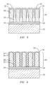
- FIG. 2 is a fragmented sectional view through a substrate, such as the turbine blade of FIG. 1, showing a TBC having a discrete parallel-grain structure and microcracks, and a top reaction product after heat treatment;
- FIG. 3 is a fragmented sectional view through a substrate, such as the turbine blade of FIG. 1, showing a TBC having a discrete columnar-grain structure and intercolumnar gaps, and a top reaction product after heat treatment with a continuous sheath coating, and
- FIG. 4 is a fragmented sectional view similar to FIG. 3, showing the top reaction product with a discontinuous sheath coating forming a plurality of nodules.
- the invention described herein employs several basic concepts. For example, one concept relates to new and additional multiphase TBCs that tend to be relatively easier to chemically form, manufacture, or arrange onto a basecoat or superalloy substrate, as well as relatively less expensive than that of the prior art. Another concept relates to continuing and improving upon existing multiphase TBCs adapted for prolonged exposure to temperatures above approximately 1200° C. and even above approximately 1400° C.
- the present invention is disclosed in context of use as a TBC for a superalloy combustion turbine blade.
- the principles of the present invention are not limited to TBC's for superalloy combustion turbine blades.
- the TBC can be used with other turbine components such as vanes, transitions, ring segments, buckets, nozzles, combustor cans, heat shields, and the like.
- the TBC can be more generally used with any metal or ceramic based substrate or layer where thermal protection is required or helpful, for example, atmospheric reentry vehicles.
- the blade 10 has a leading edge 12 , an airfoil section 14 against which hot combustion gases are directed during turbine operation and which is subject to thermal stresses, oxidation and corrosion, and a root section 16 that anchors the blade 10 .
- Cooling passages 18 may be optionally present through the blade 10 to allow cooling air to transfer heat from the blade 10 .
- the blade 10 advantageously can be made from a high temperature resistant nickel or cobalt based superalloy, for example, one comprising a combination of Ni and Cr.Al.Co.Ta.Mo.W, such as CM247 commercially available from the Cannon Muskegan Corporation located in Muskegan, Mich.
- a TBC 20 covers at least a portion of the turbine blade 10 .
- the TBC 20 advantageously comprises a base layer 28 and one or more overlays 32 that form a reaction product 32 ′ upon heat treatment.
- One or more optional bond layers 24 , 26 can be arranged between the TBC 20 and turbine blade 10 .
- the optional bond layer 24 forms the first layer on the turbine blade 10 (more generally, the substrate 10 ).
- the bond layer 24 typically comprises either alumina or MCrAlY, where M is a metal selected from the group consisting of Co, Ni and mixtures or combinations thereof, and Y is selected from the group consisting of Y, La, Hf.
- Pt and/or Re can be incorporated into the bond layer 24 composition.
- the bond layer 24 can be applied by sputtering, electron beam vapor deposition, low pressure plasma spraying and the like, to provide a dense relatively uniform layer of about 0.02 mm to about 0.3 mm thick. This bond layer 24 can be subsequently polished to provide a smooth finished layer.
- the bond layer 24 is to allow an oxide scale 26 predominately comprising alumina to form in order to further protect the blade 10 from oxidative attack.
- the bond coat 24 also provides a good bonding surface for the TBC 20 .
- Various combinations of one or more underlayers 24 , 26 can be used, or the TBC can be applied directly onto the substrate blade 10 .
- the base layer 28 is deposited onto either the bond layer 24 (as shown) or directly onto the substrate 10 (not shown) via an APS or PVD process described below.
- the base layer 28 can be a single-oxide having the chemical formula denoted by AxOy, where A is selected from the group consisting of: Al, Ca, Mg, Zr, Y, Sc, La, Ce, Pr, Nd, Pm, Sm, Eu, Gd, Dy, Ho, E, T, Yb, Ta, Nb combinations thereof and the like. Since only a single-oxide is used, variable x can be the integers 1, 2 and 3, and variable y can be the integers 1, 2, 3, 4, and 5.
- a preferred single oxide base material 28 is yttria (Y 2 O 3 ).
- the base layer 28 can be a mixture of two oxides having the chemical formula denoted by A x1 O y1 and B x11 O y11 or more simply (A,B)xOy, where A and B are selected from the group consisting of: Al, Ca, Mg, Zr, Y, Sc, La, Ce, Pr, Nd, Pm, Sm, Eu, Gd, Dy, Ho, Er, Tm, Yb, Ta, Nb combinations thereof and the like.
- a preferred two-oxide base material 28 is yttria (Y 2 O 3 ) and zirconia (ZrO 2 ), with the yttria content ranging from 10 wt. % to 60 wt. % of the overall base material 28 .
- variable x and y will accordingly change. Moreover, if different A and B oxides are used, then variable x and y will further change.
- the listing below illustrates exemplary x and y variance. Without performing the forgoing basic mathematical calculations for each possible chemical combination, variable x tends to range from about 0.4 to about 2.0, and variable y tends to range from about 0.8 to about 2.9.
- a oxide Y (Y 2 O 3 )
- B oxide Zr (ZrO 2 ) weight % of Y 2 O 3 equation (A,B) x O y 10 (Y 0.11 Zr 0.89 ) 0.82 O 1.59 20 (Y 0.21 Zr 0.79 ) 0.83 O 1.56 30 (Y 0.32 Zr 0.68 ) 0.83 O 1.53 40 (Y 0.42 Zr 0.58 ) 0.84 O 1.51 50 (Y 0.52 Zr 0.48 ) 0.85 O 1.48 60 (Y 0.62 Zr 0.38 ) 0.86 O 1.45
- the overlay layer 32 is deposited as a precursor coating on top of the underlying base layer 28 via a process that allows for topside deposition and infiltration in between the PVD deposited gaps or cracks, or the APS deposited cracks or pores.
- Suitable deposition techniques include electron beam evaporation, air plasma spray, chemical vapor deposition, sol-gel, combinations thereof and the like.
- the overlay layer 32 can be a single-oxide having the chemical formula denoted by CwOz, where C is selected from the group consisting of: Al, Ca, Mg, Zr, Y, Sc, La, Ce, Pr, Nd, Pm, Sm, Eu, Gd, Dy, Ho, E, T, Yb, Ta, Nb combinations thereof and the like. Since only a single oxide is used, variable w can be the integers 1, 2 and 3, and variable z can be the integers 1, 2, 3, 4 and 5.
- a preferred single oxide overlay layer 32 is alumina (Al 2 O 3 ). It is also preferred that composition C not be the same as compositions A or B, since use of similar compositions tends not to yield desired reaction products.
- the overlay precursor layer 28 can be a mixture of two oxides having the chemical formula denoted by C w1 O z1 and D w11 O z11 or more simply (C,D)wOz, where C and D are selected from the group consisting of: Al, Ca, Mg, Zr, Y, Sc, La, Ce, Pr, Nd, Pm, Sm, Eu, Gd, Dy, Ho, Er, Tm, Yb, Ta, Nb combinations thereof and the like.
- variables w and z are not restricted to integer values and may be decimals as easily understood and calculable by those skilled in the art, with w being a decimal ranging from about 0.5 to about 1.5 and z being a decimal ranging from about 0.5 to about 2.0.
- the base layer 28 and the overlay layer 32 are allowed to chemically react by heating the reactants 28 , 32 to about 1200-1500° C. or other suitable means in order to induce the reaction.
- Overlay layer 32 is thereby transformed into a new overlay phase/material 32 ′ formed on the top surface of the TBC 20 .
- the exact composition of the final reaction product 32 ′ may vary, dependent on the phase stability of the two reactants 28 , 32 and the final reaction product desired at the surface temperature during service.
- the reaction product 32 ′ should be in thermodynamic equilibrium with the overall TBC 20 and should not completely dissolve into the TBC 20 upon long term service even at high temperatures, which ensures the stability of the multiphase TBC 20 .
- the thickness of the final reaction product 32 ′ can vary between about 0.0002 micrometers (2 Angstrom units) to about 10 micrometers.
- CaO stabilized ZrO 2 (Ca 0.38 Zr 0.62 ) 1 O 1.62 +0.1TiO 2 ⁇ 0.1CaTiO 3 +0.94(Ca 0.32 Zr 0.68 ) 1.06 O 1.62
- MgO stabilized ZrO 2 (Mg 0.46 Zr 0.54 ) 1 O 1.54 +0.1TiO 2 ⁇ 0.1MgTiO 3 +0.94(Mg 0.46 Zr 0.54 ) 1.07 O 1.54
- MgO stabilized ZrO 2 (Mg 0.46 Zr 0 54 ) 1 O 1.54 +0.1Al 2 O 3 ⁇ .01MgAl 2 O 4 +0.935(Mg 0.4 Zr 0.6 ) 0.9625 O 1.54
- Y 2 O 3 stabilized ZrO 2 : (Y 0.32 Zr 0.68 ) 1.19 O 2.19 +0.1Al 2 O 3 ⁇ 0.04Y 3 Al 5 O 12 +0.92(Y 0.2422 Zr 0.7578 ) 1.16 O 2.19
- Yb 2 O 3 stabilized ZrO 2 : (Yb 0.21 Zr 0.79 ) 1.12 O 2.12 +0.1Al 2 O 3 ⁇ 0.04Yb 3 Al 5 O 12 +0.92(Yb 0.1166 Zr 0.8834 ) 1.09 O 2.12
- Y 2 O 3 stabilized HfO 2 : (Y 0.39 Hf 0.61 ) 1.24 O 2.24 +0.1Al 2 O 3 ⁇ 0.04Y 3 Al 5 O 12 +0.91(Y 0.3288 Hf 0.6712 ) 1.24 O 2.24
- Yb 2 O 3 stabilized HfO 2 : (Yb 0.27 Hf 0.73 ) 1.16 O 2 +0.1Al 2 O 3 ⁇ 0.04Yb 3 Al 5 O 12 +0.91(Yb 0.1866 Hf 0.8134 ) 1.13 O 2.16
- Y 2 O 3 stabilized TiO 2 : (Y 0.23 Ti 0.77 ) 1.13 O 2.13 +0.1Al 2 O 3 ⁇ 0.1Al 2 TiO 5 +0.93(Y 0.252 Ti 0.747 ) 1.11 O 2.13
- Yb 2 O 3 stabilized TiO 2 : (Yb 0.15 Ti 0.85 ) 1.08 O 2.08 +0.1Al 2 O 3 ⁇ 0.1Al 2 TiO 5 +0.90(Yb 0.165 Ti 0.835 ) 1.08 O 2.08
- Multiphase TBCs 20 possess a unique set of properties, which the individual constituents may not provide.
- the multiphase TBC 20 comprises materials, compositions and/or phases that have formed as a result of a reaction between two or more materials or compositions 28 , 32 that have been deposited onto the substrate 10 .
- the materials or compositions 28 , 32 are advantageously selected based on their phase stability and possible reaction products.
- the reaction products 32 ′ that subsequently form part of the TBC 20 are selected such that they are phase stable to high temperatures, possess low thermal conductivity and have a low tendency to sinter.
- the reaction product 32 ′ can be selected to provide improved corrosion and erosion resistance.
- the multiphase TBC 20 can be applied by any one or more methods that provide good adherence in a thickness effective to provide the required thermal protection for the substrate 10 , preferably APS or PVD, and usually in the order of about 50 micrometers to about 350 micrometers.
- an APS method can be used to deposit the base layer 28 to provide a microstructure well known by those skilled in the art.
- a microstructure is characterized by a generally flat, planar or horizontal grain structure 40 with discrete microfissures or intersplat cracks 30 and pores or volumes 34 that extend generally parallel to the top surface of the substrate 10 (FIG. 2 ).
- the base layer 28 microstructure consists of solidified splats of the molten ceramic 28 that have microfissures 30 and volumes 34 formed during the deposition process and arranged within and/or between the splats.
- the strain tolerance of the TBC 20 results due to these microfissures 30 and volumes 34 within the splats.
- a PVD method can be used to deposit the base layer 28 to provide another microstructure well known by those skilled in the art.
- a microstructure is characterized by a generally columnar or vertical grain structure 40 with discrete microcracks, volumes or gaps 30 that extend generally perpendicular to the top surface of the substrate 10 (FIGS. 3 and 4 ).
- the reaction product 32 ′ can form a continuous coating over the entire column 40 FIG. 3 ), a discontinuous nodules 34 ′′ (FIG. 4 ), or other morphologies such as rivulets, grains, cracks, flakes, combinations thereof and the like (not shown).
- Non continuous coating morphologies can enhance the break up of intermitted bridges and the like that can form between the adjacent columns 40 or gaps 18 , 30 upon regular thermal cycling, thus maintaining and improving the strain tolerance of the TBC.
- An APS, PVD or other method could then be used to apply the overlay layer 32 on top of the base layer 28 .
- the applied overlay layer 32 material can thereby infiltrate into the cracks, gaps, and volumes 30 , 34 by gravity, absorption, adsorption, capillary action and the like.
- the base layer 28 and overlay layer 32 can be reacted to form the reaction product 32 ′ and multiphase TBC 20 .
- the temperature of the TBC 20 decreases across the thickness of the TBC 20 from the top outside surface to the substrate 10 .
- the infiltration depth of the overlay layer 32 should be more closely controlled. Modification of the deposition parameters can control the depth of infiltration of the overlay layer 32 into the base layer 28 , and consequently the depth of the reaction product 32 ′ across the thickness of the TBC 20 . The depth of the infiltration also depends on the variation of the volumes 30 , 34 from the exposed TBC surface to the TBC/substrate interface.
- the thickness of the underlying base layer 32 and the overlay layer 28 can be modified to obtain a specific thickness and volume of the reaction product 32 ′.
- the total thickness of the final multiphase TBC system 20 should range in the order of about 50 micrometers to about 350 micrometers.
- reaction products 32 ′ need not have a high thermal expansion.
- the thermal expansion mismatch between the reaction product 32 ′ and the underlying TBC 20 can be allowed to be sufficiently high, however, to introduce cracks in the reaction product 32 ′ due to coefficient of thermal expansion mismatch stress. This can be beneficial in breaking up any bonds that may have formed during sintering.
- An example of a processing method of the invention involves subjecting a standard Ni-based superalloy turbine component substrate 10 having a MCrAlY bond coat 24 and an alumina formed overlayer 26 to standard ceramic YSZ deposition by APS or PVD.
- the YSZ thereby forms the base layer 28 having microcracks 30 and/or pores 34 .
- An alumina overcoat layer 32 is then deposited over the base layer 28 via a vapor deposition technique and allowed to infiltrate into the base layer 28 .
- the coated substrate 10 , 28 , 32 is then heated to initiate a reaction between the Al 2 O 3 overlay layer 32 and the infiltrated YSZ base layer 32 to form a reaction product material 32 ′ containing major amounts of Y 3 Al 5 O 12 , a yttrium aluminum garnet (YAG) as the finalized overcoat material 32 ′, with the underlying base layer 28 as yttrium stabilized zirconia.
- YAG yttrium aluminum garnet
- This exemplary YAG multiphase TBC 10 has a unique combination of low thermal conductivity, high thermal expansion, long term phase stability and good strain compliance.
- the high thermal expansion, low thermal conductivity and long term phase stability could be provided by the YSZ base layer 28 .
- 10-60YSZ is phase stable as a cubic crystal structure upon long term exposure and also has low thermal conductivity of 1-2 W/mK (Watt/meter °Kelvin).
- the presence of Y 2 O 3 in the stabilized zirconia would aid in the sintering of the TBC, but due to its presence the strain compliance of the coating could be expected to be somewhat compromised. This could be is alleviated by the formation of the YAG reaction product 32 ′.
- YAG has a low thermal conductivity—lower than 2-3 W/mK at temperatures higher than 1000° C. In addition, even at about 1400° C., the reaction product does not show a tendency to sinter. Since the reaction product 32 ′ can also be formed between the cracks 30 and/or volumes 34 , the coating should also be strain compliant. Also, the reaction product 32 ′ is in thermodynamic equilibrium with the overall TBC 10 , which helps ensure the presence of the reaction product 32 ′ over the long term service of the component 10 . Thus, this exemplary multiphase TBC 10 can be used at very high temperatures for long term exposure while the reaction product 32 ′ functions as at least one of a sintering inhibitor, a corrosion resistant coating, an erosion resistant coating, and a low thermal conductivity coating.
Landscapes
- Chemical & Material Sciences (AREA)
- Engineering & Computer Science (AREA)
- Materials Engineering (AREA)
- Mechanical Engineering (AREA)
- Chemical Kinetics & Catalysis (AREA)
- Metallurgy (AREA)
- Organic Chemistry (AREA)
- General Engineering & Computer Science (AREA)
- Inorganic Chemistry (AREA)
- Turbine Rotor Nozzle Sealing (AREA)
- Other Surface Treatments For Metallic Materials (AREA)
Abstract
Description
| A oxide = Y (Y2O3) | B oxide = Zr (ZrO2) | ||
| weight % of Y2O3 | equation (A,B)xOy | ||
| 10 | (Y0.11Zr0.89)0.82O1.59 | ||
| 20 | (Y0.21Zr0.79)0.83O1.56 | ||
| 30 | (Y0.32Zr0.68)0.83O1.53 | ||
| 40 | (Y0.42Zr0.58)0.84O1.51 | ||
| 50 | (Y0.52Zr0.48)0.85O1.48 | ||
| 60 | (Y0.62Zr0.38)0.86O1.45 | ||
Claims (14)
Priority Applications (1)
| Application Number | Priority Date | Filing Date | Title |
|---|---|---|---|
| US10/157,569 US6677064B1 (en) | 2002-05-29 | 2002-05-29 | In-situ formation of multiphase deposited thermal barrier coatings |
Applications Claiming Priority (1)
| Application Number | Priority Date | Filing Date | Title |
|---|---|---|---|
| US10/157,569 US6677064B1 (en) | 2002-05-29 | 2002-05-29 | In-situ formation of multiphase deposited thermal barrier coatings |
Publications (2)
| Publication Number | Publication Date |
|---|---|
| US20040001977A1 US20040001977A1 (en) | 2004-01-01 |
| US6677064B1 true US6677064B1 (en) | 2004-01-13 |
Family
ID=29778531
Family Applications (1)
| Application Number | Title | Priority Date | Filing Date |
|---|---|---|---|
| US10/157,569 Expired - Lifetime US6677064B1 (en) | 2002-05-29 | 2002-05-29 | In-situ formation of multiphase deposited thermal barrier coatings |
Country Status (1)
| Country | Link |
|---|---|
| US (1) | US6677064B1 (en) |
Cited By (25)
| Publication number | Priority date | Publication date | Assignee | Title |
|---|---|---|---|---|
| US20040115470A1 (en) * | 2002-12-12 | 2004-06-17 | Ackerman John Frederick | Thermal barrier coating protected by infiltrated alumina and method for preparing same |
| US20050129869A1 (en) * | 2003-12-12 | 2005-06-16 | General Electric Company | Article protected by a thermal barrier coating having a group 2 or 3/group 5 stabilization-composition-enriched surface |
| US20060068189A1 (en) * | 2004-09-27 | 2006-03-30 | Derek Raybould | Method of forming stabilized plasma-sprayed thermal barrier coatings |
| US20060245984A1 (en) * | 2001-09-26 | 2006-11-02 | Siemens Power Generation, Inc. | Catalytic thermal barrier coatings |
| US20070172676A1 (en) * | 2003-04-04 | 2007-07-26 | Siemens Westinghouse Power Corporation | Thermal barrier coating having nano scale features |
| US20080145643A1 (en) * | 2006-12-15 | 2008-06-19 | United Technologies Corporation | Thermal barrier coating |
| US20100172760A1 (en) * | 2009-01-06 | 2010-07-08 | General Electric Company | Non-Integral Turbine Blade Platforms and Systems |
| US20100202873A1 (en) * | 2009-02-06 | 2010-08-12 | General Electric Company | Ceramic Matrix Composite Turbine Engine |
| US20100209718A1 (en) * | 2007-08-02 | 2010-08-19 | Kabushiki Kaisha Kobe Seiko Sho (Kobe Steel Ltd.) | Oxide film, oxide film coated material and method for forming an oxide film |
| US7858205B2 (en) | 2007-09-19 | 2010-12-28 | Siemens Energy, Inc. | Bimetallic bond layer for thermal barrier coating on superalloy |
| US20100327213A1 (en) * | 2009-06-30 | 2010-12-30 | Honeywell International Inc. | Turbine engine components |
| US20110027556A1 (en) * | 2009-07-31 | 2011-02-03 | Glen Harold Kirby | Slurry compositions for making environmental barrier coatings and environmental barrier coatings comprising the same |
| US20110027467A1 (en) * | 2009-07-31 | 2011-02-03 | Glen Harold Kirby | Methods of making environmental barrier coatings for high temperature ceramic components using sintering aids |
| US20110229632A1 (en) * | 2009-07-31 | 2011-09-22 | Glen Harold Kirby | Methods of improving surface roughness of an environmental barrier coating and components comprising environmental barrier coatings having imrpoved surface roughness |
| US20120164471A1 (en) * | 2010-12-27 | 2012-06-28 | Hon Hai Precision Industry Co., Ltd. | Housing and method for making the same |
| US20120189867A1 (en) * | 2011-01-26 | 2012-07-26 | Hon Hai Precision Industry Co., Ltd. | Housing and method for making the same |
| US20120189865A1 (en) * | 2011-01-25 | 2012-07-26 | Hon Hai Precision Industry Co., Ltd. | Housing and method for making the same |
| US8347636B2 (en) | 2010-09-24 | 2013-01-08 | General Electric Company | Turbomachine including a ceramic matrix composite (CMC) bridge |
| US8951644B2 (en) | 2007-09-19 | 2015-02-10 | Siemens Energy, Inc. | Thermally protective multiphase precipitant coating |
| US9056802B2 (en) | 2009-07-31 | 2015-06-16 | General Electric Company | Methods for making environmental barrier coatings using sintering aids |
| US9212100B2 (en) | 2009-07-31 | 2015-12-15 | General Electric Company | Environmental barrier coatings for high temperature ceramic components |
| US9428825B1 (en) * | 2012-02-01 | 2016-08-30 | U.S. Department Of Energy | MCrAlY bond coat with enhanced yttrium |
| WO2017218759A1 (en) * | 2016-06-15 | 2017-12-21 | The Penn State Research Foundation | Thermal barrier coatings |
| US20180016919A1 (en) * | 2016-07-12 | 2018-01-18 | Delavan Inc | Thermal barrier coatings with enhanced reflectivity |
| US10435793B2 (en) | 2008-04-11 | 2019-10-08 | Sensor Coating Systems Limited | Thermal barrier coatings and coated components |
Families Citing this family (14)
| Publication number | Priority date | Publication date | Assignee | Title |
|---|---|---|---|---|
| US7935387B2 (en) * | 2004-10-20 | 2011-05-03 | Ues, Inc. | Methods for fabricating YAG barrier coatings |
| JP4815797B2 (en) * | 2004-12-14 | 2011-11-16 | 船井電機株式会社 | Photodetector |
| EP1959099B1 (en) * | 2004-12-14 | 2011-06-15 | Mitsubishi Heavy Industries, Ltd. | A Method for Manufacturing a Member Coated with a Thermal Barrier |
| JP4325648B2 (en) * | 2005-10-24 | 2009-09-02 | トヨタ自動車株式会社 | Catalyst carrier and exhaust gas purification catalyst |
| US20070224359A1 (en) * | 2006-03-22 | 2007-09-27 | Burin David L | Method for preparing strain tolerant coatings by a sol-gel process |
| US20090239061A1 (en) * | 2006-11-08 | 2009-09-24 | General Electric Corporation | Ceramic corrosion resistant coating for oxidation resistance |
| US10423421B2 (en) * | 2012-12-28 | 2019-09-24 | Intel Corporation | Opportunistic utilization of redundant ALU |
| US9869188B2 (en) | 2014-12-12 | 2018-01-16 | General Electric Company | Articles for high temperature service and method for making |
| US10472286B2 (en) * | 2015-02-10 | 2019-11-12 | University Of Connecticut | Yttrium aluminum garnet based thermal barrier coatings |
| FR3042137B1 (en) * | 2015-10-07 | 2017-12-01 | Safran | TURBOMACHINE PIECE COATED WITH A CERAMIC PROTECTIVE COATING, METHOD OF MANUFACTURING AND USING SUCH A PIECE |
| DE102016206968A1 (en) * | 2016-04-25 | 2017-10-26 | Siemens Aktiengesellschaft | Heat shield with extreme yttria coating, method of manufacture and product |
| US10822696B2 (en) | 2016-12-14 | 2020-11-03 | General Electric Company | Article with thermal barrier coating and method for making |
| CN112225551B (en) * | 2020-10-19 | 2021-11-23 | 清华大学 | Rare earth zirconate/rare earth aluminate eutectic thermal barrier coating material with high fracture toughness and preparation method thereof |
| US20240343917A1 (en) * | 2023-04-14 | 2024-10-17 | Raytheon Technologies Corporation | Environmental barrier coating and method of applying the same |
Citations (20)
| Publication number | Priority date | Publication date | Assignee | Title |
|---|---|---|---|---|
| US2869227A (en) | 1955-07-01 | 1959-01-20 | Armour Res Found | Process of coating and hot working of metals |
| FR2163369A1 (en) | 1971-12-16 | 1973-07-27 | Inst Metallurg Ime | Application of non-metallic coatings to metals - by application of an inter coating |
| US4916022A (en) | 1988-11-03 | 1990-04-10 | Allied-Signal Inc. | Titania doped ceramic thermal barrier coatings |
| EP0389959A1 (en) | 1989-03-28 | 1990-10-03 | Castolin S.A. | Method for applying corrosion and abrasion protective coatings |
| EP0455451A1 (en) | 1990-04-30 | 1991-11-06 | E.I. Du Pont De Nemours And Company | Thermal shock resistant ceramic honeycomb structures |
| US5238752A (en) | 1990-05-07 | 1993-08-24 | General Electric Company | Thermal barrier coating system with intermetallic overlay bond coat |
| US5350599A (en) | 1992-10-27 | 1994-09-27 | General Electric Company | Erosion-resistant thermal barrier coating |
| JPH0725690A (en) | 1993-07-07 | 1995-01-27 | Mitsubishi Materials Corp | Method for forming metallized layer of AlN substrate |
| US5562998A (en) | 1994-11-18 | 1996-10-08 | Alliedsignal Inc. | Durable thermal barrier coating |
| US5573862A (en) | 1992-04-13 | 1996-11-12 | Alliedsignal Inc. | Single crystal oxide turbine blades |
| US5683825A (en) | 1996-01-02 | 1997-11-04 | General Electric Company | Thermal barrier coating resistant to erosion and impact by particulate matter |
| US5716720A (en) | 1995-03-21 | 1998-02-10 | Howmet Corporation | Thermal barrier coating system with intermediate phase bondcoat |
| US5721057A (en) | 1993-02-04 | 1998-02-24 | Mtu Motoren-Und Turbinen-Union Munchen Gmgh | Ceramic, heat insulation layer on metal structural part and process for its manufacture |
| US5763107A (en) | 1994-12-24 | 1998-06-09 | Rolls-Royce Plc | Thermal barrier coating for a superalloy article |
| US5780110A (en) | 1995-12-22 | 1998-07-14 | General Electric Company | Method for manufacturing thermal barrier coated articles |
| US5824423A (en) | 1996-02-07 | 1998-10-20 | N.V. Interturbine | Thermal barrier coating system and methods |
| US5846605A (en) | 1992-03-05 | 1998-12-08 | Rolls-Royce Plc | Coated Article |
| US6203927B1 (en) * | 1999-02-05 | 2001-03-20 | Siemens Westinghouse Power Corporation | Thermal barrier coating resistant to sintering |
| US6294260B1 (en) | 1999-09-10 | 2001-09-25 | Siemens Westinghouse Power Corporation | In-situ formation of multiphase air plasma sprayed barrier coatings for turbine components |
| US6296945B1 (en) | 1999-09-10 | 2001-10-02 | Siemens Westinghouse Power Corporation | In-situ formation of multiphase electron beam physical vapor deposited barrier coatings for turbine components |
-
2002
- 2002-05-29 US US10/157,569 patent/US6677064B1/en not_active Expired - Lifetime
Patent Citations (20)
| Publication number | Priority date | Publication date | Assignee | Title |
|---|---|---|---|---|
| US2869227A (en) | 1955-07-01 | 1959-01-20 | Armour Res Found | Process of coating and hot working of metals |
| FR2163369A1 (en) | 1971-12-16 | 1973-07-27 | Inst Metallurg Ime | Application of non-metallic coatings to metals - by application of an inter coating |
| US4916022A (en) | 1988-11-03 | 1990-04-10 | Allied-Signal Inc. | Titania doped ceramic thermal barrier coatings |
| EP0389959A1 (en) | 1989-03-28 | 1990-10-03 | Castolin S.A. | Method for applying corrosion and abrasion protective coatings |
| EP0455451A1 (en) | 1990-04-30 | 1991-11-06 | E.I. Du Pont De Nemours And Company | Thermal shock resistant ceramic honeycomb structures |
| US5238752A (en) | 1990-05-07 | 1993-08-24 | General Electric Company | Thermal barrier coating system with intermetallic overlay bond coat |
| US5846605A (en) | 1992-03-05 | 1998-12-08 | Rolls-Royce Plc | Coated Article |
| US5573862A (en) | 1992-04-13 | 1996-11-12 | Alliedsignal Inc. | Single crystal oxide turbine blades |
| US5350599A (en) | 1992-10-27 | 1994-09-27 | General Electric Company | Erosion-resistant thermal barrier coating |
| US5721057A (en) | 1993-02-04 | 1998-02-24 | Mtu Motoren-Und Turbinen-Union Munchen Gmgh | Ceramic, heat insulation layer on metal structural part and process for its manufacture |
| JPH0725690A (en) | 1993-07-07 | 1995-01-27 | Mitsubishi Materials Corp | Method for forming metallized layer of AlN substrate |
| US5562998A (en) | 1994-11-18 | 1996-10-08 | Alliedsignal Inc. | Durable thermal barrier coating |
| US5763107A (en) | 1994-12-24 | 1998-06-09 | Rolls-Royce Plc | Thermal barrier coating for a superalloy article |
| US5716720A (en) | 1995-03-21 | 1998-02-10 | Howmet Corporation | Thermal barrier coating system with intermediate phase bondcoat |
| US5780110A (en) | 1995-12-22 | 1998-07-14 | General Electric Company | Method for manufacturing thermal barrier coated articles |
| US5683825A (en) | 1996-01-02 | 1997-11-04 | General Electric Company | Thermal barrier coating resistant to erosion and impact by particulate matter |
| US5824423A (en) | 1996-02-07 | 1998-10-20 | N.V. Interturbine | Thermal barrier coating system and methods |
| US6203927B1 (en) * | 1999-02-05 | 2001-03-20 | Siemens Westinghouse Power Corporation | Thermal barrier coating resistant to sintering |
| US6294260B1 (en) | 1999-09-10 | 2001-09-25 | Siemens Westinghouse Power Corporation | In-situ formation of multiphase air plasma sprayed barrier coatings for turbine components |
| US6296945B1 (en) | 1999-09-10 | 2001-10-02 | Siemens Westinghouse Power Corporation | In-situ formation of multiphase electron beam physical vapor deposited barrier coatings for turbine components |
Cited By (40)
| Publication number | Priority date | Publication date | Assignee | Title |
|---|---|---|---|---|
| US20060245984A1 (en) * | 2001-09-26 | 2006-11-02 | Siemens Power Generation, Inc. | Catalytic thermal barrier coatings |
| US7541005B2 (en) * | 2001-09-26 | 2009-06-02 | Siemens Energy Inc. | Catalytic thermal barrier coatings |
| US20040170849A1 (en) * | 2002-12-12 | 2004-09-02 | Ackerman John Frederick | Thermal barrier coating protected by infiltrated alumina and method for preparing same |
| US20040115470A1 (en) * | 2002-12-12 | 2004-06-17 | Ackerman John Frederick | Thermal barrier coating protected by infiltrated alumina and method for preparing same |
| US20070172676A1 (en) * | 2003-04-04 | 2007-07-26 | Siemens Westinghouse Power Corporation | Thermal barrier coating having nano scale features |
| US7413798B2 (en) * | 2003-04-04 | 2008-08-19 | Siemens Power Generation, Inc. | Thermal barrier coating having nano scale features |
| US20100291302A1 (en) * | 2003-12-12 | 2010-11-18 | General Electric Company | Article protected by a thermal barrier coating having a group 2 or 3/group 5 stabilization-composition-enriched surface |
| US20050129869A1 (en) * | 2003-12-12 | 2005-06-16 | General Electric Company | Article protected by a thermal barrier coating having a group 2 or 3/group 5 stabilization-composition-enriched surface |
| US20060068189A1 (en) * | 2004-09-27 | 2006-03-30 | Derek Raybould | Method of forming stabilized plasma-sprayed thermal barrier coatings |
| US20080145643A1 (en) * | 2006-12-15 | 2008-06-19 | United Technologies Corporation | Thermal barrier coating |
| US20100209718A1 (en) * | 2007-08-02 | 2010-08-19 | Kabushiki Kaisha Kobe Seiko Sho (Kobe Steel Ltd.) | Oxide film, oxide film coated material and method for forming an oxide film |
| US8465852B2 (en) * | 2007-08-02 | 2013-06-18 | Kobe Steel, Ltd. | Oxide film, oxide film coated material and method for forming an oxide film |
| US8951644B2 (en) | 2007-09-19 | 2015-02-10 | Siemens Energy, Inc. | Thermally protective multiphase precipitant coating |
| US7858205B2 (en) | 2007-09-19 | 2010-12-28 | Siemens Energy, Inc. | Bimetallic bond layer for thermal barrier coating on superalloy |
| US10435793B2 (en) | 2008-04-11 | 2019-10-08 | Sensor Coating Systems Limited | Thermal barrier coatings and coated components |
| US20100172760A1 (en) * | 2009-01-06 | 2010-07-08 | General Electric Company | Non-Integral Turbine Blade Platforms and Systems |
| US8382436B2 (en) | 2009-01-06 | 2013-02-26 | General Electric Company | Non-integral turbine blade platforms and systems |
| US8262345B2 (en) | 2009-02-06 | 2012-09-11 | General Electric Company | Ceramic matrix composite turbine engine |
| US20100202873A1 (en) * | 2009-02-06 | 2010-08-12 | General Electric Company | Ceramic Matrix Composite Turbine Engine |
| US20100327213A1 (en) * | 2009-06-30 | 2010-12-30 | Honeywell International Inc. | Turbine engine components |
| US8449994B2 (en) | 2009-06-30 | 2013-05-28 | Honeywell International Inc. | Turbine engine components |
| US8986779B2 (en) | 2009-07-31 | 2015-03-24 | General Electric Company | Methods of improving surface roughness of an environmental barrier coating and components comprising environmental barrier coatings having improved surface roughness |
| US20110229632A1 (en) * | 2009-07-31 | 2011-09-22 | Glen Harold Kirby | Methods of improving surface roughness of an environmental barrier coating and components comprising environmental barrier coatings having imrpoved surface roughness |
| US20110027556A1 (en) * | 2009-07-31 | 2011-02-03 | Glen Harold Kirby | Slurry compositions for making environmental barrier coatings and environmental barrier coatings comprising the same |
| US9212100B2 (en) | 2009-07-31 | 2015-12-15 | General Electric Company | Environmental barrier coatings for high temperature ceramic components |
| US9073793B2 (en) | 2009-07-31 | 2015-07-07 | General Electric Company | Slurry compositions for making environmental barrier coatings and environmental barrier coatings comprising the same |
| US9056802B2 (en) | 2009-07-31 | 2015-06-16 | General Electric Company | Methods for making environmental barrier coatings using sintering aids |
| US20110027467A1 (en) * | 2009-07-31 | 2011-02-03 | Glen Harold Kirby | Methods of making environmental barrier coatings for high temperature ceramic components using sintering aids |
| US8347636B2 (en) | 2010-09-24 | 2013-01-08 | General Electric Company | Turbomachine including a ceramic matrix composite (CMC) bridge |
| US8597783B2 (en) * | 2010-12-27 | 2013-12-03 | Hong Fu Jin Precision Industry (Shenzhen) Co., Ltd. | Housing and method for making the same |
| US20120164471A1 (en) * | 2010-12-27 | 2012-06-28 | Hon Hai Precision Industry Co., Ltd. | Housing and method for making the same |
| US8597782B2 (en) * | 2011-01-25 | 2013-12-03 | Hong Fu Jin Precision Industry (Shenzhen) Co., Ltd. | Housing and method for making the same |
| US20120189865A1 (en) * | 2011-01-25 | 2012-07-26 | Hon Hai Precision Industry Co., Ltd. | Housing and method for making the same |
| US8603627B2 (en) * | 2011-01-26 | 2013-12-10 | Hong Fu Jin Precision Industry (Shenzhen) Co., Ltd. | Housing and method for making the same |
| US20120189867A1 (en) * | 2011-01-26 | 2012-07-26 | Hon Hai Precision Industry Co., Ltd. | Housing and method for making the same |
| US9428825B1 (en) * | 2012-02-01 | 2016-08-30 | U.S. Department Of Energy | MCrAlY bond coat with enhanced yttrium |
| WO2017218759A1 (en) * | 2016-06-15 | 2017-12-21 | The Penn State Research Foundation | Thermal barrier coatings |
| EP3471959A4 (en) * | 2016-06-15 | 2020-04-15 | The Penn State Research Foundation | Thermal barrier coatings |
| US11739410B2 (en) | 2016-06-15 | 2023-08-29 | The Penn State Research Foundation | Thermal barrier coatings |
| US20180016919A1 (en) * | 2016-07-12 | 2018-01-18 | Delavan Inc | Thermal barrier coatings with enhanced reflectivity |
Also Published As
| Publication number | Publication date |
|---|---|
| US20040001977A1 (en) | 2004-01-01 |
Similar Documents
| Publication | Publication Date | Title |
|---|---|---|
| US6677064B1 (en) | In-situ formation of multiphase deposited thermal barrier coatings | |
| US6294260B1 (en) | In-situ formation of multiphase air plasma sprayed barrier coatings for turbine components | |
| EP1214460B1 (en) | In-situ formation of multiphase electron beam physical vapor deposited barrier coatings for turbine components | |
| US6365281B1 (en) | Thermal barrier coatings for turbine components | |
| US6387539B1 (en) | Thermal barrier coating having high phase stability | |
| EP1335040B1 (en) | Method of forming a coating resistant to deposits | |
| JP4401576B2 (en) | Apparatus and manufacturing method having a sinter resistant thermal insulation coating | |
| US6440575B1 (en) | Ceramic thermal barrier layer for gas turbine engine component | |
| US6548190B2 (en) | Low thermal conductivity thermal barrier coating system and method therefor | |
| US6730413B2 (en) | Thermal barrier coating | |
| US9790587B2 (en) | Article and method of making thereof | |
| EP1840238A2 (en) | Oxidation-resistant coating and formation method thereof, thermal barrier coating, heat-resistant member, and gas turbine | |
| KR20030068054A (en) | Hybrid thermal barrier coating and method of making the same | |
| JP2003160852A (en) | Thermal insulating coating material, manufacturing method therefor, turbine member and gas turbine | |
| CN112756232A (en) | Repair coating system and method | |
| WO2014022285A1 (en) | Localized transitional coating of turbine components | |
| CN101291806A (en) | Durable heat shield coating with low thermal conductivity | |
| EP2225409A2 (en) | Coating system | |
| JP2003342751A (en) | Heat-resistant structural member and manufacturing method thereof | |
| JPH0978257A (en) | Thermal barrier coating material | |
| KR101166150B1 (en) | Durable thermal barrier coating having low thermal conductivity | |
| JPH10273787A (en) | Heat resistant member and method of manufacturing the same | |
| Subramanian et al. | Thermal barrier coating resistant to sintering |
Legal Events
| Date | Code | Title | Description |
|---|---|---|---|
| AS | Assignment |
Owner name: SIEMENS WESTINGHOUSE POWER CORPORATION, FLORIDA Free format text: ASSIGNMENT OF ASSIGNORS INTEREST;ASSIGNOR:SUBRAMANIAN, RAMESH;REEL/FRAME:012953/0293 Effective date: 20020528 |
|
| STCF | Information on status: patent grant |
Free format text: PATENTED CASE |
|
| AS | Assignment |
Owner name: ENERGY, UNITED STATES DEPARTMENT OF, DISTRICT OF C Free format text: CONFIRMATORY LICENSE;ASSIGNOR:SIEMENS WESTINGHOUSE POWER CORPORATION;REEL/FRAME:015085/0430 Effective date: 20040115 |
|
| AS | Assignment |
Owner name: SIEMENS POWER GENERATION, INC., FLORIDA Free format text: CHANGE OF NAME;ASSIGNOR:SIEMENS WESTINGHOUSE POWER CORPORATION;REEL/FRAME:016996/0491 Effective date: 20050801 |
|
| FPAY | Fee payment |
Year of fee payment: 4 |
|
| AS | Assignment |
Owner name: SIEMENS ENERGY, INC., FLORIDA Free format text: CHANGE OF NAME;ASSIGNOR:SIEMENS POWER GENERATION, INC.;REEL/FRAME:022482/0740 Effective date: 20081001 Owner name: SIEMENS ENERGY, INC.,FLORIDA Free format text: CHANGE OF NAME;ASSIGNOR:SIEMENS POWER GENERATION, INC.;REEL/FRAME:022482/0740 Effective date: 20081001 |
|
| FPAY | Fee payment |
Year of fee payment: 8 |
|
| FPAY | Fee payment |
Year of fee payment: 12 |