US6676223B2 - Automotive wheel having a foot step - Google Patents
Automotive wheel having a foot step Download PDFInfo
- Publication number
- US6676223B2 US6676223B2 US10/132,778 US13277802A US6676223B2 US 6676223 B2 US6676223 B2 US 6676223B2 US 13277802 A US13277802 A US 13277802A US 6676223 B2 US6676223 B2 US 6676223B2
- Authority
- US
- United States
- Prior art keywords
- disk
- wheel
- pedestal
- retractable foot
- hub
- Prior art date
- Legal status (The legal status is an assumption and is not a legal conclusion. Google has not performed a legal analysis and makes no representation as to the accuracy of the status listed.)
- Expired - Lifetime
Links
Images


Classifications
-
- B—PERFORMING OPERATIONS; TRANSPORTING
- B60—VEHICLES IN GENERAL
- B60B—VEHICLE WHEELS; CASTORS; AXLES FOR WHEELS OR CASTORS; INCREASING WHEEL ADHESION
- B60B7/00—Wheel cover discs, rings, or the like, for ornamenting, protecting, venting, or obscuring, wholly or in part, the wheel body, rim, hub, or tyre sidewall, e.g. wheel cover discs, wheel cover discs with cooling fins
- B60B7/0026—Wheel cover discs, rings, or the like, for ornamenting, protecting, venting, or obscuring, wholly or in part, the wheel body, rim, hub, or tyre sidewall, e.g. wheel cover discs, wheel cover discs with cooling fins characterised by the surface
- B60B7/0066—Wheel cover discs, rings, or the like, for ornamenting, protecting, venting, or obscuring, wholly or in part, the wheel body, rim, hub, or tyre sidewall, e.g. wheel cover discs, wheel cover discs with cooling fins characterised by the surface the dominant aspect being the surface structure
-
- B—PERFORMING OPERATIONS; TRANSPORTING
- B60—VEHICLES IN GENERAL
- B60B—VEHICLE WHEELS; CASTORS; AXLES FOR WHEELS OR CASTORS; INCREASING WHEEL ADHESION
- B60B7/00—Wheel cover discs, rings, or the like, for ornamenting, protecting, venting, or obscuring, wholly or in part, the wheel body, rim, hub, or tyre sidewall, e.g. wheel cover discs, wheel cover discs with cooling fins
- B60B7/06—Fastening arrangements therefor
- B60B7/061—Fastening arrangements therefor characterised by the part of the wheels to which the discs, rings or the like are mounted
- B60B7/068—Fastening arrangements therefor characterised by the part of the wheels to which the discs, rings or the like are mounted to the wheel bolts or wheel nuts
-
- B—PERFORMING OPERATIONS; TRANSPORTING
- B60—VEHICLES IN GENERAL
- B60B—VEHICLE WHEELS; CASTORS; AXLES FOR WHEELS OR CASTORS; INCREASING WHEEL ADHESION
- B60B7/00—Wheel cover discs, rings, or the like, for ornamenting, protecting, venting, or obscuring, wholly or in part, the wheel body, rim, hub, or tyre sidewall, e.g. wheel cover discs, wheel cover discs with cooling fins
- B60B7/06—Fastening arrangements therefor
- B60B7/14—Fastening arrangements therefor comprising screw-threaded means
Definitions
- the present invention relates to automotive vehicles, and more particularly to the wheels thereof. Still more particularly, the present invention relates to an automotive wheel having incorporated a selectively retractable foot step.
- the wheel well area is a vehicular location frequently used by bystanders to access parts of the vehicle located over the fenders, it would be most beneficial if somehow the vehicle, itself, could provide a step where the wheel is located.
- the present invention is an automotive wheel incorporating a selectively retractable foot step.
- An automotive wheel has a centrally disposed, circular wheel opening defined by a wheel opening periphery.
- a pedestal composed of a drum and a disk integrally connected to the drum, is located at the wheel opening, wherein the disk has a disk periphery which is rotatably interfaced with the wheel opening periphery.
- a step is pivotally connected to the pedestal.
- the disk has a disk cut-out configured for receiving therein the step. The step is pivotal from a retracted position whereat the step is parallel to the disk (that is, parallel to the plane of the wheel) and received in the disk cut-out, to a deployed position whereat the step is perpendicular to the disk.
- a retainer is used to selectively hold the step at the retracted position.
- a user may use the step as a safe and secure foot step to access parts of the vehicle thereabove.
- the lug nuts are accessible through the disk cut-out for removal or installation of the wheel with respect to the axle hub.
- the drum is bolted to the axle hub, wherein the disk periphery slides on the wheel opening periphery.
- a user places the step into the deployed position, and then manually rotates the step into a horizontal attitude for being used as a foot step.
- the drum is mounted to the axle hub via a bearing, and the disk is weighted so that gravity always causes the step to assume a horizontal attitude. In operation, all the user need do is pivot the step to the deployed position for using it as a foot step.
- FIG. 1 is a side view of an automotive wheel equipped with a retractable foot, step according to the present invention, shown in operation with respect to a motor vehicle.
- FIG. 2A is a side view of the retractable foot step, shown with the step at the retracted position.
- FIG. 2B is a side view of the retractable foot step, shown with the step at the deployed position.
- FIG. 3 is a perspective view of the retractable foot step, showing the step at the deployed position and being operationally used as a foot step.
- FIG. 4 is a broken-away end view of the retractable foot step, showing the step at the deployed position and being operationally used as a foot step.
- FIG. 5 is a broken-away top view of the retractable foot step, shown with the step at the deployed position.
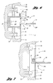
- FIG. 6 is a partly sectional view taken along line 6 — 6 in FIG. 2 B.
- FIG. 7 is a partly sectional view taken along line 7 — 7 in FIG. 2 B.
- FIG. 8 is a partly sectional view of an alternative embodiment of a retractable foot step according to the present invention, seen taken from a vantage similar to that taken at FIG. 6 .
- FIGS. 1 through 7 depict an example of a retractable foot step 10 according to the present invention.
- the retractable foot step 10 includes a pedestal 12 (shown at FIG. 6) located at a central portion of a wheel 14 .
- the pedestal 12 includes a disk 16 and a drum 26 which are preferably integrally formed as a single piece.
- the disk 16 has a circular disk periphery 18 .
- the wheel 14 has a central opening 20 (see FIGS. 6 and 7) defined by a wheel opening periphery 22 , which is slidably interfaced with the disk periphery 18 such that the pedestal is freely rotatable with respect to the wheel.
- a step 24 is pivotally connected to the pedestal 12 .
- the disk 16 has a disk cut-out 16 C having a shape complementary to the shape of the step 24 such that the step is received into the disk cut-out when pivoted to an orientation parallel to the disk (parallel to the wheel plane P in FIG. 6 ), referred to herein as the retracted position, as shown at FIGS. 1 and 2A.
- the step 24 is pivotal from the retracted position to a deployed position whereat the step is perpendicular to the step assembly disk 16 (perpendicular to the wheel plane), as shown at FIGS. 2B and 5.
- the step 24 serves as a convenient and sturdy foot step for a user to step upon and thereby gain increased height to access portions of the vehicle thereabove, as generally shown at FIGS. 3 and 4.
- FIGS. 6 and 7 structural aspects of the preferred embodiment of the retractable foot step 10 will be detailed.
- the aforementioned peripheral interface of the disk periphery 18 with the wheel opening periphery 22 is in the form of the wheel opening periphery having an inner lip 22 L which serves as a mechanical locating feature and slide surface between the wheel and the disk.
- the drum 26 has a floor 26 F through which passes a mounting bolt 28 that threads into a threaded hole 30 in the axle hub 32 , whereby the disk 16 is rotatably mounted to the axle hub and, consequently, rotatable with respect to the wheel 14 .
- the mounting bolt may be threadably engaged with the wheel if the wheel has a continuous center portion, rather than a central aperture as shown at FIG. 6 .
- An access panel 25 provides easy accessibility to the mounting bolt 28 for removal and installation purposes.
- the step 24 it is preferred for the step 24 to have a U-shape defined by left and right step arms 24 L, 24 R which are mutually connected at a distal end thereof by a platform 24 P as shown in FIG. 5 .
- the near ends of the left and right step arms 24 L, 24 R, respectively, have a perpendicularly projecting ledge 34 .
- the step 24 is pivotally connected to the pedestal 12 via a respective pivot pin 36 L, 36 R passing through the ledge 34 of each of the left and right step arms 24 L, 24 R and through an adjacent mounting block 38 , which is integrally connected with the disk 16 (for example a nut threaded onto a bushing lined bolt).
- the pivot pins may pass into the drum.
- FIG. 6 shows a preferred retainer in the form of a spring loaded retainer pin 42 which is slidable in a pin guide passage 40 formed in the pedestal 12 .
- the retainer pin 42 has a pin head 42 H and a pin release button 42 B, wherein a spring 42 S biases the pin head upwardly toward the disk cut-out 16 C.
- the pin head 42 H enters into a pin seat 44 of the step platform 24 P so as to interfere with pivoting of the step out from the retracted position unless the release button 42 B is intentionally depressed in opposition to spring biasing of the retainer pin.
- a locating tab 45 provides location of the step 24 with respect to the disk 16 A with respect to the retracted position.
- a spring steel release 46 may be mounted to the step assembly disk 16 which serves to bias the step 24 when it is placed into the retracted position, wherein the biasing provides a spring force to kick-out the step from the retracted position as soon as the pin head 42 H has been depressed.
- a user depresses the pin release button 42 B, whereupon the step 24 kicks-out and is then moved into the fully deployed position.
- the step is not already horizontal, the user then grabs the step and rotates it relative to the wheel 14 so that it is brought into a reasonably horizontal attitude.
- the interaction of the pivot pins 36 L, 36 R vis-a-vis the left and right step arms 24 L, 24 R abutting a bottom edge 48 of the disk cut-out 16 C of the step assembly disk 16 provide a stable support for the user to step upon as shown at FIGS. 3 and 4.
- the disk cut-out 16 C provides an opening through the disk 16 of ample size for a lug wrench to successively engage all the lug nuts L by simply rotating the pedestal successively as needed for access to each.
- the user After using the step, the user simply pivots it back to the retracted position, whereupon the retainer automatically retentively engages the step.
- FIG. 8 depicts a variation of the retractable foot step 10 ′, having a pedestal 12 ′ and pivotally mounted step 24 , wherein like numbers indicate like parts to those mentioned with regard to FIGS. 6 and 7.
- the pedestal 12 ′ has a low friction bearing (ie., a roller or ball bearing) 50 which interconnects the drum 26 ′ to the wheel hub 32 (or to the wheel 14 ).
- the periphery interface between the wheel opening periphery 22 ′ and the disk periphery 18 ′ now has a small gap G to eliminate friction therebetween.
- a weight 52 is attached to the disk 12 ′ at a location vertically below the horizontal plane of the step.
- step 24 always having a horizontal attitude.
- An alternative retainer using a magnet 54 and a handholded step 24 ′ is depicted; however, the aforedescribed retainer using a pin would be more preferable.
Landscapes
- Engineering & Computer Science (AREA)
- Mechanical Engineering (AREA)
- Vehicle Step Arrangements And Article Storage (AREA)
Abstract
Description
Claims (17)
Priority Applications (1)
| Application Number | Priority Date | Filing Date | Title |
|---|---|---|---|
| US10/132,778 US6676223B2 (en) | 2002-04-25 | 2002-04-25 | Automotive wheel having a foot step |
Applications Claiming Priority (1)
| Application Number | Priority Date | Filing Date | Title |
|---|---|---|---|
| US10/132,778 US6676223B2 (en) | 2002-04-25 | 2002-04-25 | Automotive wheel having a foot step |
Publications (2)
| Publication Number | Publication Date |
|---|---|
| US20030201664A1 US20030201664A1 (en) | 2003-10-30 |
| US6676223B2 true US6676223B2 (en) | 2004-01-13 |
Family
ID=29248837
Family Applications (1)
| Application Number | Title | Priority Date | Filing Date |
|---|---|---|---|
| US10/132,778 Expired - Lifetime US6676223B2 (en) | 2002-04-25 | 2002-04-25 | Automotive wheel having a foot step |
Country Status (1)
| Country | Link |
|---|---|
| US (1) | US6676223B2 (en) |
Cited By (8)
| Publication number | Priority date | Publication date | Assignee | Title |
|---|---|---|---|---|
| US20040012245A1 (en) * | 2002-07-19 | 2004-01-22 | Ptasinski Zygmunt James | Tire step |
| US20060181137A1 (en) * | 2005-02-14 | 2006-08-17 | Kolpasky Kevin G | Automotive wheel having a foot step |
| US7413205B2 (en) * | 2005-09-27 | 2008-08-19 | Magna International Inc. | Retractable sidestep |
| US20100301580A1 (en) * | 2009-05-30 | 2010-12-02 | Gm Global Technology Operations, Inc. | Vehicle with step assembly |
| US9120426B1 (en) | 2014-02-07 | 2015-09-01 | Ford Global Technologies, Llc | Wheelhouse cladding step |
| US11458900B2 (en) | 2019-04-29 | 2022-10-04 | Magna Exteriors Inc. | Multi position automated running board |
| US11541816B2 (en) | 2018-04-13 | 2023-01-03 | Magna Exteriors Inc. | Power box side step |
| US11919481B2 (en) | 2019-04-09 | 2024-03-05 | Magna Exteriors, Inc. | Retractable power step remote drive |
Families Citing this family (1)
| Publication number | Priority date | Publication date | Assignee | Title |
|---|---|---|---|---|
| US10807411B2 (en) | 2015-04-13 | 2020-10-20 | Ford Global Technologies, Llc | Wheel with spokes including integral step providing improved access to a cargo bed of a motor vehicle |
Citations (9)
| Publication number | Priority date | Publication date | Assignee | Title |
|---|---|---|---|---|
| US1149338A (en) * | 1914-05-12 | 1915-08-10 | Joseph A Butcher | Vehicle-step. |
| US2218060A (en) * | 1939-09-09 | 1940-10-15 | Watson Thomas | Step for motor vehicles |
| US3288488A (en) * | 1965-04-30 | 1966-11-29 | Jack E Shinn | Combined hubcap and step tread construction |
| US3734534A (en) * | 1971-04-22 | 1973-05-22 | P Brooks | Mounting step for automotive vehicle |
| US3773355A (en) * | 1971-06-18 | 1973-11-20 | C Swartz | Bicycle passenger foot support |
| US4440411A (en) * | 1982-06-17 | 1984-04-03 | Hess Walter R | Vehicle hub step |
| US5456479A (en) * | 1994-06-27 | 1995-10-10 | Conger; Ronald S. | Truck access step |
| US5634694A (en) * | 1995-10-19 | 1997-06-03 | Uretech International, Inc. | Wheel assembly and elastomeric guard member |
| US6457558B1 (en) * | 2000-03-20 | 2002-10-01 | Steve L. Ehnes | Tire step apparatus |
-
2002
- 2002-04-25 US US10/132,778 patent/US6676223B2/en not_active Expired - Lifetime
Patent Citations (9)
| Publication number | Priority date | Publication date | Assignee | Title |
|---|---|---|---|---|
| US1149338A (en) * | 1914-05-12 | 1915-08-10 | Joseph A Butcher | Vehicle-step. |
| US2218060A (en) * | 1939-09-09 | 1940-10-15 | Watson Thomas | Step for motor vehicles |
| US3288488A (en) * | 1965-04-30 | 1966-11-29 | Jack E Shinn | Combined hubcap and step tread construction |
| US3734534A (en) * | 1971-04-22 | 1973-05-22 | P Brooks | Mounting step for automotive vehicle |
| US3773355A (en) * | 1971-06-18 | 1973-11-20 | C Swartz | Bicycle passenger foot support |
| US4440411A (en) * | 1982-06-17 | 1984-04-03 | Hess Walter R | Vehicle hub step |
| US5456479A (en) * | 1994-06-27 | 1995-10-10 | Conger; Ronald S. | Truck access step |
| US5634694A (en) * | 1995-10-19 | 1997-06-03 | Uretech International, Inc. | Wheel assembly and elastomeric guard member |
| US6457558B1 (en) * | 2000-03-20 | 2002-10-01 | Steve L. Ehnes | Tire step apparatus |
Non-Patent Citations (3)
| Title |
|---|
| "TIRE-HOPPER" Tire Step product sheets of Top Line Mfg., Paramount, CA, 2 pages. First publication date unknown. |
| Tire Step product sheets of AutoSport, Charlottesville, VA 22906, 2 pages. First public date unknown. |
| Tire Step product sheets of Proline Products, Inc., Wallingford, CT 06492, 4 pages. First publication date unknown. |
Cited By (13)
| Publication number | Priority date | Publication date | Assignee | Title |
|---|---|---|---|---|
| US20040012245A1 (en) * | 2002-07-19 | 2004-01-22 | Ptasinski Zygmunt James | Tire step |
| US6869150B2 (en) * | 2002-07-19 | 2005-03-22 | Zygmunt James Ptasinski | Tire step |
| US20060181137A1 (en) * | 2005-02-14 | 2006-08-17 | Kolpasky Kevin G | Automotive wheel having a foot step |
| US7270381B2 (en) | 2005-02-14 | 2007-09-18 | Gm Global Technology Operations, Inc. | Automotive wheel having a foot step |
| US7607674B2 (en) * | 2005-09-27 | 2009-10-27 | Magna International | Retractable sidestep |
| US20080246244A1 (en) * | 2005-09-27 | 2008-10-09 | Magna International Inc. | Retractable sidestep |
| US7413205B2 (en) * | 2005-09-27 | 2008-08-19 | Magna International Inc. | Retractable sidestep |
| US20100301580A1 (en) * | 2009-05-30 | 2010-12-02 | Gm Global Technology Operations, Inc. | Vehicle with step assembly |
| US8038164B2 (en) * | 2009-05-30 | 2011-10-18 | GM Global Technology Operations LLC | Vehicle with step assembly |
| US9120426B1 (en) | 2014-02-07 | 2015-09-01 | Ford Global Technologies, Llc | Wheelhouse cladding step |
| US11541816B2 (en) | 2018-04-13 | 2023-01-03 | Magna Exteriors Inc. | Power box side step |
| US11919481B2 (en) | 2019-04-09 | 2024-03-05 | Magna Exteriors, Inc. | Retractable power step remote drive |
| US11458900B2 (en) | 2019-04-29 | 2022-10-04 | Magna Exteriors Inc. | Multi position automated running board |
Also Published As
| Publication number | Publication date |
|---|---|
| US20030201664A1 (en) | 2003-10-30 |
Similar Documents
| Publication | Publication Date | Title |
|---|---|---|
| US6592135B2 (en) | Vehicle running board detachable for use as loading ramp | |
| CA2437055C (en) | Improved attachment means for facilitating user access to vehicle platforms | |
| US6840526B2 (en) | Bumper step | |
| US5460304A (en) | Modular vehicular carrier system | |
| US7198443B2 (en) | Motorcycle transport system and method therefor | |
| US7222763B2 (en) | Pivoting support arrangement for maintaining a bicycle wheel in an upright position | |
| US6202909B1 (en) | Storable hitch mounted cargo carrier | |
| US6676223B2 (en) | Automotive wheel having a foot step | |
| US5579973A (en) | Carrier for lightweight two wheel vehicles, with capability for also towing a trailer | |
| US5829774A (en) | Combination step and bumper assembly and method | |
| US20060108297A1 (en) | Rack for securing a vehicle | |
| US20020125677A1 (en) | Stowable steps | |
| US7434825B2 (en) | Deployable step for motor vehicles | |
| US4679717A (en) | Spare tire carrier | |
| US20010001636A1 (en) | Hydraulic lift for motor home | |
| US20070245783A1 (en) | Adjustable Two-Piece Vehicle Immobilizer | |
| US5857824A (en) | Dirt bike carrier | |
| US6554311B1 (en) | Step plate assembly for providing a step while preserving access to the hitch ball of a hitch assembly | |
| US7410081B2 (en) | Support structure for a spare tire on a vehicle | |
| US4099771A (en) | Seat adapted to be mounted on vehicle tire | |
| US10562431B2 (en) | Aftermarket stowable trailer ramp | |
| US5531560A (en) | Motorcycle towing device | |
| US6340106B1 (en) | Carrying rack for truck beds | |
| WO2012143881A1 (en) | Spare wheel carrier for a vehicle | |
| US11135960B2 (en) | Aftermarket stowable trailer ramp |
Legal Events
| Date | Code | Title | Description |
|---|---|---|---|
| AS | Assignment |
Owner name: GENERAL MOTORS CORPORATION, MICHIGAN Free format text: ASSIGNMENT OF ASSIGNORS INTEREST;ASSIGNOR:KOLPASKY, KEVIN G.;REEL/FRAME:013054/0323 Effective date: 20020417 |
|
| STCF | Information on status: patent grant |
Free format text: PATENTED CASE |
|
| FPAY | Fee payment |
Year of fee payment: 4 |
|
| AS | Assignment |
Owner name: GM GLOBAL TECHNOLOGY OPERATIONS, INC., MICHIGAN Free format text: ASSIGNMENT OF ASSIGNORS INTEREST;ASSIGNOR:GENERAL MOTORS CORPORATION;REEL/FRAME:022092/0755 Effective date: 20050119 Owner name: GM GLOBAL TECHNOLOGY OPERATIONS, INC.,MICHIGAN Free format text: ASSIGNMENT OF ASSIGNORS INTEREST;ASSIGNOR:GENERAL MOTORS CORPORATION;REEL/FRAME:022092/0755 Effective date: 20050119 |
|
| AS | Assignment |
Owner name: UNITED STATES DEPARTMENT OF THE TREASURY, DISTRICT Free format text: SECURITY AGREEMENT;ASSIGNOR:GM GLOBAL TECHNOLOGY OPERATIONS, INC.;REEL/FRAME:022201/0547 Effective date: 20081231 Owner name: UNITED STATES DEPARTMENT OF THE TREASURY,DISTRICT Free format text: SECURITY AGREEMENT;ASSIGNOR:GM GLOBAL TECHNOLOGY OPERATIONS, INC.;REEL/FRAME:022201/0547 Effective date: 20081231 |
|
| AS | Assignment |
Owner name: CITICORP USA, INC. AS AGENT FOR BANK PRIORITY SECU Free format text: SECURITY AGREEMENT;ASSIGNOR:GM GLOBAL TECHNOLOGY OPERATIONS, INC.;REEL/FRAME:022553/0399 Effective date: 20090409 Owner name: CITICORP USA, INC. AS AGENT FOR HEDGE PRIORITY SEC Free format text: SECURITY AGREEMENT;ASSIGNOR:GM GLOBAL TECHNOLOGY OPERATIONS, INC.;REEL/FRAME:022553/0399 Effective date: 20090409 |
|
| AS | Assignment |
Owner name: GM GLOBAL TECHNOLOGY OPERATIONS, INC., MICHIGAN Free format text: RELEASE BY SECURED PARTY;ASSIGNOR:UNITED STATES DEPARTMENT OF THE TREASURY;REEL/FRAME:023124/0470 Effective date: 20090709 Owner name: GM GLOBAL TECHNOLOGY OPERATIONS, INC.,MICHIGAN Free format text: RELEASE BY SECURED PARTY;ASSIGNOR:UNITED STATES DEPARTMENT OF THE TREASURY;REEL/FRAME:023124/0470 Effective date: 20090709 |
|
| AS | Assignment |
Owner name: GM GLOBAL TECHNOLOGY OPERATIONS, INC., MICHIGAN Free format text: RELEASE BY SECURED PARTY;ASSIGNORS:CITICORP USA, INC. AS AGENT FOR BANK PRIORITY SECURED PARTIES;CITICORP USA, INC. AS AGENT FOR HEDGE PRIORITY SECURED PARTIES;REEL/FRAME:023127/0273 Effective date: 20090814 Owner name: GM GLOBAL TECHNOLOGY OPERATIONS, INC.,MICHIGAN Free format text: RELEASE BY SECURED PARTY;ASSIGNORS:CITICORP USA, INC. AS AGENT FOR BANK PRIORITY SECURED PARTIES;CITICORP USA, INC. AS AGENT FOR HEDGE PRIORITY SECURED PARTIES;REEL/FRAME:023127/0273 Effective date: 20090814 |
|
| AS | Assignment |
Owner name: UNITED STATES DEPARTMENT OF THE TREASURY, DISTRICT Free format text: SECURITY AGREEMENT;ASSIGNOR:GM GLOBAL TECHNOLOGY OPERATIONS, INC.;REEL/FRAME:023156/0001 Effective date: 20090710 Owner name: UNITED STATES DEPARTMENT OF THE TREASURY,DISTRICT Free format text: SECURITY AGREEMENT;ASSIGNOR:GM GLOBAL TECHNOLOGY OPERATIONS, INC.;REEL/FRAME:023156/0001 Effective date: 20090710 |
|
| AS | Assignment |
Owner name: UAW RETIREE MEDICAL BENEFITS TRUST, MICHIGAN Free format text: SECURITY AGREEMENT;ASSIGNOR:GM GLOBAL TECHNOLOGY OPERATIONS, INC.;REEL/FRAME:023161/0911 Effective date: 20090710 Owner name: UAW RETIREE MEDICAL BENEFITS TRUST,MICHIGAN Free format text: SECURITY AGREEMENT;ASSIGNOR:GM GLOBAL TECHNOLOGY OPERATIONS, INC.;REEL/FRAME:023161/0911 Effective date: 20090710 |
|
| AS | Assignment |
Owner name: GM GLOBAL TECHNOLOGY OPERATIONS, INC., MICHIGAN Free format text: RELEASE BY SECURED PARTY;ASSIGNOR:UNITED STATES DEPARTMENT OF THE TREASURY;REEL/FRAME:025245/0347 Effective date: 20100420 Owner name: GM GLOBAL TECHNOLOGY OPERATIONS, INC., MICHIGAN Free format text: RELEASE BY SECURED PARTY;ASSIGNOR:UAW RETIREE MEDICAL BENEFITS TRUST;REEL/FRAME:025311/0725 Effective date: 20101026 |
|
| AS | Assignment |
Owner name: WILMINGTON TRUST COMPANY, DELAWARE Free format text: SECURITY AGREEMENT;ASSIGNOR:GM GLOBAL TECHNOLOGY OPERATIONS, INC.;REEL/FRAME:025327/0222 Effective date: 20101027 |
|
| AS | Assignment |
Owner name: GM GLOBAL TECHNOLOGY OPERATIONS LLC, MICHIGAN Free format text: CHANGE OF NAME;ASSIGNOR:GM GLOBAL TECHNOLOGY OPERATIONS, INC.;REEL/FRAME:025780/0795 Effective date: 20101202 |
|
| FPAY | Fee payment |
Year of fee payment: 8 |
|
| AS | Assignment |
Owner name: GM GLOBAL TECHNOLOGY OPERATIONS LLC, MICHIGAN Free format text: RELEASE BY SECURED PARTY;ASSIGNOR:WILMINGTON TRUST COMPANY;REEL/FRAME:034183/0680 Effective date: 20141017 |
|
| FPAY | Fee payment |
Year of fee payment: 12 |