US6672829B1 - Turbine blade having angled squealer tip - Google Patents
Turbine blade having angled squealer tip Download PDFInfo
- Publication number
- US6672829B1 US6672829B1 US10/196,623 US19662302A US6672829B1 US 6672829 B1 US6672829 B1 US 6672829B1 US 19662302 A US19662302 A US 19662302A US 6672829 B1 US6672829 B1 US 6672829B1
- Authority
- US
- United States
- Prior art keywords
- tip
- turbine blade
- rib
- tip rib
- angle
- Prior art date
- Legal status (The legal status is an assumption and is not a legal conclusion. Google has not performed a legal analysis and makes no representation as to the accuracy of the status listed.)
- Expired - Lifetime, expires
Links
Images


Classifications
-
- F—MECHANICAL ENGINEERING; LIGHTING; HEATING; WEAPONS; BLASTING
- F01—MACHINES OR ENGINES IN GENERAL; ENGINE PLANTS IN GENERAL; STEAM ENGINES
- F01D—NON-POSITIVE DISPLACEMENT MACHINES OR ENGINES, e.g. STEAM TURBINES
- F01D5/00—Blades; Blade-carrying members; Heating, heat-insulating, cooling or antivibration means on the blades or the members
- F01D5/12—Blades
- F01D5/14—Form or construction
- F01D5/141—Shape, i.e. outer, aerodynamic form
- F01D5/145—Means for influencing boundary layers or secondary circulations
-
- F—MECHANICAL ENGINEERING; LIGHTING; HEATING; WEAPONS; BLASTING
- F01—MACHINES OR ENGINES IN GENERAL; ENGINE PLANTS IN GENERAL; STEAM ENGINES
- F01D—NON-POSITIVE DISPLACEMENT MACHINES OR ENGINES, e.g. STEAM TURBINES
- F01D5/00—Blades; Blade-carrying members; Heating, heat-insulating, cooling or antivibration means on the blades or the members
- F01D5/12—Blades
- F01D5/14—Form or construction
- F01D5/20—Specially-shaped blade tips to seal space between tips and stator
-
- F—MECHANICAL ENGINEERING; LIGHTING; HEATING; WEAPONS; BLASTING
- F05—INDEXING SCHEMES RELATING TO ENGINES OR PUMPS IN VARIOUS SUBCLASSES OF CLASSES F01-F04
- F05D—INDEXING SCHEME FOR ASPECTS RELATING TO NON-POSITIVE-DISPLACEMENT MACHINES OR ENGINES, GAS-TURBINES OR JET-PROPULSION PLANTS
- F05D2250/00—Geometry
- F05D2250/20—Three-dimensional
- F05D2250/29—Three-dimensional machined; miscellaneous
- F05D2250/292—Three-dimensional machined; miscellaneous tapered
Definitions
- the present invention relates generally to turbine blades for a gas turbine engine and, in particular, to the cooling of the tip and the tip leakage flow of such turbine blades.
- the airfoil has a generally concave pressure side and generally convex suction side extending axially between corresponding leading and trailing edges and radially between a root and a tip. It will be understood that the blade tip is spaced closely to a radially outer turbine shroud for minimizing leakage therebetween of the combustion gases flowing downstream between the turbine blades. Maximum efficiency of the engine is obtained by minimizing the tip clearance or gap, but is limited by the differential thermal and mechanical expansion and contraction between the rotor blades and the turbine shroud for reducing the likelihood of undesirable tip rubs.
- the blade airfoils are hollow and disposed in flow communication with the compressor so that a portion of pressurized air bled therefrom is received for use in cooling the airfoils.
- Airfoil cooling is quite sophisticated and may be effected using various forms of internal cooling channels and features, as well as cooling holes through the walls of the airfoil for discharging the cooling air.
- the airfoil tip is particularly difficult to cool since it is located directly adjacent to the turbine shroud and the hot combustion gases which flow through the tip gap therebetween. Accordingly, a portion of the air channeled inside the airfoil is typically discharged through the tip for cooling thereof.
- the tip typically includes a continuous radially outwardly projecting edge rib disposed coextensively along the pressure and suction sides between the leading and trailing edges, where the tip rib follows the aerodynamic contour around the airfoil and is a significant contributor to the aerodynamic efficiency thereof.
- the tip rib has portions spaced apart on the opposite pressure and suction sides to define an open top tip cavity.
- a tip plate or floor extends between the pressure and suction side ribs and encloses the top of the airfoil for containing the cooling air therein.
- Tip holes are also provided which extend through the floor for cooling the tip and filling the tip cavity.
- a turbine blade tip to be developed which alters the pressure distribution near the tip region to reduce the overall tip leakage flow and thereby increase the efficiency of the turbine. It is also desirable for such turbine blade tip to develop one or more recirculation zones adjacent the ribs at such tip in order to improve the flow characteristics and pressure distribution at the tip region.
- a turbine blade for a gas turbine engine including an airfoil and integral dovetail for mounting the airfoil along a radial axis to a rotor disk inboard of a turbine shroud.
- the airfoil further includes: first and second sidewalls joined together at a leading edge and a trailing edge, where the first and second sidewalls extend from a root disposed adjacent the dovetail to a tip plate for channeling combustion gases thereover; and, at least one tip rib extending outwardly from the tip plate between the leading and trailing edges.
- the tip rib is oriented so that an axis extending longitudinally therethrough is at an angle with respect to the radial axis for at least a designated portion of an axial length of the turbine blade.
- the angle between the longitudinal axis and the radial axis may be substantially the same across the designated portion or may vary thereacross.
- a turbine blade for a gas turbine engine is disclosed as including an airfoil and integral dovetail for mounting the airfoil along a radial axis to a rotor disk inboard of a turbine shroud.
- the airfoil further includes: first and second sidewalls joined together at a leading edge and a trailing edge, where the first and second sidewalls extend from a root disposed adjacent the dovetail to a tip plate for channeling combustion gases thereover; and, at least one tip rib extending outwardly from the tip plate between the leading and trailing edges.
- the tip rib is oriented with respect to the radial axis so that a first recirculation zone of the combustion gases is formed adjacent a distal end of the tip rib which reduces a leakage flow of the combustion gases between the airfoil and the shroud for at least a designated portion of an axial length of the turbine blade.
- FIG. 1 is a partly sectional, isometric view of an exemplary gas turbine engine rotor blade mounted in a rotor disk within a surrounding shroud, with the blade having a tip in accordance with an exemplary embodiment of the present invention
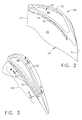
- FIG. 2 is an isometric view of the blade tip as illustrated in FIG. 1 having a pair of aerodynamic tip ribs in accordance with an exemplary embodiment
- FIG. 3 is a top view of the blade tip illustrated in FIGS. 1 and 2;
- FIG. 4 is an elevational, sectional view through the blade tip illustrated in FIG. 3 within the turbine shroud, taken generally along line 4 — 4 , and depicting a maximum angle between a longitudinal axis through the blade tip ribs and the radial axis;
- FIG. 5 is an elevational, sectional view through the blade tip illustrated in FIG. 3 within the turbine shroud, taken generally along line 5 — 5 , and depicting a minimum angle between a longitudinal axis through the blade tip ribs and the radial axis;
- FIG. 6 is an elevational, sectional view through an alternative blade tip like that illustrated in FIGS. 4 and 5, where a longitudinal axis through the blade tip rib at the pressure side of the airfoil forms an acute angle with respect to the radial axis and the blade tip rib at the suction side of the airfoil is substantially parallel to the radial axis;
- FIG. 7 is an elevational, sectional view through a second alternative blade tip like that illustrated in FIGS. 4 and 5, where a longitudinal axis through the blade tip rib at the suction side of the airfoil forms an acute angle with respect to the radial axis in the upstream direction and the blade tip rib at the pressure side of the airfoil is substantially parallel to the radial axis;
- FIG. 8 is an elevational, sectional view through a third alternative blade tip like that illustrated in FIGS. 4 and 5, where a longitudinal axis through the blade tip rib at the suction side of the airfoil forms an acute angle with respect to the radial axis in the downstream direction and the blade tip rib at the pressure side of the airfoil is substantially parallel to the radial axis;
- FIG. 9 is an elevational, sectional view through a fourth alternative blade tip like that illustrated in FIGS. 4 and 5, where a third intermediate blade tip rib is positioned between the blade tip ribs located adjacent the pressure and suction sides of the airfoil;
- FIG. 10A is an enlarged, partial sectional view through the blade tip illustrated in FIG. 4 within the turbine shroud depicting the flow of combustion gases adjacent the pressure side blade tip rib and through the gap between such rib and the turbine shroud;
- FIG. 10B is an enlarged, partial sectional view through the blade tip illustrated in FIG. 4 within the turbine shroud depicting the flow of combustion gases adjacent the suction side blade tip rib, the area between the pressure and suction side blade tip ribs, and through the gap between such ribs and the turbine shroud.
- FIG. 1 depicts a portion of a high pressure turbine 10 of a gas turbine engine which is mounted directly downstream from a combustor (not shown) for receiving hot combustion gases 12 therefrom.
- Turbine 10 which is axisymmetrical about an axial centerline axis 14 , includes a rotor disk 16 and a plurality of circumferentially spaced apart turbine rotor blades 18 (one of which being shown) extending radially outwardly from rotor disk 16 along a radial axis 17 .
- An annular turbine shroud 20 is suitably joined to a stationary stator casing (not shown) and surrounds blades 18 for providing a relatively small clearance or gap therebetween for limiting leakage of combustion gases 12 therethrough during operation.
- Each blade 18 preferably includes a dovetail 22 which may have any conventional form, such as an axial dovetail configured for being mounted in a corresponding dovetail slot in the perimeter of the rotor disk 16 .
- a hollow airfoil 24 is integrally joined to dovetail 22 and extends radially or longitudinally outwardly therefrom.
- Blade 18 also includes an integral platform 26 disposed at the junction of airfoil 24 and dovetail 22 for defining a portion of the radially inner flowpath for combustion gases 12 . It will be appreciated that blade 18 may be formed in any conventional manner, and is typically a one-piece casting.
- airfoil 24 preferably includes a generally concave first or pressure sidewall 28 and a circumferentially or laterally opposite, generally convex, second or suction sidewall 30 extending axially or chordally between opposite leading and trailing edges 32 and 34 , respectively.
- Sidewalls 28 and 30 also extend in the radial or longitudinal direction between a radially inner root 36 at platform 26 and a radially outer tip 38 .
- first and second sidewalls 28 and 30 are spaced apart in the lateral or circumferential direction over the entire longitudinal or radial span of airfoil 24 to define at least one internal flow chamber or channel 40 for channeling cooling air 42 through airfoil 24 for cooling thereof. Cooling air 42 is typically bled from the compressor (not shown) in any conventional manner.
- airfoil 24 may have any configuration including, for example, serpentine flow channels with various turbulators therein for enhancing cooling air effectiveness, with cooling air 42 being discharged through various holes through airfoil 24 such as conventional film cooling holes 44 and trailing edge discharge holes 46 .
- blade tip 38 preferably includes a tip floor or plate 48 disposed integrally atop the radially outer ends of first and second sidewalls 28 and 30 , where tip plate 48 bounds internal cooling channel 40 .
- a first tip wall or rib 50 preferably extends radially outwardly from tip plate 48 between leading and trailing edges 32 and 34 adjacent first (pressure) sidewall 28 .
- a second tip wall or rib 52 also preferably extends radially outwardly from tip plate 48 between leading and trailing edges 32 and 34 , and is spaced laterally from first tip rib 50 adjacent second (suction) sidewall 30 to define an open-top tip channel 54 therebetween.
- tip channel 54 is shown as being enclosed by first and second tip ribs 50 and 52 , it is consistent with the present invention for tip channel 54 to include a tip inlet and tip outlet as disclosed in U.S. Pat. No. 6,059,530 to Lee to assist in discharging combustion gases 12 through tip channel 54 .
- first tip rib 50 is preferably recessed from first sidewall 28 to form a tip shelf 56 substantially parallel to tip plate 48 as has been disclosed in the art to improve cooling of tip 38 .
- the present invention preferably provides that a longitudinal axis 58 extending through first tip rib 50 (see FIG. 4) be formed at an angle ⁇ to radial axis 17 for at least a designated portion 60 of an axial length of turbine blade 18 .
- angle ⁇ may be substantially the same or fixed across designated portion 60 , it is preferred that angle ⁇ vary across designated portion 60 as demonstrated by the change in angle ⁇ shown in FIGS. 4 and 5.
- angle ⁇ is preferably at a minimum (approximately 0°) at or adjacent both leading and trailing edges 32 and 34 , respectively.
- angle ⁇ preferably increases gradually to a maximum angle (depicted in FIG. 4 )located at a midpoint 62 on first tip rib 50 (see FIG. 3 ).
- Midpoint 62 is preferably located within designated portion 60 of first tip rib 50 , which is identified as approximately between one-fourth to three-fourths the distance from leading edge 32 to trailing edge 34 .
- angle ⁇ Due to the varying nature of angle ⁇ , it preferably is within a range of approximately 0°-70°, more preferably within a range of approximately 20°-65°, and optimally within a range of approximately 40°-60° as it changes within designated portion 60 .
- designated portion 60 is an axial length of airfoil 24 which preferably extends for approximately 5-95% of a chord through airfoil 24 .
- Designated portion 60 more preferably extends for approximately 7-80% of a chord through airfoil 24 and optimally extends for approximately 10-70% of a chord through airfoil 24 .
- first recirculation zone 64 of combustion gases 12 is formed adjacent a distal end 66 of first tip rib 50 .
- First recirculation zone 64 then functions to reduce the leakage flow of combustion gases (identified by flow arrows 68 ) and, in effect, shrink the size of a gap 70 between blade tip 38 and shroud 20 without risking a rub.
- flow arrows 68 the leakage flow of combustion gases
- recirculation zone 64 increases in size as angle ⁇ is increased.
- first tip rib 50 the depth of tip shelf 56 , and angle ⁇ between longitudinal axis 58 and radial axis 17 .
- a tangent of angle ⁇ is substantially equivalent to the depth of tip shelf 56 divided by the height of first tip rib 50 .
- Inherent limitations on tip shelf depth therefore translate into restrictions on angle ⁇ .
- modifications in the height of first tip rib 50 may be made since recirculation zone 64 serves to shrink the size of gap 70 as noted hereinabove. This means that angle ⁇ may increase by lessening the height of first rib tip 50 for a given tip shelf depth, which also has the advantage of lessening the risk of a rub between first rib tip 50 and shroud 20 .
- a pocket 72 is formed between a surface 74 of first tip rib 50 and tip shelf 56 which promotes a second recirculation zone 76 of combustion gases 12 to be formed therein. Since a plurality of cooling holes 78 are preferably provided within tip shelf 56 to provide a cooling film 80 along first tip rib surface 74 , pocket 72 and second recirculation zone 76 assist in maintaining cooling film 80 near first tip rib 50 (see FIG. 10 A). Accordingly, the flow of combustion gases 12 is deflected by first tip rib 50 and cooling film 80 and pushed away from gap 70 . This flow deflection therefore results in increased flow resistance for the leakage flow through gap 70 and maintains cooling film 80 to better cool first tip rib 50 .
- first tip rib 50 may be altered so as to be tapered longitudinally from a first end located adjacent tip plate 48 to distal end 66 , as disclosed in U.S. Pat. No. 6,190,129 to Mayer et al., so as to increase the cooling conduction thereof.
- Distal end 66 of first tip rib 50 may also be tapered in accordance with the teachings of U.S. Pat. No. 6,086,328 to Lee in order to reduce the thermal stress at such location so long as first recirculation zone 64 is preserved.
- first tip rib 50 may be inclined with respect to radial axis 17 and a longitudinal axis 82 of second tip rib 52 may remain substantially parallel to radial axis 17 . It is preferred, however, that second tip rib 52 be oriented so as to be substantially parallel to first tip rib 50 as it extends from leading edge 32 to trailing edge 34 at least within designated region 60 (see FIGS. 4 and 5) so that an angle J exists between longitudinal axis 82 and radial axis 17 .
- a third recirculation zone 84 is preferably formed at a distal end 86 of second tip rib 52 similar to first recirculation zone 64 described with respect to first tip rib 50 (see FIG. 10 B).
- Third recirculation zone 84 then assists in increasing the flow resistance through gap 70 like first recirculation zone 64 .
- a fourth recirculation zone 85 is generally formed within an area 87 located between first tip rib 50 and second tip rib 52 . Since recirculation of hot combustion gases 12 exists in area 87 , one or more cooling holes 89 are preferably formed through tip plate 48 .
- second tip rib 52 may be angled with respect to radial axis 17 while first tip rib 50 remains substantially parallel to radial axis 17 .
- This angle ⁇ may be at an acute angle in the upstream direction (herein referred to as the positive direction) as shown in FIG. 7 or at an acute angle with respect to radial axis 17 in the downstream direction (herein referred to as the negative direction) as shown in FIG. 8 .
- angle ⁇ will preferably have a range of approximately +60° to approximately ⁇ 60°.
- second rib tip 52 may be recessed with respect to suction sidewall 30 to form a tip shelf 88 when inclined in the negative (downstream) direction.
- third tip rib 90 located between first and second tip ribs 50 and 52 , respectively, similar to that described in U.S. Pat. No. 6,224,336 (see FIG. 9 ).
- third tip rib 90 is oriented so that a longitudinal axis 92 therethrough is substantially parallel to radial axis 17 .
- turbine blade and tip thereof can be accomplished by appropriate modifications by one of ordinary skill in the art without departing from the scope of the invention.
- certain turbine blades in the art which twist from their leading edge to their trailing edge and/or from their root to the tip may also utilize the rib tip configurations presented herein with appropriate modification so as to create the desired recirculation zones for decreasing tip leakage flow.
Landscapes
- Engineering & Computer Science (AREA)
- Mechanical Engineering (AREA)
- General Engineering & Computer Science (AREA)
- Physics & Mathematics (AREA)
- Fluid Mechanics (AREA)
- Turbine Rotor Nozzle Sealing (AREA)
Priority Applications (5)
| Application Number | Priority Date | Filing Date | Title |
|---|---|---|---|
| US10/196,623 US6672829B1 (en) | 2002-07-16 | 2002-07-16 | Turbine blade having angled squealer tip |
| EP03816841A EP1529153B1 (en) | 2002-07-16 | 2003-07-16 | Turbine blade having angled squealer tip |
| DE60321575T DE60321575D1 (de) | 2002-07-16 | 2003-07-16 | Turbinenschaufel mit einer geneigten rippe an der spitze |
| PCT/US2003/022663 WO2005014978A1 (en) | 2002-07-16 | 2003-07-16 | Turbine blade having angled squealer tip |
| JP2005507636A JP4386891B2 (ja) | 2002-07-16 | 2003-07-16 | 傾斜スキーラ先端を有するタービンブレード |
Applications Claiming Priority (1)
| Application Number | Priority Date | Filing Date | Title |
|---|---|---|---|
| US10/196,623 US6672829B1 (en) | 2002-07-16 | 2002-07-16 | Turbine blade having angled squealer tip |
Publications (2)
| Publication Number | Publication Date |
|---|---|
| US6672829B1 true US6672829B1 (en) | 2004-01-06 |
| US20040013515A1 US20040013515A1 (en) | 2004-01-22 |
Family
ID=29735375
Family Applications (1)
| Application Number | Title | Priority Date | Filing Date |
|---|---|---|---|
| US10/196,623 Expired - Lifetime US6672829B1 (en) | 2002-07-16 | 2002-07-16 | Turbine blade having angled squealer tip |
Country Status (5)
| Country | Link |
|---|---|
| US (1) | US6672829B1 (enExample) |
| EP (1) | EP1529153B1 (enExample) |
| JP (1) | JP4386891B2 (enExample) |
| DE (1) | DE60321575D1 (enExample) |
| WO (1) | WO2005014978A1 (enExample) |
Cited By (81)
| Publication number | Priority date | Publication date | Assignee | Title |
|---|---|---|---|---|
| US20040109754A1 (en) * | 2002-12-06 | 2004-06-10 | Townes Roderick M. | Blade cooling |
| US20040126236A1 (en) * | 2002-12-30 | 2004-07-01 | Ching-Pang Lee | Compound tip notched blade |
| US20040197190A1 (en) * | 2003-04-07 | 2004-10-07 | Stec Philip Francis | Turbine blade with recessed squealer tip and shelf |
| US20050095129A1 (en) * | 2003-10-31 | 2005-05-05 | Benjamin Edward D. | Methods and apparatus for assembling gas turbine engine rotor assemblies |
| US20050244270A1 (en) * | 2004-04-30 | 2005-11-03 | Siemens Westinghouse Power Corporation | Cooling system for a tip of a turbine blade |
| US20050281671A1 (en) * | 2004-06-17 | 2005-12-22 | Siemens Westinghouse Power Corporation | Gas turbine airfoil trailing edge corner |
| US20060051209A1 (en) * | 2004-09-09 | 2006-03-09 | Ching-Pang Lee | Fluted tip turbine blade |
| US20060067821A1 (en) * | 2004-09-28 | 2006-03-30 | Wadia Aspi R | Methods and apparatus for aerodynamically self-enhancing rotor blades |
| EP1650404A2 (en) | 2004-10-21 | 2006-04-26 | General Electric Company | Rebuild method of a turbine blade tip squealer |
| US7097419B2 (en) | 2004-07-26 | 2006-08-29 | General Electric Company | Common tip chamber blade |
| US20060257257A1 (en) * | 2005-05-13 | 2006-11-16 | Snecma | Hollow rotor blade for the turbine of a gas turbine engine, the blade being fitted with a "bathtub" |
| US20070059173A1 (en) * | 2005-09-09 | 2007-03-15 | General Electric Company | Turbine airfoil curved squealer tip with tip shelf |
| US20070059182A1 (en) * | 2005-09-09 | 2007-03-15 | General Electric Company | Turbine airfoil with curved squealer tip |
| EP1764477A1 (en) | 2005-09-14 | 2007-03-21 | General Electric Company | Fluted tip turbine blade |
| FR2891003A1 (fr) * | 2005-09-20 | 2007-03-23 | Snecma | Aube de turbomachine |
| EP1793087A1 (en) * | 2005-12-05 | 2007-06-06 | General Electric Company | Blunt tip turbine blade |
| US20070237637A1 (en) * | 2005-08-25 | 2007-10-11 | General Electric Company | Skewed tip hole turbine blade |
| US20080044289A1 (en) * | 2006-08-21 | 2008-02-21 | General Electric Company | Tip ramp turbine blade |
| US20080044290A1 (en) * | 2006-08-21 | 2008-02-21 | General Electric Company | Conformal tip baffle airfoil |
| US20080044291A1 (en) * | 2006-08-21 | 2008-02-21 | General Electric Company | Counter tip baffle airfoil |
| US20080131278A1 (en) * | 2006-11-30 | 2008-06-05 | Victor Hugo Silva Correia | Turbine blades and turbine blade cooling systems and methods |
| US7473073B1 (en) * | 2006-06-14 | 2009-01-06 | Florida Turbine Technologies, Inc. | Turbine blade with cooled tip rail |
| US20090092500A1 (en) * | 2005-06-24 | 2009-04-09 | Snecma | Hollow turbomachine blade |
| US7597539B1 (en) | 2006-09-27 | 2009-10-06 | Florida Turbine Technologies, Inc. | Turbine blade with vortex cooled end tip rail |
| US20090324422A1 (en) * | 2006-08-21 | 2009-12-31 | General Electric Company | Cascade tip baffle airfoil |
| US20100068063A1 (en) * | 2007-05-31 | 2010-03-18 | Richard Hiram Berg | Methods and apparatus for assembling gas turbine engines |
| US7695243B2 (en) | 2006-07-27 | 2010-04-13 | General Electric Company | Dust hole dome blade |
| US20100111674A1 (en) * | 2008-11-06 | 2010-05-06 | General Electric Company | System and Method for Reducing Bucket Tip Losses |
| US20100135822A1 (en) * | 2008-11-28 | 2010-06-03 | Remo Marini | Turbine blade for a gas turbine engine |
| US20100135813A1 (en) * | 2008-11-28 | 2010-06-03 | Remo Marini | Turbine blade for a gas turbine engine |
| US20100221122A1 (en) * | 2006-08-21 | 2010-09-02 | General Electric Company | Flared tip turbine blade |
| US20100290919A1 (en) * | 2009-05-12 | 2010-11-18 | George Liang | Gas Turbine Blade with Double Impingement Cooled Single Suction Side Tip Rail |
| US20100290920A1 (en) * | 2009-05-12 | 2010-11-18 | George Liang | Turbine Blade with Single Tip Rail with a Mid-Positioned Deflector Portion |
| US20100303625A1 (en) * | 2009-05-27 | 2010-12-02 | Craig Miller Kuhne | Recovery tip turbine blade |
| US20110044800A1 (en) * | 2004-08-06 | 2011-02-24 | Christian Cornelius | Compressor Blade and Production and Use of a Compressor Blade |
| CN102099549A (zh) * | 2008-07-21 | 2011-06-15 | 涡轮梅坎公司 | 用于涡轮转子的包括肋的中空叶片 |
| DE102010050712A1 (de) | 2010-11-08 | 2012-05-10 | Mtu Aero Engines Gmbh | Bauelement einer Strömungsmaschine und Verfahren zum generativen Herstellen eines derartigen Bauelementes |
| US8182221B1 (en) * | 2009-07-29 | 2012-05-22 | Florida Turbine Technologies, Inc. | Turbine blade with tip sealing and cooling |
| US8313287B2 (en) | 2009-06-17 | 2012-11-20 | Siemens Energy, Inc. | Turbine blade squealer tip rail with fence members |
| US8425183B2 (en) | 2006-11-20 | 2013-04-23 | General Electric Company | Triforial tip cavity airfoil |
| US20130266454A1 (en) * | 2012-04-05 | 2013-10-10 | United Technologies Corporation | Turbine airfoil tip shelf and squealer pocket cooling |
| US8777567B2 (en) | 2010-09-22 | 2014-07-15 | Honeywell International Inc. | Turbine blades, turbine assemblies, and methods of manufacturing turbine blades |
| US20140260324A1 (en) * | 2013-03-14 | 2014-09-18 | Pratt & Whitney Canada Corp. | Turbo-machinery rotors with rounded tip edge |
| US20140322028A1 (en) * | 2011-11-17 | 2014-10-30 | Snecma | Gas turbine blade with tip sections offset towards the pressure side and with cooling channels |
| US8920124B2 (en) | 2013-02-14 | 2014-12-30 | Siemens Energy, Inc. | Turbine blade with contoured chamfered squealer tip |
| US20150110617A1 (en) * | 2013-10-23 | 2015-04-23 | General Electric Company | Turbine airfoil including tip fillet |
| US9045988B2 (en) | 2012-07-26 | 2015-06-02 | General Electric Company | Turbine bucket with squealer tip |
| US9181814B2 (en) | 2010-11-24 | 2015-11-10 | United Technology Corporation | Turbine engine compressor stator |
| US9284845B2 (en) | 2012-04-05 | 2016-03-15 | United Technologies Corporation | Turbine airfoil tip shelf and squealer pocket cooling |
| US9328617B2 (en) | 2012-03-20 | 2016-05-03 | United Technologies Corporation | Trailing edge or tip flag antiflow separation |
| US9470096B2 (en) | 2012-07-26 | 2016-10-18 | General Electric Company | Turbine bucket with notched squealer tip |
| US9482101B2 (en) | 2012-11-28 | 2016-11-01 | United Technologies Corporation | Trailing edge and tip cooling |
| US9528379B2 (en) | 2013-10-23 | 2016-12-27 | General Electric Company | Turbine bucket having serpentine core |
| US9551226B2 (en) | 2013-10-23 | 2017-01-24 | General Electric Company | Turbine bucket with endwall contour and airfoil profile |
| US9638041B2 (en) | 2013-10-23 | 2017-05-02 | General Electric Company | Turbine bucket having non-axisymmetric base contour |
| US9670784B2 (en) | 2013-10-23 | 2017-06-06 | General Electric Company | Turbine bucket base having serpentine cooling passage with leading edge cooling |
| US20170167275A1 (en) * | 2015-12-11 | 2017-06-15 | General Electric Company | Method and system for improving turbine blade performance |
| US20170226866A1 (en) * | 2014-11-20 | 2017-08-10 | Mitsubishi Heavy Industries, Ltd. | Turbine blade and gas turbine |
| US9797258B2 (en) | 2013-10-23 | 2017-10-24 | General Electric Company | Turbine bucket including cooling passage with turn |
| US9816389B2 (en) | 2013-10-16 | 2017-11-14 | Honeywell International Inc. | Turbine rotor blades with tip portion parapet wall cavities |
| US9856739B2 (en) * | 2013-09-18 | 2018-01-02 | Honeywell International Inc. | Turbine blades with tip portions having converging cooling holes |
| US20180003065A1 (en) * | 2016-06-29 | 2018-01-04 | Safran Helicopter Engines | Turbine engine wheel |
| US20180010467A1 (en) * | 2016-07-06 | 2018-01-11 | General Electric Company | Shroud configurations for turbine rotor blades |
| US9879544B2 (en) | 2013-10-16 | 2018-01-30 | Honeywell International Inc. | Turbine rotor blades with improved tip portion cooling holes |
| US10041358B2 (en) | 2014-05-08 | 2018-08-07 | United Technologies Corporation | Gas turbine engine blade squealer pockets |
| US10053992B2 (en) | 2015-07-02 | 2018-08-21 | United Technologies Corporation | Gas turbine engine airfoil squealer pocket cooling hole configuration |
| US10107108B2 (en) | 2015-04-29 | 2018-10-23 | General Electric Company | Rotor blade having a flared tip |
| US20180371925A1 (en) * | 2015-11-16 | 2018-12-27 | Safran Aircraft Engines | Turbine vane comprising a blade with a tub including a curved pressure side in a blade apex region |
| US10184342B2 (en) | 2016-04-14 | 2019-01-22 | General Electric Company | System for cooling seal rails of tip shroud of turbine blade |
| US10196913B1 (en) * | 2014-12-17 | 2019-02-05 | United Technologies Corporation | Featherseal having tapered radial portion |
| US10385865B2 (en) | 2016-03-07 | 2019-08-20 | General Electric Company | Airfoil tip geometry to reduce blade wear in gas turbine engines |
| JP2019173694A (ja) * | 2018-03-29 | 2019-10-10 | 三菱重工業株式会社 | タービン動翼、及びガスタービン |
| US10457020B2 (en) | 2014-01-17 | 2019-10-29 | General Electric Company | Ceramic matrix composite turbine blade squealer tip with flare |
| US10533429B2 (en) * | 2017-02-27 | 2020-01-14 | Rolls-Royce Corporation | Tip structure for a turbine blade with pressure side and suction side rails |
| US10633983B2 (en) | 2016-03-07 | 2020-04-28 | General Electric Company | Airfoil tip geometry to reduce blade wear in gas turbine engines |
| US10787932B2 (en) | 2018-07-13 | 2020-09-29 | Honeywell International Inc. | Turbine blade with dust tolerant cooling system |
| US11118462B2 (en) * | 2019-01-24 | 2021-09-14 | Pratt & Whitney Canada Corp. | Blade tip pocket rib |
| US11319819B2 (en) * | 2017-05-30 | 2022-05-03 | Siemens Energy Global GmbH & Co. KG | Turbine blade with squealer tip and densified oxide dispersion strengthened layer |
| US11371359B2 (en) | 2020-11-26 | 2022-06-28 | Pratt & Whitney Canada Corp. | Turbine blade for a gas turbine engine |
| CN116537886A (zh) * | 2023-06-14 | 2023-08-04 | 西北工业大学 | 一种具有提高冷却效率的叶顶结构及叶片 |
| US20240052750A1 (en) * | 2020-12-08 | 2024-02-15 | General Electric Company | Methods of forming or repairing part with overhung section, and related turbomachine part |
Families Citing this family (9)
| Publication number | Priority date | Publication date | Assignee | Title |
|---|---|---|---|---|
| GB2387186B (en) * | 2002-03-18 | 2005-10-26 | Bj Services Co | Conductor torquing system |
| FR2907157A1 (fr) * | 2006-10-13 | 2008-04-18 | Snecma Sa | Aube mobile de turbomachine |
| US8092179B2 (en) * | 2009-03-12 | 2012-01-10 | United Technologies Corporation | Blade tip cooling groove |
| US10408066B2 (en) | 2012-08-15 | 2019-09-10 | United Technologies Corporation | Suction side turbine blade tip cooling |
| US10655473B2 (en) * | 2012-12-13 | 2020-05-19 | United Technologies Corporation | Gas turbine engine turbine blade leading edge tip trench cooling |
| US9453419B2 (en) * | 2012-12-28 | 2016-09-27 | United Technologies Corporation | Gas turbine engine turbine blade tip cooling |
| EP3055507B1 (en) * | 2013-10-08 | 2020-01-01 | United Technologies Corporation | Rotor blade with compound lean contour and corresponding gas turbine engine |
| US10626730B2 (en) | 2013-12-17 | 2020-04-21 | United Technologies Corporation | Enhanced cooling for blade tip |
| US11434770B2 (en) | 2017-03-28 | 2022-09-06 | Raytheon Technologies Corporation | Tip cooling design |
Citations (14)
| Publication number | Priority date | Publication date | Assignee | Title |
|---|---|---|---|---|
| US5261789A (en) | 1992-08-25 | 1993-11-16 | General Electric Company | Tip cooled blade |
| US5458461A (en) | 1994-12-12 | 1995-10-17 | General Electric Company | Film cooled slotted wall |
| US5564902A (en) | 1994-04-21 | 1996-10-15 | Mitsubishi Jukogyo Kabushiki Kaisha | Gas turbine rotor blade tip cooling device |
| US6027306A (en) | 1997-06-23 | 2000-02-22 | General Electric Company | Turbine blade tip flow discouragers |
| US6039531A (en) | 1997-03-04 | 2000-03-21 | Mitsubishi Heavy Industries, Ltd. | Gas turbine blade |
| US6059530A (en) | 1998-12-21 | 2000-05-09 | General Electric Company | Twin rib turbine blade |
| US6086328A (en) | 1998-12-21 | 2000-07-11 | General Electric Company | Tapered tip turbine blade |
| US6164914A (en) | 1999-08-23 | 2000-12-26 | General Electric Company | Cool tip blade |
| US6176678B1 (en) | 1998-11-06 | 2001-01-23 | General Electric Company | Apparatus and methods for turbine blade cooling |
| US6179556B1 (en) | 1999-06-01 | 2001-01-30 | General Electric Company | Turbine blade tip with offset squealer |
| US6183199B1 (en) | 1998-03-23 | 2001-02-06 | Abb Research Ltd. | Cooling-air bore |
| US6190129B1 (en) | 1998-12-21 | 2001-02-20 | General Electric Company | Tapered tip-rib turbine blade |
| US6224336B1 (en) | 1999-06-09 | 2001-05-01 | General Electric Company | Triple tip-rib airfoil |
| US6382913B1 (en) | 2001-02-09 | 2002-05-07 | General Electric Company | Method and apparatus for reducing turbine blade tip region temperatures |
Family Cites Families (2)
| Publication number | Priority date | Publication date | Assignee | Title |
|---|---|---|---|---|
| US1828409A (en) * | 1929-01-11 | 1931-10-20 | Westinghouse Electric & Mfg Co | Reaction blading |
| JP2001055902A (ja) * | 1999-08-18 | 2001-02-27 | Toshiba Corp | タービン動翼 |
-
2002
- 2002-07-16 US US10/196,623 patent/US6672829B1/en not_active Expired - Lifetime
-
2003
- 2003-07-16 WO PCT/US2003/022663 patent/WO2005014978A1/en not_active Ceased
- 2003-07-16 EP EP03816841A patent/EP1529153B1/en not_active Expired - Lifetime
- 2003-07-16 JP JP2005507636A patent/JP4386891B2/ja not_active Expired - Fee Related
- 2003-07-16 DE DE60321575T patent/DE60321575D1/de not_active Expired - Lifetime
Patent Citations (14)
| Publication number | Priority date | Publication date | Assignee | Title |
|---|---|---|---|---|
| US5261789A (en) | 1992-08-25 | 1993-11-16 | General Electric Company | Tip cooled blade |
| US5564902A (en) | 1994-04-21 | 1996-10-15 | Mitsubishi Jukogyo Kabushiki Kaisha | Gas turbine rotor blade tip cooling device |
| US5458461A (en) | 1994-12-12 | 1995-10-17 | General Electric Company | Film cooled slotted wall |
| US6039531A (en) | 1997-03-04 | 2000-03-21 | Mitsubishi Heavy Industries, Ltd. | Gas turbine blade |
| US6027306A (en) | 1997-06-23 | 2000-02-22 | General Electric Company | Turbine blade tip flow discouragers |
| US6183199B1 (en) | 1998-03-23 | 2001-02-06 | Abb Research Ltd. | Cooling-air bore |
| US6176678B1 (en) | 1998-11-06 | 2001-01-23 | General Electric Company | Apparatus and methods for turbine blade cooling |
| US6086328A (en) | 1998-12-21 | 2000-07-11 | General Electric Company | Tapered tip turbine blade |
| US6059530A (en) | 1998-12-21 | 2000-05-09 | General Electric Company | Twin rib turbine blade |
| US6190129B1 (en) | 1998-12-21 | 2001-02-20 | General Electric Company | Tapered tip-rib turbine blade |
| US6179556B1 (en) | 1999-06-01 | 2001-01-30 | General Electric Company | Turbine blade tip with offset squealer |
| US6224336B1 (en) | 1999-06-09 | 2001-05-01 | General Electric Company | Triple tip-rib airfoil |
| US6164914A (en) | 1999-08-23 | 2000-12-26 | General Electric Company | Cool tip blade |
| US6382913B1 (en) | 2001-02-09 | 2002-05-07 | General Electric Company | Method and apparatus for reducing turbine blade tip region temperatures |
Cited By (128)
| Publication number | Priority date | Publication date | Assignee | Title |
|---|---|---|---|---|
| US20040109754A1 (en) * | 2002-12-06 | 2004-06-10 | Townes Roderick M. | Blade cooling |
| US7037075B2 (en) * | 2002-12-06 | 2006-05-02 | Rolls-Royce Plc | Blade cooling |
| US20040126236A1 (en) * | 2002-12-30 | 2004-07-01 | Ching-Pang Lee | Compound tip notched blade |
| US6790005B2 (en) * | 2002-12-30 | 2004-09-14 | General Electric Company | Compound tip notched blade |
| US20040197190A1 (en) * | 2003-04-07 | 2004-10-07 | Stec Philip Francis | Turbine blade with recessed squealer tip and shelf |
| US6991430B2 (en) * | 2003-04-07 | 2006-01-31 | General Electric Company | Turbine blade with recessed squealer tip and shelf |
| US7147440B2 (en) * | 2003-10-31 | 2006-12-12 | General Electric Company | Methods and apparatus for cooling gas turbine engine rotor assemblies |
| US20050095129A1 (en) * | 2003-10-31 | 2005-05-05 | Benjamin Edward D. | Methods and apparatus for assembling gas turbine engine rotor assemblies |
| US20050244270A1 (en) * | 2004-04-30 | 2005-11-03 | Siemens Westinghouse Power Corporation | Cooling system for a tip of a turbine blade |
| US7029235B2 (en) * | 2004-04-30 | 2006-04-18 | Siemens Westinghouse Power Corporation | Cooling system for a tip of a turbine blade |
| US20050281671A1 (en) * | 2004-06-17 | 2005-12-22 | Siemens Westinghouse Power Corporation | Gas turbine airfoil trailing edge corner |
| US7118337B2 (en) | 2004-06-17 | 2006-10-10 | Siemens Power Generation, Inc. | Gas turbine airfoil trailing edge corner |
| US7097419B2 (en) | 2004-07-26 | 2006-08-29 | General Electric Company | Common tip chamber blade |
| US20110044800A1 (en) * | 2004-08-06 | 2011-02-24 | Christian Cornelius | Compressor Blade and Production and Use of a Compressor Blade |
| US8951008B2 (en) * | 2004-08-06 | 2015-02-10 | Siemens Aktiengesellschaft | Compressor blade and production and use of a compressor blade |
| US7118342B2 (en) | 2004-09-09 | 2006-10-10 | General Electric Company | Fluted tip turbine blade |
| US20060051209A1 (en) * | 2004-09-09 | 2006-03-09 | Ching-Pang Lee | Fluted tip turbine blade |
| US7320575B2 (en) | 2004-09-28 | 2008-01-22 | General Electric Company | Methods and apparatus for aerodynamically self-enhancing rotor blades |
| US20060067821A1 (en) * | 2004-09-28 | 2006-03-30 | Wadia Aspi R | Methods and apparatus for aerodynamically self-enhancing rotor blades |
| EP1650404A2 (en) | 2004-10-21 | 2006-04-26 | General Electric Company | Rebuild method of a turbine blade tip squealer |
| US7584538B2 (en) | 2004-10-21 | 2009-09-08 | General Electric Company | Method of forming a turbine blade with cooling channels |
| US20080060197A1 (en) * | 2004-10-21 | 2008-03-13 | General Electric Company | Turbine blade tip squealer and rebuild method |
| US20060088420A1 (en) * | 2004-10-21 | 2006-04-27 | General Electric Company | Turbine blade tip squealer and rebuild method |
| US20070277361A1 (en) * | 2004-10-21 | 2007-12-06 | General Electric Company | Turbine blade tip squealer and rebuild method |
| US7591070B2 (en) | 2004-10-21 | 2009-09-22 | General Electric Company | Turbine blade tip squealer and rebuild method |
| US7270514B2 (en) | 2004-10-21 | 2007-09-18 | General Electric Company | Turbine blade tip squealer and rebuild method |
| US20060257257A1 (en) * | 2005-05-13 | 2006-11-16 | Snecma | Hollow rotor blade for the turbine of a gas turbine engine, the blade being fitted with a "bathtub" |
| CN1861988B (zh) * | 2005-05-13 | 2010-10-06 | 斯奈克玛 | 燃气轮发动机的涡轮机的空心转子叶片及其“浴形槽” |
| US7351035B2 (en) * | 2005-05-13 | 2008-04-01 | Snecma | Hollow rotor blade for the turbine of a gas turbine engine, the blade being fitted with a “bathtub” |
| US20090092500A1 (en) * | 2005-06-24 | 2009-04-09 | Snecma | Hollow turbomachine blade |
| US7530788B2 (en) * | 2005-06-24 | 2009-05-12 | Snecma | Hollow turbomachine blade |
| US7510376B2 (en) | 2005-08-25 | 2009-03-31 | General Electric Company | Skewed tip hole turbine blade |
| US20070237637A1 (en) * | 2005-08-25 | 2007-10-11 | General Electric Company | Skewed tip hole turbine blade |
| US20070059182A1 (en) * | 2005-09-09 | 2007-03-15 | General Electric Company | Turbine airfoil with curved squealer tip |
| US20070059173A1 (en) * | 2005-09-09 | 2007-03-15 | General Electric Company | Turbine airfoil curved squealer tip with tip shelf |
| US7290986B2 (en) * | 2005-09-09 | 2007-11-06 | General Electric Company | Turbine airfoil with curved squealer tip |
| US7281894B2 (en) * | 2005-09-09 | 2007-10-16 | General Electric Company | Turbine airfoil curved squealer tip with tip shelf |
| EP1764477A1 (en) | 2005-09-14 | 2007-03-21 | General Electric Company | Fluted tip turbine blade |
| FR2891003A1 (fr) * | 2005-09-20 | 2007-03-23 | Snecma | Aube de turbomachine |
| CN1982654B (zh) * | 2005-12-05 | 2012-06-20 | 通用电气公司 | 钝形顶部涡轮叶片 |
| US7287959B2 (en) | 2005-12-05 | 2007-10-30 | General Electric Company | Blunt tip turbine blade |
| US20070128033A1 (en) * | 2005-12-05 | 2007-06-07 | General Electric Company | Blunt tip turbine blade |
| EP1793087A1 (en) * | 2005-12-05 | 2007-06-06 | General Electric Company | Blunt tip turbine blade |
| US7473073B1 (en) * | 2006-06-14 | 2009-01-06 | Florida Turbine Technologies, Inc. | Turbine blade with cooled tip rail |
| US7695243B2 (en) | 2006-07-27 | 2010-04-13 | General Electric Company | Dust hole dome blade |
| US20080044289A1 (en) * | 2006-08-21 | 2008-02-21 | General Electric Company | Tip ramp turbine blade |
| US20090324422A1 (en) * | 2006-08-21 | 2009-12-31 | General Electric Company | Cascade tip baffle airfoil |
| US8512003B2 (en) | 2006-08-21 | 2013-08-20 | General Electric Company | Tip ramp turbine blade |
| US7686578B2 (en) | 2006-08-21 | 2010-03-30 | General Electric Company | Conformal tip baffle airfoil |
| US7607893B2 (en) | 2006-08-21 | 2009-10-27 | General Electric Company | Counter tip baffle airfoil |
| US20080044290A1 (en) * | 2006-08-21 | 2008-02-21 | General Electric Company | Conformal tip baffle airfoil |
| US8500396B2 (en) | 2006-08-21 | 2013-08-06 | General Electric Company | Cascade tip baffle airfoil |
| US20080044291A1 (en) * | 2006-08-21 | 2008-02-21 | General Electric Company | Counter tip baffle airfoil |
| US20100221122A1 (en) * | 2006-08-21 | 2010-09-02 | General Electric Company | Flared tip turbine blade |
| US8632311B2 (en) | 2006-08-21 | 2014-01-21 | General Electric Company | Flared tip turbine blade |
| US7597539B1 (en) | 2006-09-27 | 2009-10-06 | Florida Turbine Technologies, Inc. | Turbine blade with vortex cooled end tip rail |
| US8425183B2 (en) | 2006-11-20 | 2013-04-23 | General Electric Company | Triforial tip cavity airfoil |
| US20080131278A1 (en) * | 2006-11-30 | 2008-06-05 | Victor Hugo Silva Correia | Turbine blades and turbine blade cooling systems and methods |
| US7857587B2 (en) * | 2006-11-30 | 2010-12-28 | General Electric Company | Turbine blades and turbine blade cooling systems and methods |
| US8016565B2 (en) | 2007-05-31 | 2011-09-13 | General Electric Company | Methods and apparatus for assembling gas turbine engines |
| US20100068063A1 (en) * | 2007-05-31 | 2010-03-18 | Richard Hiram Berg | Methods and apparatus for assembling gas turbine engines |
| CN102099549A (zh) * | 2008-07-21 | 2011-06-15 | 涡轮梅坎公司 | 用于涡轮转子的包括肋的中空叶片 |
| US20100111674A1 (en) * | 2008-11-06 | 2010-05-06 | General Electric Company | System and Method for Reducing Bucket Tip Losses |
| US8480372B2 (en) | 2008-11-06 | 2013-07-09 | General Electric Company | System and method for reducing bucket tip losses |
| US20100135813A1 (en) * | 2008-11-28 | 2010-06-03 | Remo Marini | Turbine blade for a gas turbine engine |
| US8092178B2 (en) | 2008-11-28 | 2012-01-10 | Pratt & Whitney Canada Corp. | Turbine blade for a gas turbine engine |
| US20100135822A1 (en) * | 2008-11-28 | 2010-06-03 | Remo Marini | Turbine blade for a gas turbine engine |
| US8172507B2 (en) | 2009-05-12 | 2012-05-08 | Siemens Energy, Inc. | Gas turbine blade with double impingement cooled single suction side tip rail |
| US20100290919A1 (en) * | 2009-05-12 | 2010-11-18 | George Liang | Gas Turbine Blade with Double Impingement Cooled Single Suction Side Tip Rail |
| US8157505B2 (en) | 2009-05-12 | 2012-04-17 | Siemens Energy, Inc. | Turbine blade with single tip rail with a mid-positioned deflector portion |
| US20100290920A1 (en) * | 2009-05-12 | 2010-11-18 | George Liang | Turbine Blade with Single Tip Rail with a Mid-Positioned Deflector Portion |
| US20100303625A1 (en) * | 2009-05-27 | 2010-12-02 | Craig Miller Kuhne | Recovery tip turbine blade |
| US8186965B2 (en) | 2009-05-27 | 2012-05-29 | General Electric Company | Recovery tip turbine blade |
| US8313287B2 (en) | 2009-06-17 | 2012-11-20 | Siemens Energy, Inc. | Turbine blade squealer tip rail with fence members |
| US8182221B1 (en) * | 2009-07-29 | 2012-05-22 | Florida Turbine Technologies, Inc. | Turbine blade with tip sealing and cooling |
| US8777567B2 (en) | 2010-09-22 | 2014-07-15 | Honeywell International Inc. | Turbine blades, turbine assemblies, and methods of manufacturing turbine blades |
| DE102010050712A1 (de) | 2010-11-08 | 2012-05-10 | Mtu Aero Engines Gmbh | Bauelement einer Strömungsmaschine und Verfahren zum generativen Herstellen eines derartigen Bauelementes |
| US9181814B2 (en) | 2010-11-24 | 2015-11-10 | United Technology Corporation | Turbine engine compressor stator |
| US20140322028A1 (en) * | 2011-11-17 | 2014-10-30 | Snecma | Gas turbine blade with tip sections offset towards the pressure side and with cooling channels |
| US9605545B2 (en) * | 2011-11-17 | 2017-03-28 | Snecma | Gas turbine blade with tip sections offset towards the pressure side and with cooling channels |
| US9328617B2 (en) | 2012-03-20 | 2016-05-03 | United Technologies Corporation | Trailing edge or tip flag antiflow separation |
| US9228442B2 (en) * | 2012-04-05 | 2016-01-05 | United Technologies Corporation | Turbine airfoil tip shelf and squealer pocket cooling |
| US20130266454A1 (en) * | 2012-04-05 | 2013-10-10 | United Technologies Corporation | Turbine airfoil tip shelf and squealer pocket cooling |
| US9284845B2 (en) | 2012-04-05 | 2016-03-15 | United Technologies Corporation | Turbine airfoil tip shelf and squealer pocket cooling |
| US9470096B2 (en) | 2012-07-26 | 2016-10-18 | General Electric Company | Turbine bucket with notched squealer tip |
| US9045988B2 (en) | 2012-07-26 | 2015-06-02 | General Electric Company | Turbine bucket with squealer tip |
| US9482101B2 (en) | 2012-11-28 | 2016-11-01 | United Technologies Corporation | Trailing edge and tip cooling |
| US8920124B2 (en) | 2013-02-14 | 2014-12-30 | Siemens Energy, Inc. | Turbine blade with contoured chamfered squealer tip |
| US10760499B2 (en) * | 2013-03-14 | 2020-09-01 | Pratt & Whitney Canada Corp. | Turbo-machinery rotors with rounded tip edge |
| US20140260324A1 (en) * | 2013-03-14 | 2014-09-18 | Pratt & Whitney Canada Corp. | Turbo-machinery rotors with rounded tip edge |
| US9856739B2 (en) * | 2013-09-18 | 2018-01-02 | Honeywell International Inc. | Turbine blades with tip portions having converging cooling holes |
| US9816389B2 (en) | 2013-10-16 | 2017-11-14 | Honeywell International Inc. | Turbine rotor blades with tip portion parapet wall cavities |
| US9879544B2 (en) | 2013-10-16 | 2018-01-30 | Honeywell International Inc. | Turbine rotor blades with improved tip portion cooling holes |
| US9670784B2 (en) | 2013-10-23 | 2017-06-06 | General Electric Company | Turbine bucket base having serpentine cooling passage with leading edge cooling |
| US9638041B2 (en) | 2013-10-23 | 2017-05-02 | General Electric Company | Turbine bucket having non-axisymmetric base contour |
| US9797258B2 (en) | 2013-10-23 | 2017-10-24 | General Electric Company | Turbine bucket including cooling passage with turn |
| US9551226B2 (en) | 2013-10-23 | 2017-01-24 | General Electric Company | Turbine bucket with endwall contour and airfoil profile |
| US9528379B2 (en) | 2013-10-23 | 2016-12-27 | General Electric Company | Turbine bucket having serpentine core |
| US20150110617A1 (en) * | 2013-10-23 | 2015-04-23 | General Electric Company | Turbine airfoil including tip fillet |
| US10457020B2 (en) | 2014-01-17 | 2019-10-29 | General Electric Company | Ceramic matrix composite turbine blade squealer tip with flare |
| US10041358B2 (en) | 2014-05-08 | 2018-08-07 | United Technologies Corporation | Gas turbine engine blade squealer pockets |
| US20170226866A1 (en) * | 2014-11-20 | 2017-08-10 | Mitsubishi Heavy Industries, Ltd. | Turbine blade and gas turbine |
| US10697311B2 (en) * | 2014-11-20 | 2020-06-30 | Mitsubishi Heavy Industries, Ltd. | Turbine blade and gas turbine |
| US10196913B1 (en) * | 2014-12-17 | 2019-02-05 | United Technologies Corporation | Featherseal having tapered radial portion |
| US10107108B2 (en) | 2015-04-29 | 2018-10-23 | General Electric Company | Rotor blade having a flared tip |
| US10053992B2 (en) | 2015-07-02 | 2018-08-21 | United Technologies Corporation | Gas turbine engine airfoil squealer pocket cooling hole configuration |
| US20180371925A1 (en) * | 2015-11-16 | 2018-12-27 | Safran Aircraft Engines | Turbine vane comprising a blade with a tub including a curved pressure side in a blade apex region |
| US10753215B2 (en) * | 2015-11-16 | 2020-08-25 | Safran Aircraft Engines | Turbine vane comprising a blade with a tub including a curved pressure side in a blade apex region |
| US10934858B2 (en) | 2015-12-11 | 2021-03-02 | General Electric Company | Method and system for improving turbine blade performance |
| US20170167275A1 (en) * | 2015-12-11 | 2017-06-15 | General Electric Company | Method and system for improving turbine blade performance |
| US10253637B2 (en) * | 2015-12-11 | 2019-04-09 | General Electric Company | Method and system for improving turbine blade performance |
| US10385865B2 (en) | 2016-03-07 | 2019-08-20 | General Electric Company | Airfoil tip geometry to reduce blade wear in gas turbine engines |
| US10633983B2 (en) | 2016-03-07 | 2020-04-28 | General Electric Company | Airfoil tip geometry to reduce blade wear in gas turbine engines |
| US10184342B2 (en) | 2016-04-14 | 2019-01-22 | General Electric Company | System for cooling seal rails of tip shroud of turbine blade |
| US20180003065A1 (en) * | 2016-06-29 | 2018-01-04 | Safran Helicopter Engines | Turbine engine wheel |
| US20180010467A1 (en) * | 2016-07-06 | 2018-01-11 | General Electric Company | Shroud configurations for turbine rotor blades |
| US10648346B2 (en) * | 2016-07-06 | 2020-05-12 | General Electric Company | Shroud configurations for turbine rotor blades |
| US10533429B2 (en) * | 2017-02-27 | 2020-01-14 | Rolls-Royce Corporation | Tip structure for a turbine blade with pressure side and suction side rails |
| US11319819B2 (en) * | 2017-05-30 | 2022-05-03 | Siemens Energy Global GmbH & Co. KG | Turbine blade with squealer tip and densified oxide dispersion strengthened layer |
| JP2019173694A (ja) * | 2018-03-29 | 2019-10-10 | 三菱重工業株式会社 | タービン動翼、及びガスタービン |
| US10787932B2 (en) | 2018-07-13 | 2020-09-29 | Honeywell International Inc. | Turbine blade with dust tolerant cooling system |
| US11333042B2 (en) | 2018-07-13 | 2022-05-17 | Honeywell International Inc. | Turbine blade with dust tolerant cooling system |
| US11118462B2 (en) * | 2019-01-24 | 2021-09-14 | Pratt & Whitney Canada Corp. | Blade tip pocket rib |
| US11371359B2 (en) | 2020-11-26 | 2022-06-28 | Pratt & Whitney Canada Corp. | Turbine blade for a gas turbine engine |
| US20240052750A1 (en) * | 2020-12-08 | 2024-02-15 | General Electric Company | Methods of forming or repairing part with overhung section, and related turbomachine part |
| US12331656B2 (en) * | 2020-12-08 | 2025-06-17 | Ge Infrastructure Technology Llc | Methods of forming or repairing part with overhung section, and related turbomachine part |
| CN116537886A (zh) * | 2023-06-14 | 2023-08-04 | 西北工业大学 | 一种具有提高冷却效率的叶顶结构及叶片 |
| CN116537886B (zh) * | 2023-06-14 | 2025-11-07 | 西北工业大学 | 一种具有提高冷却效率的叶顶结构及叶片 |
Also Published As
| Publication number | Publication date |
|---|---|
| JP2006511757A (ja) | 2006-04-06 |
| DE60321575D1 (de) | 2008-07-24 |
| JP4386891B2 (ja) | 2009-12-16 |
| US20040013515A1 (en) | 2004-01-22 |
| WO2005014978A1 (en) | 2005-02-17 |
| EP1529153A1 (en) | 2005-05-11 |
| EP1529153B1 (en) | 2008-06-11 |
Similar Documents
| Publication | Publication Date | Title |
|---|---|---|
| US6672829B1 (en) | Turbine blade having angled squealer tip | |
| US6086328A (en) | Tapered tip turbine blade | |
| US6190129B1 (en) | Tapered tip-rib turbine blade | |
| US8083484B2 (en) | Turbine rotor blade tips that discourage cross-flow | |
| US6059530A (en) | Twin rib turbine blade | |
| US8157504B2 (en) | Rotor blades for turbine engines | |
| US7281894B2 (en) | Turbine airfoil curved squealer tip with tip shelf | |
| US5997251A (en) | Ribbed turbine blade tip | |
| US5261789A (en) | Tip cooled blade | |
| US7287959B2 (en) | Blunt tip turbine blade | |
| US6196792B1 (en) | Preferentially cooled turbine shroud | |
| US6155778A (en) | Recessed turbine shroud | |
| US7290986B2 (en) | Turbine airfoil with curved squealer tip | |
| US8459956B2 (en) | Curved platform turbine blade | |
| US9188012B2 (en) | Cooling structures in the tips of turbine rotor blades | |
| US20060051209A1 (en) | Fluted tip turbine blade | |
| US20160245095A1 (en) | Turbine rotor blade | |
| US20200240276A1 (en) | Turbine blade and corresponding method of servicing |
Legal Events
| Date | Code | Title | Description |
|---|---|---|---|
| AS | Assignment |
Owner name: GENERAL ELECTRIC COMPANY, NEW YORK Free format text: ASSIGNMENT OF ASSIGNORS INTEREST;ASSIGNORS:CHERRY, DAVID GLENN;LEE, CHING-PANG;PRAKASH, CHANDER;AND OTHERS;REEL/FRAME:013126/0050 Effective date: 20020715 |
|
| STCF | Information on status: patent grant |
Free format text: PATENTED CASE |
|
| FEPP | Fee payment procedure |
Free format text: PAYOR NUMBER ASSIGNED (ORIGINAL EVENT CODE: ASPN); ENTITY STATUS OF PATENT OWNER: LARGE ENTITY |
|
| FPAY | Fee payment |
Year of fee payment: 4 |
|
| FPAY | Fee payment |
Year of fee payment: 8 |
|
| FPAY | Fee payment |
Year of fee payment: 12 |