US6661655B2 - Methods and systems for monitoring computers and for preventing overheating - Google Patents
Methods and systems for monitoring computers and for preventing overheating Download PDFInfo
- Publication number
- US6661655B2 US6661655B2 US09/880,408 US88040801A US6661655B2 US 6661655 B2 US6661655 B2 US 6661655B2 US 88040801 A US88040801 A US 88040801A US 6661655 B2 US6661655 B2 US 6661655B2
- Authority
- US
- United States
- Prior art keywords
- computer
- notification
- signal
- sensing circuit
- housing
- Prior art date
- Legal status (The legal status is an assumption and is not a legal conclusion. Google has not performed a legal analysis and makes no representation as to the accuracy of the status listed.)
- Expired - Fee Related, expires
Links
Images


Classifications
-
- H—ELECTRICITY
- H05—ELECTRIC TECHNIQUES NOT OTHERWISE PROVIDED FOR
- H05K—PRINTED CIRCUITS; CASINGS OR CONSTRUCTIONAL DETAILS OF ELECTRIC APPARATUS; MANUFACTURE OF ASSEMBLAGES OF ELECTRICAL COMPONENTS
- H05K7/00—Constructional details common to different types of electric apparatus
- H05K7/20—Modifications to facilitate cooling, ventilating, or heating
- H05K7/20009—Modifications to facilitate cooling, ventilating, or heating using a gaseous coolant in electronic enclosures
- H05K7/20209—Thermal management, e.g. fan control
-
- G—PHYSICS
- G06—COMPUTING; CALCULATING OR COUNTING
- G06F—ELECTRIC DIGITAL DATA PROCESSING
- G06F1/00—Details not covered by groups G06F3/00 - G06F13/00 and G06F21/00
- G06F1/16—Constructional details or arrangements
- G06F1/18—Packaging or power distribution
- G06F1/181—Enclosures
-
- G—PHYSICS
- G06—COMPUTING; CALCULATING OR COUNTING
- G06F—ELECTRIC DIGITAL DATA PROCESSING
- G06F1/00—Details not covered by groups G06F3/00 - G06F13/00 and G06F21/00
- G06F1/16—Constructional details or arrangements
- G06F1/20—Cooling means
- G06F1/203—Cooling means for portable computers, e.g. for laptops
-
- G—PHYSICS
- G06—COMPUTING; CALCULATING OR COUNTING
- G06F—ELECTRIC DIGITAL DATA PROCESSING
- G06F1/00—Details not covered by groups G06F3/00 - G06F13/00 and G06F21/00
- G06F1/16—Constructional details or arrangements
- G06F1/20—Cooling means
- G06F1/206—Cooling means comprising thermal management
Definitions
- This invention relates to methods and systems for monitoring electronic equipment to prevent overheating.
- the user of a portable computer may choose to use the device on a couch, in a bed, or lying on a carpet.
- it may be more likely for air exchange to be blocked by, for example a blanket or pillow. If such a condition goes unnoticed it may be detrimental to the computer.
- a computer in one embodiment, includes a housing that defines an internal cavity.
- a CPU is mounted within the internal cavity and a sensing circuit is mounted on the housing.
- the sensing circuit is configured to sense a temperature of the internal cavity.
- the sensing circuit generates a signal that can be used to ensure that the computer does not overheat when the temperature of the internal cavity reaches a definable threshold.
- the computer has at least one ventilation structure in the housing which allows air to enter the internal cavity.
- the computer also has a sensing circuit comprising a photo-sensor mounted on the housing and positioned to sense light entering the internal cavity through a ventilation structure. The circuit generates a signal responsive to a condition that indicates that light is not entering the internal cavity in an amount that suggests that the ventilation structure is unblocked.
- a method for protecting a computer comprises sensing an area proximate a ventilation structure in a computer housing and generating a signal if an object at least partially blocks the ventilation structure.
- FIG. 1 is a view of an exemplary notebook computer in an open position.
- FIG. 2 is a view of an exemplary notebook computer in a closed position.
- FIG. 3 is a cross-section of an exemplary computer.
- FIG. 4 is a block diagram of an exemplary sensing/notification circuit.
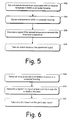
- FIG. 5 is a flow diagram that describes steps in a method in accordance with one embodiment.
- FIG. 6 is a flow diagram that describes steps in a method in accordance with one embodiment.
- the methods and systems sense an area proximate a ventilation structure of a computer and generate a signal if blockage of the ventilation structure occurs.
- the computing device can comprise any suitable computer, examples of which include, but are not limited to stationary personal computers, portable computers, cell phones, Palm Pilot brand computers and similar products, game or entertainment computers such as Game Boy brand computers, and the like.
- FIGS. 1-3 show an exemplary computer in accordance with one embodiment.
- the computer can comprise any suitable computer as described above.
- the computer comprises a notebook computer.
- Computer 100 comprises a housing 102 that defines an internal cavity 104 (FIG. 3) inside of which internal components of the computer are housed.
- the computer also includes a keyboard 106 and a display 108 .
- the computer's housing also includes a ventilation structure 110 .
- the ventilation structure is provided so that air can flow into and out of the internal cavity.
- Airflow is desirable for maintaining a temperature within the cavity that promotes normal computer operation. Specifically, without ventilation structure 110 , it is quite likely that the internal components of the computer might overheat due to heat generation issues that are typically associated with computer operation.
- FIG. 3 is a cross-section of the computer showing a portion of the internal cavity in a little more detail. Specifically shown is a CPU 112 , a cooling fan 114 , and a module 116 designated “components.” These “components” can comprise printed circuit boards, memory modules, and various other components that are typically provided within a computer's housing.
- a sensor 118 is also provided within the internal cavity. One purpose of the sensor is to sense conditions which could lead to a computer overheating. Accordingly, the sensor decreases the likelihood that the computer will overheat.
- Mounted on the housing is notification device 119 which is described further in FIG. 4 .
- the sensor 118 and notification device 119 can be components of a sensing/notification circuit 120 , which is described in FIG. 4 .
- FIG. 4 further illustrates one non-limiting embodiment of the sensing circuit.
- the sensing/notification circuit 120 is broken into two distinct structures, a sensing circuit and a notification circuit, which are functionally coupled. It is not essential to the embodiments described herein that all of these elements exist, or that these two circuits exist independently. Rather, one skilled in the art will readily see many other configurations which provide functional embodiments.
- the sensing/notification circuit can comprise the sensing circuit without a notification circuit element.
- some embodiments can have a sensor coupled to a notification circuit without a sensing circuit.
- sensors use a combination of applicable sensors and circuitry.
- Several types of sensors can be utilized in various embodiments. Exemplary non-limiting examples are photo-sensors 122 and thermo-sensors 124 .
- a photo-sensor 122 can be a component of the sensing/notification circuit 120 .
- the photo-sensor is mounted on the housing 102 and is positioned to sense light entering the internal cavity through the ventilation structure 110 .
- the sensing/notification circuit 120 is configured to generate a signal responsive to a condition that indicates that light is not entering the internal cavity in an amount that suggests that the ventilation structure is unblocked.
- the sensing circuit would sense ambient light entering through the ventilation structure. If a pillow fell against the ventilation structure it would cut off the light and the airflow into the internal cavity. The sensing circuit would then generate a signal which results in a user notification. The user, perceiving the notification, would remove the pillow, thus preventing overheating of the computer.
- the sensing/notification circuit can generate a signal which results in a notification being generated for the user.
- the purpose of the notification is to alert a user that blockage may be occurring.
- Exemplary non-limiting examples of user notification include a visual notification or an audio notification.
- a visual notification is displayed by the notification device 119 .
- the notification device can comprise an LED 130 which is mounted on the computer housing so that it is visible to a computer user.
- the LED can light-up or blink in any way that is likely to be noticed by the user.
- the signal/notification circuit can generate a display notification 132 that can appear on display 108 .
- the display notification can be similar to the rectangular information window which displays various important messages for the user. The notification can be superimposed over the current display window so that it is easily noticed.
- an audio notification can be produced on notification device 119 .
- notification device 119 comprises a speaker 134 , and an audio notification can be generated on the speaker. It is recognized that most computers have existing speakers and while a dedicated speaker is shown in the drawings for the purpose of illustration, it is not essential to the present embodiment. The system described will work equally well with any other speaker associated with the computer.
- a visual notification can be displayed on the computer display, and an audio notification created.
- the visual method should be adequate, but if the user is doing something else, the audio notification may get their attention.
- the computer can be shut down responsive to the signal being generated by the sensor.
- the shutdown can occur immediately, or alternatively, after the signal is generated for a definable period of time. The delay allows time for the user to correct the condition without having the computer shut down. Yet, if the user fails to correct the condition, the computer is protected.
- the means for shutting down the computer can be constructed using the components described in FIG. 4 .
- the computer shutdown can be achieved with controller 136 .
- the controller can be connected to the sensor 118 and the computer's power supply (not shown) so that if a signal is received from the sensor, the computer is shut down. If a delay in shutting down the computer is desired, timer circuit 138 can be connected to controller 136 so that the shutdown occurs only after a definable period of time. In another example, the same functional means can be achieved using logic circuit 140 .
- FIG. 4 Various components are described in FIG. 4 that can be used to shut down the computer if an overheating condition is detected by the sensor.
- FIG. 4 Various components are described in FIG. 4 that can be used to shut down the computer if an overheating condition is detected by the sensor.
- one skilled in the art will readily see other ways to carry out the present embodiment. For example, most computers already have a built-in time-keeping capability somewhere in the hardware or software. One skilled in the art could easily construct a delay means for shutting down the computer using the computer's existing time keeping capability.
- the sensing/notification circuit 120 comprises a thermo-sensor 124 which senses a temperature of the internal cavity. The sensing circuit generates a signal that can be used to keep the computer from overheating.
- thermo-sensor can be mounted inside the cavity and connected to an LED. If the thermo-sensor measures a temperature above the average recommended operating temperature for the computer, or any other threshold that might be set, the thermo-sensor can generate a signal which results in the LED being illuminated.
- the other notification mechanisms discussed above can be employed.
- FIG. 5 is a flow diagram that describes steps in a method in accordance with one described embodiment. The steps can be implemented by way of the exemplary computer of FIG. 3 operating in conjunction with the sensing/notification circuit of FIG. 4 . The method can also be practiced through the use of any other suitable hardware, software, firmware, or combination thereof.
- Step 502 sets a threshold temperature associated with a temperature within a computer housing.
- This temperature can be any temperature above which it is desirable to know the temperature has been exceeded.
- the temperature selected can be one above which the computer suffers from the possibility of shortened functional lifespan.
- the temperature can simply be the average operating temperature of the computer model selected.
- the temperature can be set by the computer manufacturer, a dealer setting up the computer and software, or a user. In some embodiments the adjustments can be made through the “Settings” and “Control Panel” screen displays.
- step 504 senses a temperature within the computer housing with a sensor 118 that is positioned on the housing.
- a sensor 118 Any appropriate type of sensor can be used with exemplary sensors described above.
- the sensor can be placed anywhere in the housing where it provides useful information
- Step 506 generates a signal if the sensed temperature exceeds the threshold temperature. Examples of signals and how they can be used are given above.
- step 508 takes an action based on the generated signal. This action can include shutting down the computer responsive to the signal, or shutting down the computer if the sensed temperature exceeds the threshold temperature for a definable period of time.
- FIG. 6 is a flow diagram that describes steps in the method in accordance with one embodiment. The method can be implemented with any appropriate combination of software and/or hardware.
- Step 602 senses an area proximate a ventilation structure in a computer housing. Sensing can be implemented through multiple different embodiments, as described above. For example, a photo-sensor 122 can be utilized by positioning it so that light entering the internal cavity through the ventilation structure can be sensed. Another example uses a thermo-sensor 124 positioned inside the internal cavity which senses the temperature of the internal cavity. In this example if an obstruction occurs the internal temperature sensed by the thermo-sensor will likely rise.
- Step 604 generates a signal if an object at least partially blocks the ventilation structure.
- Step 606 takes an action based on the generated signal.
- exemplary actions can include shutting the computer down responsive to the signal and shutting the computer down if the signal persists for a definable period of time.
Abstract
Description
Claims (14)
Priority Applications (1)
| Application Number | Priority Date | Filing Date | Title |
|---|---|---|---|
| US09/880,408 US6661655B2 (en) | 2001-06-13 | 2001-06-13 | Methods and systems for monitoring computers and for preventing overheating |
Applications Claiming Priority (1)
| Application Number | Priority Date | Filing Date | Title |
|---|---|---|---|
| US09/880,408 US6661655B2 (en) | 2001-06-13 | 2001-06-13 | Methods and systems for monitoring computers and for preventing overheating |
Publications (2)
| Publication Number | Publication Date |
|---|---|
| US20030002250A1 US20030002250A1 (en) | 2003-01-02 |
| US6661655B2 true US6661655B2 (en) | 2003-12-09 |
Family
ID=25376210
Family Applications (1)
| Application Number | Title | Priority Date | Filing Date |
|---|---|---|---|
| US09/880,408 Expired - Fee Related US6661655B2 (en) | 2001-06-13 | 2001-06-13 | Methods and systems for monitoring computers and for preventing overheating |
Country Status (1)
| Country | Link |
|---|---|
| US (1) | US6661655B2 (en) |
Cited By (13)
| Publication number | Priority date | Publication date | Assignee | Title |
|---|---|---|---|---|
| US20030218862A1 (en) * | 2002-05-24 | 2003-11-27 | International Business Machines Corporation | Temperature-controlled user interface |
| US6861943B2 (en) * | 2001-09-27 | 2005-03-01 | Alcatel Canada Inc. | System and method for network element equipment status monitoring |
| US20050068730A1 (en) * | 2003-09-29 | 2005-03-31 | Yao-Nan Lin | Heat dissipation method for microprocessors |
| US20060045168A1 (en) * | 2004-08-31 | 2006-03-02 | Pny Technologies, Inc. | Electronic module with built-in temperature display |
| US20060155424A1 (en) * | 2005-01-11 | 2006-07-13 | Takayuki Katoh | Thermal management of a personal computing apparatus |
| US20070094436A1 (en) * | 2005-10-20 | 2007-04-26 | Keown William F Jr | System and method for thermal management in PCI express system |
| US20070237636A1 (en) * | 2006-04-07 | 2007-10-11 | Sam Hsu | Computer cooling fan with display device |
| US20080055850A1 (en) * | 2006-06-01 | 2008-03-06 | Andrew Carlson | Data Center Air Circulation |
| US20090190625A1 (en) * | 2008-01-30 | 2009-07-30 | International Business Machines Corporation | Apparatus, system, and method for detecting fan rotation direction in electronic devices |
| US20100051243A1 (en) * | 2008-08-29 | 2010-03-04 | Apple Inc. | Methods and apparatus for cooling electronic devices using flow sensors |
| US8531386B1 (en) * | 2002-12-24 | 2013-09-10 | Apple Inc. | Computer light adjustment |
| CN103377108A (en) * | 2012-04-28 | 2013-10-30 | 鸿富锦精密工业(武汉)有限公司 | Abnormity warning system and method |
| US20160374572A1 (en) * | 2015-06-24 | 2016-12-29 | Casio Computer Co., Ltd. | Electronic apparatus, operation management method, and computer-readable medium |
Families Citing this family (7)
| Publication number | Priority date | Publication date | Assignee | Title |
|---|---|---|---|---|
| DE102004002447B4 (en) * | 2004-01-16 | 2005-11-24 | Fujitsu Siemens Computers Gmbh | Fan control circuit with overtemperature signaling, in particular for a power supply device |
| US7360945B2 (en) * | 2005-03-31 | 2008-04-22 | Intel Corporation | Apparatus for determining temperature of a portable computer system |
| US7563024B2 (en) * | 2006-09-28 | 2009-07-21 | Intel Corporation | Method and apparatus for measurement of electronics device skin temperature |
| US8374731B1 (en) * | 2008-12-24 | 2013-02-12 | Emc Corporation | Cooling system |
| CN105700954B (en) * | 2014-11-27 | 2019-02-22 | 英业达科技有限公司 | The mainboard control method of blade server |
| US11614782B2 (en) * | 2021-02-25 | 2023-03-28 | Dell Products L.P. | Fan blockage detection for an information handling system |
| WO2022260759A1 (en) * | 2021-06-08 | 2022-12-15 | Arris Enterprises Llc | Blocked vent sensor for electronic devices |
Citations (14)
| Publication number | Priority date | Publication date | Assignee | Title |
|---|---|---|---|---|
| US4585339A (en) * | 1983-11-28 | 1986-04-29 | Sharp Kabushiki Kaisha | Power control of electronic apparatus in response to surrounding brightness |
| US4864283A (en) * | 1986-06-30 | 1989-09-05 | Tandem Computers, Incorporated | Temperature alarm |
| US5115225A (en) * | 1990-11-13 | 1992-05-19 | Compaq Computer Corporation | Disk drive unit overheating warning system |
| US5590061A (en) * | 1994-05-12 | 1996-12-31 | Apple Computer, Inc. | Method and apparatus for thermal management in a computer system |
| RU2073906C1 (en) * | 1994-08-19 | 1997-02-20 | Александр Робертович Понурко | Device for on-line monitoring of heat modes of computer |
| JPH09284988A (en) * | 1996-04-18 | 1997-10-31 | Nec Gumma Ltd | Alarm device of personal computer |
| JPH1027039A (en) * | 1996-07-12 | 1998-01-27 | Kyushu Nippon Denki Software Kk | Cooling device for computer system |
| US5714938A (en) * | 1996-11-19 | 1998-02-03 | Cae Electronics Ltd. | Temperature protection device for air cooled electronics housing |
| US5764506A (en) * | 1994-01-31 | 1998-06-09 | Eynaud; Bruno | Method and apparatus for reducing the sound level of a microcomputer |
| US5835885A (en) * | 1997-06-05 | 1998-11-10 | Giga-Byte Technology Co., Ltd. | Over temperature protection method and device for a central processing unit |
| US6029251A (en) * | 1996-12-31 | 2000-02-22 | Opti Inc. | Method and apparatus for temperature sensing |
| US6082623A (en) * | 1999-03-04 | 2000-07-04 | Twinhead International Corp. | Cooling system and method for a portable computer |
| US6286109B1 (en) * | 1998-06-30 | 2001-09-04 | Digital Equipment Corporation | Method and apparatus for reducing heat generation in a portable computer |
| US6336080B1 (en) * | 1996-01-16 | 2002-01-01 | Compaq Computer Corporation | Thermal management of computers |
-
2001
- 2001-06-13 US US09/880,408 patent/US6661655B2/en not_active Expired - Fee Related
Patent Citations (14)
| Publication number | Priority date | Publication date | Assignee | Title |
|---|---|---|---|---|
| US4585339A (en) * | 1983-11-28 | 1986-04-29 | Sharp Kabushiki Kaisha | Power control of electronic apparatus in response to surrounding brightness |
| US4864283A (en) * | 1986-06-30 | 1989-09-05 | Tandem Computers, Incorporated | Temperature alarm |
| US5115225A (en) * | 1990-11-13 | 1992-05-19 | Compaq Computer Corporation | Disk drive unit overheating warning system |
| US5764506A (en) * | 1994-01-31 | 1998-06-09 | Eynaud; Bruno | Method and apparatus for reducing the sound level of a microcomputer |
| US5590061A (en) * | 1994-05-12 | 1996-12-31 | Apple Computer, Inc. | Method and apparatus for thermal management in a computer system |
| RU2073906C1 (en) * | 1994-08-19 | 1997-02-20 | Александр Робертович Понурко | Device for on-line monitoring of heat modes of computer |
| US6336080B1 (en) * | 1996-01-16 | 2002-01-01 | Compaq Computer Corporation | Thermal management of computers |
| JPH09284988A (en) * | 1996-04-18 | 1997-10-31 | Nec Gumma Ltd | Alarm device of personal computer |
| JPH1027039A (en) * | 1996-07-12 | 1998-01-27 | Kyushu Nippon Denki Software Kk | Cooling device for computer system |
| US5714938A (en) * | 1996-11-19 | 1998-02-03 | Cae Electronics Ltd. | Temperature protection device for air cooled electronics housing |
| US6029251A (en) * | 1996-12-31 | 2000-02-22 | Opti Inc. | Method and apparatus for temperature sensing |
| US5835885A (en) * | 1997-06-05 | 1998-11-10 | Giga-Byte Technology Co., Ltd. | Over temperature protection method and device for a central processing unit |
| US6286109B1 (en) * | 1998-06-30 | 2001-09-04 | Digital Equipment Corporation | Method and apparatus for reducing heat generation in a portable computer |
| US6082623A (en) * | 1999-03-04 | 2000-07-04 | Twinhead International Corp. | Cooling system and method for a portable computer |
Cited By (27)
| Publication number | Priority date | Publication date | Assignee | Title |
|---|---|---|---|---|
| US6861943B2 (en) * | 2001-09-27 | 2005-03-01 | Alcatel Canada Inc. | System and method for network element equipment status monitoring |
| US20030218862A1 (en) * | 2002-05-24 | 2003-11-27 | International Business Machines Corporation | Temperature-controlled user interface |
| US6909602B2 (en) * | 2002-05-24 | 2005-06-21 | International Business Machines Corporation | Temperature-controlled user interface |
| US8531386B1 (en) * | 2002-12-24 | 2013-09-10 | Apple Inc. | Computer light adjustment |
| US8970471B2 (en) * | 2002-12-24 | 2015-03-03 | Apple Inc. | Computer light adjustment |
| US9788392B2 (en) | 2002-12-24 | 2017-10-10 | Apple Inc. | Computer light adjustment |
| US20050068730A1 (en) * | 2003-09-29 | 2005-03-31 | Yao-Nan Lin | Heat dissipation method for microprocessors |
| US20060045168A1 (en) * | 2004-08-31 | 2006-03-02 | Pny Technologies, Inc. | Electronic module with built-in temperature display |
| US7131767B2 (en) * | 2004-08-31 | 2006-11-07 | Pny Technologies, Inc. | Electronic module with built-in temperature display |
| US20080059004A1 (en) * | 2005-01-11 | 2008-03-06 | Lenovo(Singapore) Pte Ltd. | Thermal Management Of A Personal Computing Apparatus |
| US7412306B2 (en) * | 2005-01-11 | 2008-08-12 | Lenovo (Singapore) Pte. Ltd. | Thermal management of a personal computing apparatus |
| US20060155424A1 (en) * | 2005-01-11 | 2006-07-13 | Takayuki Katoh | Thermal management of a personal computing apparatus |
| US8031466B2 (en) | 2005-01-11 | 2011-10-04 | Lenovo (Singapore) Pte Ltd. | Thermal management of a personal computing apparatus |
| US20070094436A1 (en) * | 2005-10-20 | 2007-04-26 | Keown William F Jr | System and method for thermal management in PCI express system |
| CN1959662B (en) * | 2005-10-20 | 2010-05-12 | 联想(新加坡)私人有限公司 | Computer, method for operating computer and computer system |
| US20070237636A1 (en) * | 2006-04-07 | 2007-10-11 | Sam Hsu | Computer cooling fan with display device |
| US20080055850A1 (en) * | 2006-06-01 | 2008-03-06 | Andrew Carlson | Data Center Air Circulation |
| US8636565B2 (en) * | 2006-06-01 | 2014-01-28 | Exaflop Llc | Data center air circulation |
| US20090190625A1 (en) * | 2008-01-30 | 2009-07-30 | International Business Machines Corporation | Apparatus, system, and method for detecting fan rotation direction in electronic devices |
| US7698095B2 (en) | 2008-01-30 | 2010-04-13 | International Business Machines Corporation | Apparatus, system, and method for detecting fan rotation direction in electronic devices |
| US8695690B2 (en) * | 2008-08-29 | 2014-04-15 | Apple Inc. | Methods for cooling electronic devices using flow sensors |
| US20100051243A1 (en) * | 2008-08-29 | 2010-03-04 | Apple Inc. | Methods and apparatus for cooling electronic devices using flow sensors |
| US9904334B2 (en) | 2008-08-29 | 2018-02-27 | Apple Inc. | Cooling electronic devices using flow sensors |
| US20130285817A1 (en) * | 2012-04-28 | 2013-10-31 | Hon Hai Precision Industry Co., Ltd. | Customizable alarm sytem and method for computer |
| CN103377108A (en) * | 2012-04-28 | 2013-10-30 | 鸿富锦精密工业(武汉)有限公司 | Abnormity warning system and method |
| US20160374572A1 (en) * | 2015-06-24 | 2016-12-29 | Casio Computer Co., Ltd. | Electronic apparatus, operation management method, and computer-readable medium |
| US9854983B2 (en) * | 2015-06-24 | 2018-01-02 | Casio Computer Co., Ltd. | Electronic apparatus and operation management method utilizing temperature information to suppress temperature effects caused by apparatus in contact with skin |
Also Published As
| Publication number | Publication date |
|---|---|
| US20030002250A1 (en) | 2003-01-02 |
Similar Documents
| Publication | Publication Date | Title |
|---|---|---|
| US6661655B2 (en) | Methods and systems for monitoring computers and for preventing overheating | |
| US5714938A (en) | Temperature protection device for air cooled electronics housing | |
| US7271561B2 (en) | Fan module and control device thereof | |
| US20090116189A1 (en) | Cooling System for a Computer Power Supply Unit | |
| US10665528B2 (en) | Water-cooling thermal dissipating system and thermal dissipating method | |
| TW201426271A (en) | Method for providing over-temperature protection of a target device, apparatus for providing over-temperature protection, and information processing system thereof | |
| JP2008305568A (en) | High-pressure discharge lamp lighting device, light source device, and its control method | |
| CN108628362A (en) | A kind of power control cabinet and its heat dissipating method, radiator | |
| US20050201056A1 (en) | Heat-dissipating device for a computer casing | |
| CN205812278U (en) | A kind of DTV STB automaton | |
| CN102123574A (en) | Electronic device and method for detecting radiator fan of electronic device | |
| US7458781B2 (en) | Radiation fan driving apparatus | |
| TW201339787A (en) | Communication terminal and control method thereof | |
| JP2009217776A (en) | Information processor | |
| US10514736B2 (en) | Method and computer system for reducing noise from cooling fan | |
| CN2519947Y (en) | Overheat protector for computer | |
| US11348860B2 (en) | Water-cooling thermal dissipating method | |
| CN101340801A (en) | Heat radiating device of power supply apparatus | |
| CN2526891Y (en) | Remote-controlled computer casing with temp controlling and auto-cooling | |
| CN205378142U (en) | STB with multi -functional protection | |
| TWM467104U (en) | Overheat protecting device and electrical device with overheat protecting function | |
| JP3789436B2 (en) | Fan-type air cooling device and drive control method thereof | |
| JP2006214638A (en) | Dc fan motor control device of air conditioner | |
| CN216083603U (en) | Server | |
| CN219197668U (en) | PWM automatic temperature control speed regulation radiator fan |
Legal Events
| Date | Code | Title | Description |
|---|---|---|---|
| AS | Assignment |
Owner name: HEWLETT-PACKARD COMPANY, COLORADO Free format text: ASSIGNMENT OF ASSIGNORS INTEREST;ASSIGNOR:YIN, MEMPHIS ZHIHONG;REEL/FRAME:012633/0927 Effective date: 20010606 |
|
| AS | Assignment |
Owner name: HEWLETT-PACKARD DEVELOPMENT COMPANY L.P., TEXAS Free format text: ASSIGNMENT OF ASSIGNORS INTEREST;ASSIGNOR:HEWLETT-PACKARD COMPANY;REEL/FRAME:014061/0492 Effective date: 20030926 Owner name: HEWLETT-PACKARD DEVELOPMENT COMPANY L.P.,TEXAS Free format text: ASSIGNMENT OF ASSIGNORS INTEREST;ASSIGNOR:HEWLETT-PACKARD COMPANY;REEL/FRAME:014061/0492 Effective date: 20030926 |
|
| FPAY | Fee payment |
Year of fee payment: 4 |
|
| FPAY | Fee payment |
Year of fee payment: 8 |
|
| REMI | Maintenance fee reminder mailed | ||
| LAPS | Lapse for failure to pay maintenance fees | ||
| STCH | Information on status: patent discontinuation |
Free format text: PATENT EXPIRED DUE TO NONPAYMENT OF MAINTENANCE FEES UNDER 37 CFR 1.362 |
|
| FP | Lapsed due to failure to pay maintenance fee |
Effective date: 20151209 |