US666100A - Motor for propelling boats. - Google Patents
Motor for propelling boats. Download PDFInfo
- Publication number
- US666100A US666100A US3015800A US1900030158A US666100A US 666100 A US666100 A US 666100A US 3015800 A US3015800 A US 3015800A US 1900030158 A US1900030158 A US 1900030158A US 666100 A US666100 A US 666100A
- Authority
- US
- United States
- Prior art keywords
- boat
- walking
- beams
- motor
- treadles
- Prior art date
- Legal status (The legal status is an assumption and is not a legal conclusion. Google has not performed a legal analysis and makes no representation as to the accuracy of the status listed.)
- Expired - Lifetime
Links
Images

Classifications
-
- B—PERFORMING OPERATIONS; TRANSPORTING
- B63—SHIPS OR OTHER WATERBORNE VESSELS; RELATED EQUIPMENT
- B63H—MARINE PROPULSION OR STEERING
- B63H16/00—Marine propulsion by muscle power
- B63H16/08—Other apparatus for converting muscle power into propulsive effort
- B63H16/12—Other apparatus for converting muscle power into propulsive effort using hand levers, cranks, pedals, or the like, e.g. water cycles, boats propelled by boat-mounted pedal cycles
- B63H16/14—Other apparatus for converting muscle power into propulsive effort using hand levers, cranks, pedals, or the like, e.g. water cycles, boats propelled by boat-mounted pedal cycles for propelled drive
Definitions
- My invention relates to an improved motor for propelling boats; and the main object is to provide a motor which can be easily attached to or detached from boats without altering or damaging the same.
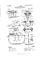
- FIG. 1 is a longitudinal section through a boat equipped with my improved motor.
- Fig. 2 is an enlarged fragmentary view of a portion of a boat having my improved motor attached thereto.
- Fig.3 is a vertical transverse section on line a a, Fig. 2.
- Fig. 4 is an enlarged top view of the upper fastening device.
- Fig. 5 is an enlarged top view of the lower fastening device.
- Fig. 6 is an enlarged fragmentary View of the walking-beams and.
- Fig. 7 is an enlarged fragmentary top view of a portionof a boat with the walking-beams and their supporting-fulcrum attached thereto.
- Fig. 8 is a fragmentary longitudinal section through a boat, showing an enlarged side view of the treadles and their supporting slide-rods.
- Fig. 9 is a fragmentary transverse section through a boat, showing the treadles and their supporting-rods.
- Fig. 10 is an enlarged detached top View of one of the treadles.
- Fig. 11 is a detached side view of one of the treadles looking in the direction of the arrow V, Fig. 10.
- Fig. 12 is an enlarged detached side view of the forked support and the pulleys.
- Fig. 13 is a transverse section through a boat to illustrate a modified form of treadle and support.
- Fig. 14: is an enlarged detached view of one of the pawls, its spring, and a fragment of the crank-arm to which it is pivoted.
- the motor-frame consists of two plates 1 and 2, which are separated from each other sufficiently to support the operating gearwheels between them.
- a strengthening-rod 3 passes through the lower portion of the plates and a propeller-shaft 4 is journaled in the plates above this rod and has a propellerwheel 5 mounted on its rear end which projects behind the rear plate 2.
- Astrengthening-shaft 6 is mounted in the plates above the propeller-shaft and maintains the npperportion of the plates in their relative position.
- a gear-wheel 7 is rotatably mountedon the shaft 6 and meshes with a gear-Wheel 8, rigidly mounted on the propeller shaft.
- a ratchet-wheel 9 is rigidly attached to each side of the gear-wheel '7, and two crank-arms 10 and 11, each of which is provided with an opening at one end through which the shaft 6 passes, are arranged on opposite sides of the gear-wheel 7.
- a pawl 12 is pivoted in each crank-arm and engages the teeth of the adjacent ratchet-wheel, being held in position by the spring 13.
- Two rods 14: and 15, which form walking-beams, are pivoted to a fulcrum, and blocks 16 are pivoted to the rear ends of these Walking-beams.
- a connectingrod 17 connects each one of these blocks to the upperend of one of the crank-arms.
- the blocks are preferably slotted at their ends, and the ends of the walking-beams and the connecting-rods are placed in these slots and secured in place by the bolts 18 and 19.
- the fulcrum preferably consists of a base 20, which is bolted to the boat by the bolts 21, a vertical support 22, extending from the base, and a horizontal rod 23, extending through the upper end of the vertical support upon which the walking-beams are pivoted.
- the walking-beams are arranged on opposite sides of the support 22 and are held in place against the support by the nuts or washers 24. (See Fig.
- the rod 23 is longer than the distance between the walking-beams and pro- 35 downward and forward, substantially as 40 the walking-beams by flexible cords 36, which 45 each composes two parallel plates 37, slightly jects outwardly from each side to form supports 25 for springs 26, which maintain the forward ends of the walking-beams in an ele- Vated position and return them to said ele- 5 Vated position immediately upon the release of thedownward-pullingpower.
- Thesesprings 26 are preferably formed as shown in Figs. 6 and 7, having a straight portion at each end and an intermediate coiled portion which is 10 around one of the supports 25. One of the ends of each spring is fastened to the base 20 and the other to the walking-beam in front of its pivoting-point.
- One of the walking-beams is longer than the other and projects rearward a short distance'farther, the object being to vertically arrange the rear end of each walking-beam. vertically above the crank-arm to which it is connected.
- a vertical standard 27 is mounted in a base 28, which is secured to the bottom of the boat, substantially vertically below the forward ends of the walking-beams, by the bolts 29.
- the standard 27 is provided with a forked up per end 30, and two pulleys 31 are mounted upon ahorizontal shaft 32, which is journaled' in the forks 30. (See Fig. 12.)
- Two substantially parallel bars or rods 33, of metal, are secured to the boat-bottom in front of the 0 standard 27, and a seat 34 is placed in the boat between these bars or rods and the standard.
- Each of the bars or rods is bolted at its rear end to the boat by the bolt 35 and extends vertically upward and then diagonally 43, having forks 44, which embrace the boatstern and are fastened thereto by the screws or bolts 45.
- the lower fastening is in the form of a curved bar having a screwthreaded rear end 46, which passes through the lower portion of the plate 1 andis locked in place by a lock-nut 47.
- the forward end of the bar has an enlarged forked portion which embraces the boat-stern and is fastened thereto by screws or bolts 48. It is obvious that these forked portions may be shaped for attachment to boats having sterns of various different forms, and I therefore do not limit myself to the shape shown.
- a rudder 49 is supported upon a vertical 8o rod 50, which bends horizontally forward to form a horizontal portion 51, the forward end of which passes through the rear plate 2, being locked in place by the nut 52, the horizontal portion 51 being of sufficient length to 8 5 bring the rudder in the rear of the propeller. (See Fig. 2.)
- a bar 53 is placed transversely across the boat with a lug 54 at each end, which extends downwardly on the exterior of the gunwales and serves to prevent movement of the bar transversely to the boat, and treadle-arms 55 are pivoted to said bar and extend downwardly therefrom and bend at their lower ends to form 9 5 treadles 56, the cords connected to the walking-beams being fastened to the arms.
- the motor can be detached from the boat in two ways, either by removing the nuts 42 and 47 or by detaching the forked fastenings from the boat-stern.
- a boat having a propeller and its support detachably secured to its stern, walkingbeams supported from the boat, connections between the rear ends of the walking-beams n 5 and the propeller, foot-treadles in the boat and connections between the foot -treadles shown in Figs. 1 and 8.
- a treadle device is mounted on the diagonally-extending portions of each of these rods, so as to slide thereon, and is connected to the forward ends of are fastened at the ends to the walking-beam and treadles,.respectively, and extend under the pulleys. These treadles are formed substantially as shown in Figs. 10 and 11, and
- a boat having a motor attached thereto which is passed through the plate 1 and fasand comprising a frame, a shaft journaled in tened in place by the screw-nut 42.
- This bar said frame and carrying a propeller, walking- 65 isprovided with an enlarged forward portion beams, ratchet mechanism geared to the i propeller-shaft, crank-arms connecting the ratchet mechanism to the walking beams, and treadles connected to the walking-beams.
- a boat having a motor attached thereto and comprising a frame, a shaft journaled in said frame and carrying a propeller, walkingbeams, mechanism connecting the propellershaft to the Walking-beams, treadles connecting to the Walking-beams, a rod extending rearward from the frame and bending downward and a rudder arranged on said rod in the rear of the propeller.
- a boat provided with a motor having a portion of its mechanism arranged in the rear of said boat, foot-treadles in the boat-bottom and walking-beams connecting the treadles to the motor; one of said Walking-beams being longer than the other.
- a boat having a motor comprising a propeller, walking-beams operatively connected to said propeller, a standard secured in the boat and having a forked upper end, pulleys supported on said fork, treadles and cords connecting the walking-beams to the treadles, and passing under the pulleys, substantially as set forth.
Description
No. 666,l00. Patented Ian. l5, l90l.
. J. F. KEBNS.
MOTOR. FOB'PROPELLING BOATS.
(Appfication filed Sept. 15, 1900.)
2 Sheets-Shaet I.
(No Model.)
Inventor. r /(W.
Witnesses.
VW M W NORRIS vzrzns cu morouma. wnsmumou u c 0 B m n a I. v 8 t n e t a P S T A 0 B G m NL nnL n 0 3 F 8 0 F B 0 T a M 6 6 6 0 Y (Application filed Sept. 16, 1900.)
2 Shoots-Sheet 2.
Inventor.
Witnesse.
m m m 4 0.. PHOTOAJTHO WASHINGTON D c.
NITED STATES PAT T OFFICE.
MOTOR FOR PROPELLING BOATS.
fiPEGIFICATION formingpart of Letters Patent N 0. 666,100, dated January 15, 1901. A li ti fil d September 15, 1900- Serial No. 30,158. (No model.)
To all whom it may concern:
Be it known that I, JOHN F. KERNS, a citizen of the United States, residing at Bufialo, in the county of Erie and State of New York, have invented certain new and useful Improvements in Motors for Propelling Boats, of which the following is a specification.
My invention relates to an improved motor for propelling boats; and the main object is to provide a motor which can be easily attached to or detached from boats without altering or damaging the same.
It also relates to a novel form of steeringgear and to certain details of construction, all of which will be fully and clearly hereinafter described and claimed.
For a full understanding of the merits and advantages of the invention reference is to be had to the accompanying drawings and the following description.
The invention is susceptible to various changes in the form, proportion, and minor details of construction Without departing from the principle or sacrificing any of the advantages thereof, and to a full disclosure of the invention an adaptation thereof is shown in the accompanying drawings, in which Figure 1 is a longitudinal section through a boat equipped with my improved motor. Fig. 2 is an enlarged fragmentary view of a portion of a boat having my improved motor attached thereto. Fig.3 is a vertical transverse section on line a a, Fig. 2. Fig. 4 is an enlarged top view of the upper fastening device. Fig. 5 is an enlarged top view of the lower fastening device. Fig. 6 is an enlarged fragmentary View of the walking-beams and.
their supporting-fulcrum. Fig. 7 is an enlarged fragmentary top view of a portionof a boat with the walking-beams and their supporting-fulcrum attached thereto. Fig. 8 is a fragmentary longitudinal section through a boat, showing an enlarged side view of the treadles and their supporting slide-rods. Fig. 9 is a fragmentary transverse section through a boat, showing the treadles and their supporting-rods. Fig. 10 is an enlarged detached top View of one of the treadles. Fig. 11 is a detached side view of one of the treadles looking in the direction of the arrow V, Fig. 10. Fig. 12 is an enlarged detached side view of the forked support and the pulleys. Fig. 13 is a transverse section through a boat to illustrate a modified form of treadle and support. Fig. 14: is an enlarged detached view of one of the pawls, its spring, and a fragment of the crank-arm to which it is pivoted.
In referring to the drawings in detail like numerals designate like parts.
The motor-frame consists of two plates 1 and 2, which are separated from each other sufficiently to support the operating gearwheels between them. A strengthening-rod 3 passes through the lower portion of the plates and a propeller-shaft 4 is journaled in the plates above this rod and has a propellerwheel 5 mounted on its rear end which projects behind the rear plate 2. Astrengthening-shaft 6 is mounted in the plates above the propeller-shaft and maintains the npperportion of the plates in their relative position. A gear-wheel 7 is rotatably mountedon the shaft 6 and meshes with a gear-Wheel 8, rigidly mounted on the propeller shaft. A ratchet-wheel 9 is rigidly attached to each side of the gear-wheel '7, and two crank- arms 10 and 11, each of which is provided with an opening at one end through which the shaft 6 passes, are arranged on opposite sides of the gear-wheel 7. A pawl 12 is pivoted in each crank-arm and engages the teeth of the adjacent ratchet-wheel, being held in position by the spring 13. Two rods 14: and 15, which form walking-beams, are pivoted to a fulcrum, and blocks 16 are pivoted to the rear ends of these Walking-beams. A connectingrod 17 connects each one of these blocks to the upperend of one of the crank-arms. The blocks are preferably slotted at their ends, and the ends of the walking-beams and the connecting-rods are placed in these slots and secured in place by the bolts 18 and 19. The fulcrum preferably consists of a base 20, which is bolted to the boat by the bolts 21, a vertical support 22, extending from the base, and a horizontal rod 23, extending through the upper end of the vertical support upon which the walking-beams are pivoted. The walking-beams are arranged on opposite sides of the support 22 and are held in place against the support by the nuts or washers 24. (See Fig. 7.) The rod 23 is longer than the distance between the walking-beams and pro- 35 downward and forward, substantially as 40 the walking-beams by flexible cords 36, which 45 each composes two parallel plates 37, slightly jects outwardly from each side to form supports 25 for springs 26, which maintain the forward ends of the walking-beams in an ele- Vated position and return them to said ele- 5 Vated position immediately upon the release of thedownward-pullingpower. Thesesprings 26 are preferably formed as shown in Figs. 6 and 7, having a straight portion at each end and an intermediate coiled portion which is 10 around one of the supports 25. One of the ends of each spring is fastened to the base 20 and the other to the walking-beam in front of its pivoting-point.
One of the walking-beams is longer than the other and projects rearward a short distance'farther, the object being to vertically arrange the rear end of each walking-beam. vertically above the crank-arm to which it is connected.
A vertical standard 27 is mounted in a base 28, which is secured to the bottom of the boat, substantially vertically below the forward ends of the walking-beams, by the bolts 29. The standard 27 is provided with a forked up per end 30, and two pulleys 31 are mounted upon ahorizontal shaft 32, which is journaled' in the forks 30. (See Fig. 12.) Two substantially parallel bars or rods 33, of metal, are secured to the boat-bottom in front of the 0 standard 27, and a seat 34 is placed in the boat between these bars or rods and the standard. Each of the bars or rods is bolted at its rear end to the boat by the bolt 35 and extends vertically upward and then diagonally 43, having forks 44, which embrace the boatstern and are fastened thereto by the screws or bolts 45. The lower fastening is in the form of a curved bar having a screwthreaded rear end 46, which passes through the lower portion of the plate 1 andis locked in place by a lock-nut 47. The forward end of the bar has an enlarged forked portion which embraces the boat-stern and is fastened thereto by screws or bolts 48. It is obvious that these forked portions may be shaped for attachment to boats having sterns of various different forms, and I therefore do not limit myself to the shape shown.
A rudder 49 is supported upon a vertical 8o rod 50, which bends horizontally forward to form a horizontal portion 51, the forward end of which passes through the rear plate 2, being locked in place by the nut 52, the horizontal portion 51 being of sufficient length to 8 5 bring the rudder in the rear of the propeller. (See Fig. 2.)
In the modification shown in Fig. 13 a bar 53 is placed transversely across the boat with a lug 54 at each end, which extends downwardly on the exterior of the gunwales and serves to prevent movement of the bar transversely to the boat, and treadle-arms 55 are pivoted to said bar and extend downwardly therefrom and bend at their lower ends to form 9 5 treadles 56, the cords connected to the walking-beams being fastened to the arms.
The motor can be detached from the boat in two ways, either by removing the nuts 42 and 47 or by detaching the forked fastenings from the boat-stern.
In operating the motor the operator sits upon the seat, places his feet upon the treadles, and presses them. alternately forward. This gives an alternating movement to the walking-beams and rotates the propeller by means of the crank-arms.
In the modification the treadles are operated alternately and swing back and forth on the bar 53. v V
I claim as my invention- 1. A boat having a propeller and its support detachably secured to its stern, walkingbeams supported from the boat, connections between the rear ends of the walking-beams n 5 and the propeller, foot-treadles in the boat and connections between the foot -treadles shown in Figs. 1 and 8. A treadle device is mounted on the diagonally-extending portions of each of these rods, so as to slide thereon, and is connected to the forward ends of are fastened at the ends to the walking-beam and treadles,.respectively, and extend under the pulleys. These treadles are formed substantially as shown in Figs. 10 and 11, and
separated from each other, between which two rows of rollers 38 are mounted, the space between the rollers being slightly greater than the width of the bars or rods 33 to permit the 50 treadle to slide easily thereon, a roughened surfaced foot portion 39 projecting outwardly from these plates,'on which the foot of the operator is adapted to be placed, and an ear and the forward ends of the walking-beams. or lug 4O projecting inwardly, to which the 2. A boat having a motor attached thereto, 55 cords 36 are attached. and comprising a frame, a shaft journaled in The rear portion of the motor, comprising said frame and carrying a propeller, a secthe propeller, its gears, and support, are atondary shaft journaled in the frame, intertached to the stern of the boat by clamps or meshing gears connecting said shafts, walksimilar easily attached and detached fastening-beams, mechanism connecting the second- 60 ings. The preferred form of these fastenings ary shaft to the walking-beams, and treadles r2 5 is shown in Figs. 2, 4, and 5. The upper connected to the walking-beams. fastening is in the form of a screw- bar 41, 3. A boat having a motor attached thereto, which is passed through the plate 1 and fasand comprising a frame, a shaft journaled in tened in place by the screw-nut 42. This bar said frame and carrying a propeller, walking- 65 isprovided with an enlarged forward portion beams, ratchet mechanism geared to the i propeller-shaft, crank-arms connecting the ratchet mechanism to the walking beams, and treadles connected to the walking-beams.
4. A boat having a motor attached thereto and comprising a frame, a shaft journaled in said frame and carrying a propeller, walkingbeams, mechanism connecting the propellershaft to the Walking-beams, treadles connecting to the Walking-beams, a rod extending rearward from the frame and bending downward and a rudder arranged on said rod in the rear of the propeller.
5. A boat provided with a motor having a portion of its mechanism arranged in the rear of said boat, foot-treadles in the boat-bottom and walking-beams connecting the treadles to the motor; one of said Walking-beams being longer than the other.
6. The combination with a boat, of a mofor having a portion of its mechanism hung from the rear of said boat and comprising a frame, a propeller-shaft journaled in said frame, a propeller on said shaft, a stationary shaft in said frame above the propeller-shaft, a gear-Wlfeel mounted on the propeller-shaft,
a gear-Wheel journaled on the stationary shaft and meshing with the gear-Wheel on the propeller-shaft, a ratchet-wheel on each side of the gear-wheel on the stationary shaft, crank-arms pivotally mounted on the stationary shaft, pawls on the crank-arms engaging With the ratchet-wheels, Walkingbeams fulcrumed on the boat, rods connecting the crank-arms to the walking-beams,
slide-rods in the boat, treadles on said rods and cords connecting the treadles to the walking-heams, as set forth.
7. The combination With a boat, of a motor comprising a frame adapted to be secured to the boat-stern, a propeller and shaft journaled in said frame, walking-beams of unequal length fulcrnmed in the boat, connections between the walkingbeams and the propeller-shaft, foot-treadles and connections between the walking-beams and foot-treadles.
8. The combination of a boat, of a motor having a frame, rods detachably secured to the motorframe and extending forwardly therefrom and having forks at their forward ends adapted to embrace and be secured to the boat-stern, whereby the motor can be removed from the boat by either detaching the forks from the boat-stern or the rods from the frame of the motor, substantially as set forth.
9. A boat having a motor comprising a propeller, walking-beams operatively connected to said propeller, a standard secured in the boat and having a forked upper end, pulleys supported on said fork, treadles and cords connecting the walking-beams to the treadles, and passing under the pulleys, substantially as set forth.
JOHN F. KERNS.
Priority Applications (1)
| Application Number | Priority Date | Filing Date | Title |
|---|---|---|---|
| US3015800A US666100A (en) | 1900-09-15 | 1900-09-15 | Motor for propelling boats. |
Applications Claiming Priority (1)
| Application Number | Priority Date | Filing Date | Title |
|---|---|---|---|
| US3015800A US666100A (en) | 1900-09-15 | 1900-09-15 | Motor for propelling boats. |
Publications (1)
| Publication Number | Publication Date |
|---|---|
| US666100A true US666100A (en) | 1901-01-15 |
Family
ID=2734656
Family Applications (1)
| Application Number | Title | Priority Date | Filing Date |
|---|---|---|---|
| US3015800A Expired - Lifetime US666100A (en) | 1900-09-15 | 1900-09-15 | Motor for propelling boats. |
Country Status (1)
| Country | Link |
|---|---|
| US (1) | US666100A (en) |
-
1900
- 1900-09-15 US US3015800A patent/US666100A/en not_active Expired - Lifetime
Similar Documents
| Publication | Publication Date | Title |
|---|---|---|
| US666100A (en) | Motor for propelling boats. | |
| US515682A (en) | Means for propelling boats | |
| US637547A (en) | Marine velocipede. | |
| US621465A (en) | Bicycle-boat | |
| US573522A (en) | Propelling mechanism for boats | |
| US428213A (en) | Benjamin jarrell | |
| US529717A (en) | Percy james deacon | |
| US521405A (en) | Propelling mechanism for boats | |
| US618555A (en) | Propulsion mechanism for boats | |
| US1071709A (en) | Water-cycle. | |
| US583762A (en) | Propeller for boats | |
| US233919A (en) | ooloney | |
| US540680A (en) | Marine velocipede | |
| US586851A (en) | Water-bicycle | |
| US381729A (en) | tibbles | |
| US504685A (en) | Robert steel | |
| US408745A (en) | Tricycle | |
| US568499A (en) | Propeller for boats | |
| US424026A (en) | Boat-propelling mechanism | |
| US1189618A (en) | Manually-operated screw-propeller. | |
| US481113A (en) | Half to joseph | |
| US280299A (en) | Joseph l | |
| US453092A (en) | Tram-engine | |
| US645807A (en) | Boat-propeller. | |
| US678275A (en) | Propeller. |