US665222A - Air-compressing machine. - Google Patents
Air-compressing machine. Download PDFInfo
- Publication number
- US665222A US665222A US2637500A US1900026375A US665222A US 665222 A US665222 A US 665222A US 2637500 A US2637500 A US 2637500A US 1900026375 A US1900026375 A US 1900026375A US 665222 A US665222 A US 665222A
- Authority
- US
- United States
- Prior art keywords
- cylinders
- rods
- air
- heads
- cross
- Prior art date
- Legal status (The legal status is an assumption and is not a legal conclusion. Google has not performed a legal analysis and makes no representation as to the accuracy of the status listed.)
- Expired - Lifetime
Links
- 230000007246 mechanism Effects 0.000 description 6
- 230000008878 coupling Effects 0.000 description 5
- 238000010168 coupling process Methods 0.000 description 5
- 238000005859 coupling reaction Methods 0.000 description 5
- 210000000038 chest Anatomy 0.000 description 2
- 238000010276 construction Methods 0.000 description 2
- 230000003292 diminished effect Effects 0.000 description 1
- 230000009191 jumping Effects 0.000 description 1
- 230000002093 peripheral effect Effects 0.000 description 1
Images

Classifications
-
- F—MECHANICAL ENGINEERING; LIGHTING; HEATING; WEAPONS; BLASTING
- F04—POSITIVE - DISPLACEMENT MACHINES FOR LIQUIDS; PUMPS FOR LIQUIDS OR ELASTIC FLUIDS
- F04B—POSITIVE-DISPLACEMENT MACHINES FOR LIQUIDS; PUMPS
- F04B27/00—Multi-cylinder pumps specially adapted for elastic fluids and characterised by number or arrangement of cylinders
- F04B27/02—Multi-cylinder pumps specially adapted for elastic fluids and characterised by number or arrangement of cylinders having cylinders arranged oppositely relative to main shaft
Definitions
- My invention seeks to provide a simple and inexpensive means for storing up air under pressure, which means can be conveniently operated either 'by manual or mechanical power, and the same comprehends'generally a base constructed to receive a series of compressingcylinders, means for detachably mounting the said cylinders and for coupling up the several cylinders,'whereby any desired number may be set into a cooperative condition and any one of the set removed without disorganizing the remaining cylinders, and means being also included for coupling the cylinders together and joining their operating-pistons.
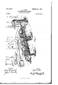
- FIG. 1 is a perspective view of my improved air-compressing mechanism, the same including three cylinders.
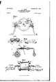
- Fig. 2 is a plan view of the same with but two cylinders coupled up.
- Fig. 3 is a similar view of the con: struction shown in Fig. 2, the two cylinders being illustrated in horizontal section, the line of section through one of the cylinders being taken through the valve-chests thereof to the more clearly illustrate the arrangement of the puppet-valves.
- Fig. 4 is a transverse section on the line 4 4 of Fig. 3.
- Fig. 5 is a detail section illustrating means for detachably securing the bearing-box of the crossheads.
- Fig. 6 is a detail view illustrating the manner of joining the end of one of thepiston-rods 9 with the cross member 10.
- Fig. 7 is a detail view showing the valved pipe connection joining one of the valve holding chambers with the main offtake-pipe,and
- Fig. 8 is a detail side elevation of one of the cylinders hereinafter referred to.
- my improved air-compressingmechanism embodies a suitable base-frame having end portions 1 1 and sides 2 2, the said sides and end members being braced by askeleton bottom 3, as clearly shown in Fig. 3.
- the sides 2 at the top of the bed each have sockets or recesses 2 2, arranged in oppositelydisposed sets.
- One set of recesses 2 is provided for a single compressing-cylinder, and the said recesses are so arranged that the said cylinders may be conveniently placed in position and held secure Without the use of bolts, nuts, &c., the said manner of seating the cylinders in proper operative position being also aided by the peculiar cooperative arrangement of the several cylinders and their piston-rods, as will hereinafter be more fully described.
- Fig. 1 of the drawings I have illustrated the base or supporting frame as provided with three sets of recesses to receive a corresponding number of cylinders; but'I desire it understood the said base may be equipped with a greater or less number of said recesses.
- the diameter of the end plates of the cylinders 4 is greater than the space between the sides 2, whereby to provide for quickly seating the cylinders upon the base, and to facilitate such quick adjustment of the cylinders the recesses 2 are spaced to receive the peripheral flanges 4*. of the cylinder-heads.
- the lower portions of the flanges 4 have radial notches 4", into which the holdback screws 5 extend, as clearly shown in Fig. 4.
- the cylinders can be always in-' stantly set in a proper position and held from endwise movement'by reason of their flanges- 4 engaging the side walls of the recesses 2 and from rotary or up movement by the screws 5, and the said cylinders can be as quickly removed by simply withdrawing the screws 5 and uncoupling the lateral offtake member of the main air-offtake pipe, presings of the cross-head being properly set upon the base, as will hereinafter appear.
- All of the cylinders 4 are constructed alike, and each comprises the flanges 4 and the usual cylindrical body portion.
- each head 4E of each cylinder is fitted a pair of puppet-valves 6, spring-actuated to their normal or closing position.
- the valves 6 open outward to uncover the exhaust-ports of the cylinder and the valves 6 open inward to uncover the inlet-ports of the cylinder.
- the exhaust-ports 6 each, discharge into a chest 6 and the two chests 6 each discharge into an oiftake 7, having a back-pressure check-valve 7*, said offtake communicating with the main offtake-pipe 7, which empties into a storage-tank 8, from which the fluidpressure can be tapped at will and for any desired purpose.
- each cylinder 4 operates a piston 9, and each piston carries a rod 9, extended in opposite directions, and the correlation of the several cylinders and the piston-rods is such that when set up for use the several pistonrods of all the cylinders will abut and form, as it were, one continuous operatingrod.
- each cross-head 10 Upon the outer end of the piston-rods for the end cylinders is mounted a cross-head, and each cross-head 10 has its ends slidably mounted in a bearing-box 11, as clearly shown in detail in Fig. 5, by reference to which it will be observed the box 11 is held for longitudinal adjustment on the upper end of the side member 2 of the base 1 and has a longitudinal dovetailed shank 11, adapted to extend down through a correspondiugly-shaped slot 2 said shank also having one or more threaded extensions llflwhich project through clip-bars 12, which bars, together with the nuts 13, serve to secure the box 11 to its adjusted positions.
- the cross-heads 10 project laterally through the boxes 11 and connect with link-rods 14:.
- the rods 14: have an extensible coupling connection 15 with each other, whereby the rod lengths between the cross-heads at the opposite ends of the machine can be adjusted to suitthat is, for two cylinders or more than two cylinders, as conditions may make desirable.
- One of the main advantages of my invention is that the same can be economically and conveniently constructed, it being free from the complex mechanisms such as are usually employed in storing up fluid-pressure. Furthermore, by mounting the cylinders detachably upon the base the number thereof may be increased or diminished at will, and by reason of the adjustability of the cross-head boxes, the coupling of the link-rod 14, and the joining of the oiitake-pipes with the outlet-chests the parts can be readily assembled or detached without the aid of a skilled mechanic.
- An air-compressing mechanism of the character described comprising a suitable base, a plurality of compressing-cylinders detachably mounted upon the base, each cylinder havinga piston whose rod extends through the cylinder-heads in opposite directions, said cylinder having its heads provided with alternately-operating puppet-valves for governing the inlet and exhaust ports, the piston-rods in the end cylinders each having a cross-head upon the outer extremity, lever mechanism connected with the cross-heads for imparting a reciprocating movement thereto, and slideboxes for the cross-heads adj ustably mounted upon the base as set forth.
Landscapes
- Engineering & Computer Science (AREA)
- Mechanical Engineering (AREA)
- General Engineering & Computer Science (AREA)
- Treatment Of Fiber Materials (AREA)
- Absorbent Articles And Supports Therefor (AREA)
Description
No. 665,222. Y Patented Jamil, 190i.
- .1. J. ISLER.
AIR cqmPnzssme cumi- (Application filed Aug. 9, 1900.)
(No Model.) 3 sheathshat W/TA/ESSES: IN VENT-0H No. 665,222. Patented Ian I, aim;
JQJ. BSLEIL I v AIR GOIIPRESSING MACHINE. V (Application med Aug. 9, 1900.
(no Modal.) a SheetsV-Shaet 3.
//////////I//I///////III//I ATTORNEYS in: mm; mans ca, wow-um, msmmmm. a. c.
UNITED STATES PATENT JOHN J. ISLER, OF GLADSTONE, MICHIGAN.
AIR-COMPRESSING MACHINE.
SPECIFICATION formingpart of Letters Patent No. 665,222, dated January 1, 1901. Application filed August 9, 1900. Serial No. 26,376. (No model.)
To all whom it may concern:
Be it known that I, JOHN J. ISLER, residing at Gladstone, in the county of Delta and State of Michigan, have invented certain new and useful Improvements in Air-Compressing Machines, of which the following is a specification.
My invention seeks to provide a simple and inexpensive means for storing up air under pressure, which means can be conveniently operated either 'by manual or mechanical power, and the same comprehends'generally a base constructed to receive a series of compressingcylinders, means for detachably mounting the said cylinders and for coupling up the several cylinders,'whereby any desired number may be set into a cooperative condition and any one of the set removed without disorganizing the remaining cylinders, and means being also included for coupling the cylinders together and joining their operating-pistons.
In its subordinate features my invention consists in certain details of construction and novel combination of parts, all of which will hereinafter be fully described, and particularly pointed out in the appended claims, reference being had to the accompanying drawings, in which Figure 1 is a perspective view of my improved air-compressing mechanism, the same including three cylinders. Fig. 2 is a plan view of the same with but two cylinders coupled up. Fig. 3 is a similar view of the con: struction shown in Fig. 2, the two cylinders being illustrated in horizontal section, the line of section through one of the cylinders being taken through the valve-chests thereof to the more clearly illustrate the arrangement of the puppet-valves. Fig. 4 is a transverse section on the line 4 4 of Fig. 3. Fig. 5 is a detail section illustrating means for detachably securing the bearing-box of the crossheads. Fig. 6 is a detail view illustrating the manner of joining the end of one of thepiston-rods 9 with the cross member 10. Fig. 7 is a detail view showing the valved pipe connection joining one of the valve holding chambers with the main offtake-pipe,and Fig. 8 is a detail side elevation of one of the cylinders hereinafter referred to.
In its practical construction my improved air-compressingmechanism embodies a suitable base-frame having end portions 1 1 and sides 2 2, the said sides and end members being braced by askeleton bottom 3, as clearly shown in Fig. 3. At suitable intervals the sides 2 at the top of the bed each have sockets or recesses 2 2, arranged in oppositelydisposed sets. One set of recesses 2 is provided for a single compressing-cylinder, and the said recesses are so arranged that the said cylinders may be conveniently placed in position and held secure Without the use of bolts, nuts, &c., the said manner of seating the cylinders in proper operative position being also aided by the peculiar cooperative arrangement of the several cylinders and their piston-rods, as will hereinafter be more fully described.
In Fig. 1 of the drawings I have illustrated the base or supporting frame as provided with three sets of recesses to receive a corresponding number of cylinders; but'I desire it understood the said base may be equipped with a greater or less number of said recesses.
It will be noticed by referring to Fig. 4 the diameter of the end plates of the cylinders 4 is greater than the space between the sides 2, whereby to provide for quickly seating the cylinders upon the base, and to facilitate such quick adjustment of the cylinders the recesses 2 are spaced to receive the peripheral flanges 4*. of the cylinder-heads.
To secure the cylinders from jumping up from their seats, the lower portions of the flanges 4 have radial notches 4", into which the holdback screws 5 extend, as clearly shown in Fig. 4.
So far as described it will be readily understood that the cylinders can be always in-' stantly set in a proper position and held from endwise movement'by reason of their flanges- 4 engaging the side walls of the recesses 2 and from rotary or up movement by the screws 5, and the said cylinders can be as quickly removed by simply withdrawing the screws 5 and uncoupling the lateral offtake member of the main air-offtake pipe, presings of the cross-head being properly set upon the base, as will hereinafter appear.
All of the cylinders 4 are constructed alike, and each comprises the flanges 4 and the usual cylindrical body portion.
In each head 4E of each cylinder is fitteda pair of puppet-valves 6, spring-actuated to their normal or closing position. The valves 6 open outward to uncover the exhaust-ports of the cylinder and the valves 6 open inward to uncover the inlet-ports of the cylinder. The exhaust-ports 6 each, discharge into a chest 6 and the two chests 6 each discharge into an oiftake 7, having a back-pressure check-valve 7*, said offtake communicating with the main offtake-pipe 7, which empties into a storage-tank 8, from which the fluidpressure can be tapped at will and for any desired purpose.
Within each cylinder 4 operates a piston 9, and each piston carries a rod 9, extended in opposite directions, and the correlation of the several cylinders and the piston-rods is such that when set up for use the several pistonrods of all the cylinders will abut and form, as it were, one continuous operatingrod.
Upon the outer end of the piston-rods for the end cylinders is mounted a cross-head, and each cross-head 10 has its ends slidably mounted in a bearing-box 11, as clearly shown in detail in Fig. 5, by reference to which it will be observed the box 11 is held for longitudinal adjustment on the upper end of the side member 2 of the base 1 and has a longitudinal dovetailed shank 11, adapted to extend down through a correspondiugly-shaped slot 2 said shank also having one or more threaded extensions llflwhich project through clip-bars 12, which bars, together with the nuts 13, serve to secure the box 11 to its adjusted positions. The cross-heads 10 project laterally through the boxes 11 and connect with link-rods 14:. The rods 14: have an extensible coupling connection 15 with each other, whereby the rod lengths between the cross-heads at the opposite ends of the machine can be adjusted to suitthat is, for two cylinders or more than two cylinders, as conditions may make desirable.
16 indicates a yoke-lever projected vertically from the base, to which it is pivotally connected, as at 16. The said lever is also joined with the link-rods 1 L.
17 designates a bar connected to the upper end of the lever 16, which .may be manually or mechanically manipulated to impart an oscillating motion to the said lever 16.
From the foregoing description, taken in connection with the accompanying drawings, it is thought the operation and advantages of my invention will be readily understood. By oscillating the lever 16 a reciprocating motion is imparted to all of the pistons, which by reason of their movement in reverse directions will draw in air at one side of the cylinders through one of the inlets and simultaneously discharge the air on the other side through the exhausts into the offtake-pipe.
One of the main advantages of my invention is that the same can be economically and conveniently constructed, it being free from the complex mechanisms such as are usually employed in storing up fluid-pressure. Furthermore, by mounting the cylinders detachably upon the base the number thereof may be increased or diminished at will, and by reason of the adjustability of the cross-head boxes, the coupling of the link-rod 14, and the joining of the oiitake-pipes with the outlet-chests the parts can be readily assembled or detached without the aid of a skilled mechanic.
Having thus described my invention, what I claim, and desire to secure by Letters Patent, is
1. An air-compressing mechanism of the character described, comprising a suitable base, a plurality of compressing-cylinders detachably mounted upon the base, each cylinder havinga piston whose rod extends through the cylinder-heads in opposite directions, said cylinder having its heads provided with alternately-operating puppet-valves for governing the inlet and exhaust ports, the piston-rods in the end cylinders each having a cross-head upon the outer extremity, lever mechanism connected with the cross-heads for imparting a reciprocating movement thereto, and slideboxes for the cross-heads adj ustably mounted upon the base as set forth.
2'. In an air-compressing mechanism as described, the combination with the base having parallel side members providedwith a series of transversely-arranged recesses 2, and bearing-boxes mounted on the opposite ends of the said members; of the cylinders 4-, having flanged heads 4 adapted to engage with and seat in the recesses 52, said cylinderfianges having radial notches 2, the lockscrews 5, the piston-rods and cross-heads, the valved inlets and outlets of the cylinders, the valved oi'ftake-pipe, and means for operating the pistons and cross-heads, substantially as shown and described.
3. The combination with the base, the valved cylinders detachably mounted there on, the pistons having rods extended through each cylinder end, the several cylinders and their rods being relatively arranged to bring the inner ends of the rods in an abutting position, the outer extremity of the end pistonrods having cross-heads, the slide-box l1 hav ing longitudinal adjustment on the base, the rods 14, connected to the cross-heads, said heads having an extensible connection with each other, and means for imparting a reciprocating motion to the said rods, all being arranged substantially as shown and described.
4. The herein-improved mechanism for the purposes stated, comprising in combination, a plurality of compressing-cylinders, each equipped with valved inlets and outlets on its opposite ends, the outlets having a valved offtake communicating with the main offtakepipe, said cylinders each having radial notchend flanges 4, the base-frame composed of two parallel side members 2, having a series of transverse notches or recesses 2, that form seats to receive the valved heads of the cylinders, the screw rnembers 5, for engaging the notches in the flanges 4 the boxes 11, longitudinally adjustable on the side members 2, means for clamping them to their adjustments, substantially as shown; the pistons, a rod for each piston, said rods extending in opposite directions therefrom through the end heads of the cylinders, the adjacent ends of the piston-rods of the difierent cylinders being held in the same alinement and abutting each other, the outer end of the outermost piston-rod having cross-heads, said cross-heads being slidably held in the boxes 11, the link-rods 14: connected to the crossheads, said rods having extensible couplings 15,'and a pivoted lever connected with the rods 14, all being arranged substantially as shown and for the purposes described.
JOHN J. ISLER.
Priority Applications (1)
| Application Number | Priority Date | Filing Date | Title |
|---|---|---|---|
| US2637500A US665222A (en) | 1900-08-09 | 1900-08-09 | Air-compressing machine. |
Applications Claiming Priority (1)
| Application Number | Priority Date | Filing Date | Title |
|---|---|---|---|
| US2637500A US665222A (en) | 1900-08-09 | 1900-08-09 | Air-compressing machine. |
Publications (1)
| Publication Number | Publication Date |
|---|---|
| US665222A true US665222A (en) | 1901-01-01 |
Family
ID=2733778
Family Applications (1)
| Application Number | Title | Priority Date | Filing Date |
|---|---|---|---|
| US2637500A Expired - Lifetime US665222A (en) | 1900-08-09 | 1900-08-09 | Air-compressing machine. |
Country Status (1)
| Country | Link |
|---|---|
| US (1) | US665222A (en) |
Cited By (3)
| Publication number | Priority date | Publication date | Assignee | Title |
|---|---|---|---|---|
| US2509022A (en) * | 1946-01-25 | 1950-05-23 | Alexander N Turnquist | Air circulating system |
| US4427192A (en) | 1981-08-31 | 1984-01-24 | Docutel Corporation | Dispenser vacuum system |
| US6113367A (en) * | 1999-08-25 | 2000-09-05 | Alliedsignal Truck Brake Systems Company | Oil-less/oil-free air brake compressor with a dual piston arrangement |
-
1900
- 1900-08-09 US US2637500A patent/US665222A/en not_active Expired - Lifetime
Cited By (3)
| Publication number | Priority date | Publication date | Assignee | Title |
|---|---|---|---|---|
| US2509022A (en) * | 1946-01-25 | 1950-05-23 | Alexander N Turnquist | Air circulating system |
| US4427192A (en) | 1981-08-31 | 1984-01-24 | Docutel Corporation | Dispenser vacuum system |
| US6113367A (en) * | 1999-08-25 | 2000-09-05 | Alliedsignal Truck Brake Systems Company | Oil-less/oil-free air brake compressor with a dual piston arrangement |
Similar Documents
| Publication | Publication Date | Title |
|---|---|---|
| US665222A (en) | Air-compressing machine. | |
| US1487770A (en) | Piston valve for compressors | |
| US738787A (en) | Direct-acting steam shearing-machine. | |
| US471870A (en) | Steam-pump | |
| US329954A (en) | Steam-engine | |
| US564090A (en) | Steam-engine | |
| US467274A (en) | Island | |
| US969027A (en) | Compound engine. | |
| US531552A (en) | Air or gas compressor | |
| US350875A (en) | Thomas dyson | |
| US511016A (en) | Compound locomotive-engine | |
| US632931A (en) | Steam-actuated valve for engines. | |
| US614001A (en) | Rotary engine | |
| US764706A (en) | Air or gas compressor. | |
| US568433A (en) | Air-compressor | |
| US405501A (en) | picking | |
| US380991A (en) | class | |
| US348136A (en) | murray | |
| US763586A (en) | Cylinder for steam-engines. | |
| US649400A (en) | Pump. | |
| US673670A (en) | Engine for steam, &c. | |
| US324488A (en) | Nelius h | |
| USD28897S (en) | Design for a frame for ice and refrigerating machines | |
| US602418A (en) | abraham | |
| US389769A (en) | Pumping-engine |