US6648136B2 - Book insert compact disc carrier device - Google Patents
Book insert compact disc carrier device Download PDFInfo
- Publication number
- US6648136B2 US6648136B2 US09/965,612 US96561201A US6648136B2 US 6648136 B2 US6648136 B2 US 6648136B2 US 96561201 A US96561201 A US 96561201A US 6648136 B2 US6648136 B2 US 6648136B2
- Authority
- US
- United States
- Prior art keywords
- panel
- carrier
- hinge line
- panels
- along
- Prior art date
- Legal status (The legal status is an assumption and is not a legal conclusion. Google has not performed a legal analysis and makes no representation as to the accuracy of the status listed.)
- Expired - Lifetime, expires
Links
- 239000000853 adhesive Substances 0.000 claims abstract description 35
- 230000001070 adhesive effect Effects 0.000 claims abstract description 35
- 239000011087 paperboard Substances 0.000 claims abstract description 7
- 238000003780 insertion Methods 0.000 claims description 4
- 230000037431 insertion Effects 0.000 claims description 4
- 239000000463 material Substances 0.000 claims 1
- 238000004806 packaging method and process Methods 0.000 description 6
- 238000000034 method Methods 0.000 description 5
- 230000008901 benefit Effects 0.000 description 2
- 238000007796 conventional method Methods 0.000 description 2
- 239000011230 binding agent Substances 0.000 description 1
- 230000000295 complement effect Effects 0.000 description 1
- 238000005516 engineering process Methods 0.000 description 1
Images


Classifications
-
- G—PHYSICS
- G11—INFORMATION STORAGE
- G11B—INFORMATION STORAGE BASED ON RELATIVE MOVEMENT BETWEEN RECORD CARRIER AND TRANSDUCER
- G11B33/00—Constructional parts, details or accessories not provided for in the other groups of this subclass
- G11B33/02—Cabinets; Cases; Stands; Disposition of apparatus therein or thereon
- G11B33/04—Cabinets; Cases; Stands; Disposition of apparatus therein or thereon modified to store record carriers
- G11B33/0405—Cabinets; Cases; Stands; Disposition of apparatus therein or thereon modified to store record carriers for storing discs
- G11B33/0411—Single disc boxes
- G11B33/0422—Single disc boxes for discs without cartridge
-
- B—PERFORMING OPERATIONS; TRANSPORTING
- B42—BOOKBINDING; ALBUMS; FILES; SPECIAL PRINTED MATTER
- B42D—BOOKS; BOOK COVERS; LOOSE LEAVES; PRINTED MATTER CHARACTERISED BY IDENTIFICATION OR SECURITY FEATURES; PRINTED MATTER OF SPECIAL FORMAT OR STYLE NOT OTHERWISE PROVIDED FOR; DEVICES FOR USE THEREWITH AND NOT OTHERWISE PROVIDED FOR; MOVABLE-STRIP WRITING OR READING APPARATUS
- B42D1/00—Books or other bound products
- B42D1/003—Books or other bound products characterised by shape or material of the sheets
- B42D1/007—Sheets or sheet blocks combined with other articles
-
- G—PHYSICS
- G11—INFORMATION STORAGE
- G11B—INFORMATION STORAGE BASED ON RELATIVE MOVEMENT BETWEEN RECORD CARRIER AND TRANSDUCER
- G11B33/00—Constructional parts, details or accessories not provided for in the other groups of this subclass
- G11B33/02—Cabinets; Cases; Stands; Disposition of apparatus therein or thereon
- G11B33/04—Cabinets; Cases; Stands; Disposition of apparatus therein or thereon modified to store record carriers
- G11B33/0405—Cabinets; Cases; Stands; Disposition of apparatus therein or thereon modified to store record carriers for storing discs
- G11B33/0494—Cabinets; Cases; Stands; Disposition of apparatus therein or thereon modified to store record carriers for storing discs packages made by folding
Definitions
- the present invention generally relates to a book insert and, more particularly, to a book insert having one or more pockets for carrying compact discs.
- CDs compact audio and video discs
- a carrier device for packaging the books and CDs as a single unit is desirable.
- a number of devices are available for packaging CDs or similarly shaped media with books or the like.
- Uchida U.S. Pat. No. 5,224,599 discloses a container for holding a floppy disc that has a double-sided adhesive strip on a back panel of the container for securing the container to the inside of a binder.
- Pace et al. U.S. Pat. No. 5,713,605 discloses a folder for binding and mailing CDs.
- Stevens U.S. Pat. No. 5,590,912 discloses a personalized envelope assembly for a disc that can be bound into the interior of a printed publication.
- a carrier device which enables the packaging of one or more CDs with a book as a single unit. It is desirable that such a carrier device be light-weight, inexpensive and detachably secured to the book without adding bulk and without increasing the dimensional size of the book. Moreover, it is desirable that the carrier device be easily manufactured and be usable as a storage unit for the CD while the CD is not in use.
- a CD carrier for insertion into a book comprises a single paperboard sheet having a first face and a second face, and includes a plurality of hinge lines dividing the sheet into a plurality of panels, with each of the panels having first and second faces corresponding to the first and second faces of the sheet.
- the CD carrier further comprises a first panel and a second panel are separated by a first hinge line, with the first panel being foldable along the first hinge line to a folded position adjacent the second panel to form a pocket therebetween.
- the pocket is sized to receive a CD therein.
- a third panel is provided which is separated from the second panel by a second hinge line
- a fourth panel is provided which is separated from the third panel by a third hinge line, the first, second and third hinge lines being generally parallel to each other.
- a fifth panel is provided which is separated from the third panel by a fourth hinge line, with the fourth hinge line being perpendicular to the first, second and third hinge lines.
- a tear away strip is provided, with the tear away strip defined in part by cooperating frangible connections on each of the third and fourth panels.
- the CD carrier is formed by folding the first panel along the first hinge line to create the pocket, folding the fifth panel along the fourth hinge line thereby positioning the second face of the first panel side by side with the second face of the fifth panel, folding the first and second panels together along the second hinge line until the second face of the first panel is in confronting relationship with the second face of the fifth panel, and then folding the fourth panel along the third hinge line so that an overlapping edge portion of the fourth panel overlaps the second panel but is unsecured to the second panel.
- Cooperating portions of the fourth panel and the second panel form a binding face adapted to permit adhesive securement of the CD carrier to the book.
- the fourth panel may be sized so that the overlapping edge portion extends at least twenty five percent across a width of the second panel.
- the frangible connection of the fourth panel divides the fourth panel into a fixable section and a removable section, with the fixable section forming a portion of the binding face, and with the fixable section being at least as wide as the removable section.
- the CD may be combined with a book, with the book including a CD carrier receiving area.
- the binding face is adhesively secured to the CD carrier receiving area, and upon removal of the tear away strip the CD carrier is openable in book form along the second hinge line.
- At least one of the first panel and the second panel includes a pair of tabs, with each of the tabs being foldable along a tab hinge line to a folded position.
- Each of the tabs includes an adhesion surface to permit adhesive securement of the first panel to the second panel when the first and second panels are in the folded position.
- the second face of each of the panels is adapted to receive printed matter thereon.
- the first panel includes a side edge, with the side edge preferably including a cutout extending from the side edge of the first panel toward the center of the first panel. The cutout is sized to reveal a pie-shaped portion of a CD disposed in the pocket, the pie-shaped portion extending about to a central aperture of the CD.
- a divider may be provided in order to divide the pocket into a pair of compartments.
- the divider comprises an adhesive strip extending generally across a width of at least one of the first and second panels.
- FIG. 1 is a top plan view of an unassembled book insert CD carrier device constructed in accordance with the teachings of a first preferred embodiment of the present invention and showing the un-printed side (i.e., the non-glossy side) exposed;
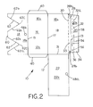
- FIG. 2 is a bottom plan view of the unassembled book insert CD carrier device of FIG. 1 shown with the printable side (i.e., the glossy side) exposed;
- FIG. 3 is a top plan view similar to FIG. 1 but showing preferred dimensions for the unassembled book insert CD carrier device constructed in accordance with the teachings of a first preferred embodiment of the present invention and again showing the un-printed side (i.e., the non-glossy side) exposed;
- FIG. 4 is a perspective view an assembled book insert CD carrier device attached to the interior rear cover of a book
- FIG. 5 is a perspective view of the book insert CD carrier device of FIG. 4 shown with the tear away strip removed to permit opening of the device in book form;
- FIG. 6 is an enlarged cross-sectional view taken along line 6 — 6 of FIG. 5;
- FIG. 7 is a plan view of the book insert CD carrier device in a partially folded position
- FIG. 8 is a plan view similar to FIG. 7 but showing the carrier device in another partially folded position
- FIG. 9 is a plan view similar to FIGS. 6 and 7 but showing the carrier device in a fully folded position.
- FIG. 10 is a plan view of the carrier device similar of FIG. 9 after rotating the carrier device about a vertical axis and showing the carrier device as it would appear upon when secured to the back cover of a book.
- the CD carrier device 10 includes a single paper board sheet 12 having two opposing surfaces, one of which is non-glossy surface 12 a (see FIG. 1) and the other which is a glossy surface 12 b (see FIG. 2 ).
- the sheet 12 which is preferably a stock of 12 point sheet board stock (12 pt SBS) is partitioned into a plurality of panels that are divided from one another by a plurality of hinge lines as will be described in greater detail below.
- the various panels are foldable about the appropriate hinge lines and secured as necessary to form the carrier device 10 .
- the carrier device 10 may be subsequently attached to a receiving area 11 inside a book 13 .
- the receiving area 11 is defined by a portion of a rear cover 13 a of the book 13 .
- the carrier device 10 may also be attached to a front cover 13 b of the book 13 .
- the carrier device 10 may be attached to either an interior surface or and exterior surface of the rear cover 13 a or the front cover 13 b of the book 13 .
- the carrier device 10 includes five panels 14 , 16 , 18 , 20 and 22 .
- a first hinge line 15 separates the panels 14 and 16
- a second hinge line 17 separates the panels 16 and 18
- a third hinge line 19 separates the panels 18 and 20
- a fourth hinge line 21 separates the panels 18 and 22 .
- the shape of the paperboard sheet 12 may be formed using conventional techniques, and the hinge lines 15 , 17 , 19 and 21 may be formed using conventional techniques.
- each of the panels 14 , 16 , 18 , 20 and 22 includes a non-glossy surface 14 a , 16 a , 18 a , 20 a , and 22 a , respectively.
- each of the panels 14 , 16 , 18 , 20 and 22 includes a glossy surface 14 b , 16 b , 18 b , 20 b , and 22 b , respectively.
- at least the glossy surfaces 14 b and 22 b may include graphics 14 c , 22 c , respectively.
- Other of the glossy surfaces 16 b , 18 b and 22 b may include graphics (not shown) as desired.
- the pockets 24 are sized to receive a CD 26 .
- the pockets 24 are side loading (i.e., the pockets 24 load sideways in a direction generally perpendicular to a spine 13 c of the book 13 rather than up or down in a direction generally parallel to the spine 13 c ).
- Other loading configurations, including up, down, or along a diagonal are possible.
- the CD or CD's 26 may include printed graphics 26 a.
- a tear away strip 28 is provided, with the tear away strip being bounded by a frangible connection 30 on the third panel 18 and by a frangible connection 32 on the fourth panel 20 .
- both the frangible connections 30 and 32 are formed by lines of perforations.
- the frangible connection 32 may be formed of a line of elongated slit perforations 32 a .
- Other forms of frangible connections may be employed.
- the tear away strip 28 may be of the type commonly employed in shipping envelopes and the like.
- the third panel 18 includes a removable portion 33 .
- the removable portion 33 is bounded by the frangible connection 30 on the third panel 18 and by the third hinge line 19 .
- the fourth panel 20 includes a fixable portion 34 and a removable portion 36 .
- the removable portion 36 of the fourth panel 20 is bounded by the hinge line 19 and the frangible connection 32 .
- the third hinge line 19 is not frangible, and thus upon removal of the tear away strip 28 , the frangible connections 30 and 32 are separated from their adjacent panels 18 , 20 , respectively. Accordingly, the removable portion 36 of the panel 20 and the removable portion 33 of the panel 18 are removed.
- the fixable portion 34 cooperates with a portion of the second panel to form a binding face 38 (viewable in FIG. 6 ).
- the binding face 38 may be positioned to be secured to the receiving area 11 of the book 13 as shown in FIG. 6 .
- the fixable portion 34 of the panel 20 (along with the balance of the carrier device 10 ) remain secured to the book 13 .
- the second panel 16 preferably includes a pair of side tabs 40 , with each of the side tabs having an adhesive strip 42 (preferably a peel and seal adhesive strip of the type commonly employed in the printing and binding arts).
- Another adhesive strip 44 may also be provided, with the adhesive strip 44 extending across a width of the second panel 16 to form a divider 46 between the pockets 24 .
- two portions 48 a and 48 b of a hook and loop closure may be provided to secure the device 10 closed upon removal of the tear away strip 28 (FIG. 5 ).
- the portion 48 a is disposed on the panel 22 (on the glossy surface 22 b ), while the portion 48 b is disposed on the panel 14 (on the glossy surface 14 a ).
- the fifth panel 22 may also include one or more adhesive strips 50 (again, preferably peel and seal adhesive strips) in order to secure the fifth panel 22 to the third panel 18 upon folding of the fifth panel 22 along the fourth hinge line 21 .
- the binding face 38 may be secured to the inside surface of the rear cover 12 a of the book 13 .
- the fixable portion 34 of the fourth panel 20 does not need to be secured to the second panel 16 .
- that portion of the non-glossy surface 20 a disposed on the fixable panel 34 does not need to be glued or secured to the glossy surface 16 b of the panel 16 after folding the carrier device 10 to the position of FIG. 9 .
- Both the fixable portion 34 and the panel 16 (together forming the binding face 38 , which is shown in cross-hatching in FIG. 9) are secured to the receiving area 11 of the book 13 using an adhesive 52 (FIG. 6) applied in a final assembly step.
- a portion 54 of the panel 20 overlaps an adjacent portion of the panel 16 , with the portion 54 being bounded by the points indicated by lines 56 and 58 . It will be noted that according to the preferred embodiment of the invention, the portion 54 has a width that extends across the adjacent panel 16 a distance of at least twenty-five percent of the width of the panel 16 .
- the panel 14 includes an edge 60 having one or more cutouts 62 .
- Each cutout 62 includes a pair of edges 62 a , 62 b , which converge at a vertex 62 c .
- the edges 62 a , 62 b and the vertex 62 c are sized and located such that the cutouts 62 reveal a generally pie-shaped portion 64 of the CD 26 inserted in one or more of the pockets 24 .
- the cutouts 62 will extend to include an aperture 27 on each of the CDs 26 .
- the vertex 62 of each cutout 62 may be located so as to reveal the central aperture on the CD or CDs 26 .
- the graphics 14 c on the surface 14 b of the panel 14 may complement the graphics 26 a printed on a face of the CD or CDs 26 .
- Other forms of cutouts, pockets, receiving slots, etc. sufficient to hold the CDs in place may be used.
- the carrier device 10 may initially be disposed on the position of FIG. 1 .
- the panels 22 and 14 are folded along their respective hinge lines 21 and 15 to the position of FIG. 7 .
- the side tabs 40 are folded inwardly from the position of FIG. 1 to the position of FIG. 7 in which the side tabs 40 overlap and engage the panel 14 .
- the panel 22 is secured in place by the adhesive strips 50 , while the panel 14 is secured in pace by the adhesive strips 42 on the side tabs 40 , and by the adhesive strip 44 in the central portion of the panel 16 .
- the adhesive strips 50 may be disposed on the panel 18 , while the adhesive strip 44 may be disposed in the panel 14 .
- the side tabs 40 may be formed on the panel 14 .
- the side tabs 40 may have the adhesive strips 42 on the opposite face from that shown such that the side tabs 40 would be disposed under the panel 14 when the panel 14 is positioned as shown in FIG. 7 .
- the carrier device 10 is disposed in the position of FIG. 7, it will be noted that the pockets 24 are formed, with the pockets 24 being separated by the divider 46 .
- a CD 26 may be loaded into one or both of the pockets 24 at this juncture.
- the panels 14 , 16 are then folded as a unit along the hinge line 17 , such that the panels 14 , 16 are brought into confronting relationship with the panels 18 and 22 (e.g., the glossy surface of the panel 14 faces the glossy surface of the panel 22 ).
- the carrier device 10 is now disposed as shown in FIG. 8 .
- FIG. 9 illustrates the binding face 38 in cross-hatching. Note that the portion of the glossy surface 20 b disposed on the removable portion 36 of the panel 20 does require adhesive and thus is not included in the binding face 38 .
- the next step in the outlined method of assembly is to fold the panel 20 along the hinge line 19 . This brings the device into the configuration shown in FIG. 9 .
- the frangible connection 32 extends past the tear away strip 28 and the frangible connection 30 .
- the carrier device 10 When it is desired to secure the carrier device 10 in a book 13 , the carrier device 10 is oriented as necessary to bring the binding face 38 into contact with the receiving area 11 of the book 13 . When viewing FIGS. 9 and 10, this is accomplished by rotating the carrier device 10 about a vertical axis from the position of FIG. 9 (with the binding face 38 facing up from the plane of the Fig.) to the position of FIG. 10 (with the binding face 38 facing into the plane of the Fig.). The adhesive 52 may be applied, and the carrier device 10 may be secured to the book 13 using conventional assembly techniques.
- FIGS. 5 and 6 when a user (not shown) wishes to gain access to the CD or CDs 26 disposed in the pocket or pockets 24 , the user may first position the book 13 as shown in FIG. 6 .
- the tear away strip 28 is still intact.
- the user grasps a pull tab 28 a or 28 b at either end of the tear away strip 28 , and pulls on the tear away strip 28 .
- This action severs the frangible connections 30 and 32 .
- the removable portion 33 of the panel 18 and the removable portion 36 of the panel 20 are removed in this process.
- the fixable portion 34 (which forms a portion of the binding face 38 ) remains secured to the receiving area 11 of the book 13 .
- the carrier device 10 may again be closed by pivoting the attached panels 18 and 22 in conjunction about the hinge line 17 in the opposite direction, thus bringing the panels 18 and 22 into confronting relationship with the panels 14 and 16 (e.g., the glossy surface 22 b faces the glossy surface 14 b ).
- the carrier device 10 may be secured on the closed position using the cooperating portions 48 a and 48 b of the hook and loop closure.
- hinge lines described herein may include any type of hinge line, including, for example, scored hinge lines or slitted hinge lines that lend flexibility to the hinge and thereby facilitate folding about the hinge line. Other suitable hinge lines may be used as well.
- the carrier device 10 may instead be configured and sized to hold fewer or more CDs and thus may include additional or fewer pockets.
- the carrier device 10 may instead be attached to the exterior cover of the book 13 , which may be hard cover or soft cover, or any other desired, similarly sized media.
- the glossy surface 12 b is generally exposed.
- a glossy surface is generally more suitable for receiving printed graphics in the form of text, pictures, graphics, symbols, or any other desired artistic representations.
- the majority of the exposed surface of the carrier device 10 may include such printed graphics.
- the graphics 14 c and 22 c on the panels 14 and 22 , respectively are visible to the user.
- the bulk of the non-glossy surface 12 a is not exposed as it may form the interior surface of the carrier device 10 , or it may form an insignificant portion of the exposed surface.
- the user may be presented with an array of printed graphics, as the glossy surface 22 b of the panel 22 and the glossy surface 14 b of the panel 14 are both exposed. Further, when the device is positioned as shown in FIG. 10, the user may be presented with graphics 18 c printed on the glossy surface 18 b of the panel 18 .
- a carrier device which may be used as a book insert has been provided.
- a book vendor may be provided with a carrier device for packaging a book in conjunction with one or more CDs as a single unit, thereby facilitating the unitary sale of two different information presentation formats in a single product.
- a CD carrier device provides a carrier device that is suitable for carrying CDs or similarly shaped objects and which may be readily attached to the front or rear covers of a book or any other suitable structure.
- the present carrier device 10 when fully assembled, presents a tamper evident structure. That is, the CD or CDs cannot be removed or tampered with without first removing the tear away strip 28 as detailed above. Thus, a vendor, a purchaser, or a user can be immediately whether the carrier device 10 has been tampered with simply by viewing the state of the tear away strip 28 .
Landscapes
- Business, Economics & Management (AREA)
- Engineering & Computer Science (AREA)
- Educational Administration (AREA)
- Educational Technology (AREA)
- Packaging For Recording Disks (AREA)
Abstract
Description
Claims (31)
Priority Applications (1)
| Application Number | Priority Date | Filing Date | Title |
|---|---|---|---|
| US09/965,612 US6648136B2 (en) | 2001-01-08 | 2001-09-27 | Book insert compact disc carrier device |
Applications Claiming Priority (2)
| Application Number | Priority Date | Filing Date | Title |
|---|---|---|---|
| US26057601P | 2001-01-08 | 2001-01-08 | |
| US09/965,612 US6648136B2 (en) | 2001-01-08 | 2001-09-27 | Book insert compact disc carrier device |
Publications (2)
| Publication Number | Publication Date |
|---|---|
| US20020089165A1 US20020089165A1 (en) | 2002-07-11 |
| US6648136B2 true US6648136B2 (en) | 2003-11-18 |
Family
ID=26948075
Family Applications (1)
| Application Number | Title | Priority Date | Filing Date |
|---|---|---|---|
| US09/965,612 Expired - Lifetime US6648136B2 (en) | 2001-01-08 | 2001-09-27 | Book insert compact disc carrier device |
Country Status (1)
| Country | Link |
|---|---|
| US (1) | US6648136B2 (en) |
Cited By (4)
| Publication number | Priority date | Publication date | Assignee | Title |
|---|---|---|---|---|
| US20070006713A1 (en) * | 2005-07-08 | 2007-01-11 | Dunlop Manufacturing, Inc. | Guitar pick package |
| US20090011163A1 (en) * | 2006-03-09 | 2009-01-08 | Manoj Ajbani | Compatibalized Blends of Polyphenylene Sulfide and Thermoplastic Vulcanizate |
| USD586209S1 (en) | 2007-12-14 | 2009-02-10 | Charles Cadmus | Blank for a CD periodical insert |
| US20140097108A1 (en) * | 2012-10-05 | 2014-04-10 | Jeffrey N. Olsen | Envelopes and folders with digital media storage |
Families Citing this family (1)
| Publication number | Priority date | Publication date | Assignee | Title |
|---|---|---|---|---|
| EP1492118A3 (en) * | 2003-06-24 | 2006-08-23 | Parichat Yavirat | Blank for CD envelope |
Citations (10)
| Publication number | Priority date | Publication date | Assignee | Title |
|---|---|---|---|---|
| US4620630A (en) * | 1985-10-18 | 1986-11-04 | Moss Ira L | Compact disc in convertible enclosure |
| US5333728A (en) * | 1993-08-30 | 1994-08-02 | Ivy Hill Corporation | Compact disc jacket and blank therefor |
| US5638953A (en) * | 1996-04-22 | 1997-06-17 | Jefferson Smurfit Corporation | Magazine insert holder for compact disk |
| US5697496A (en) * | 1995-10-20 | 1997-12-16 | Mcqueen, Inc. | Package for compact disks or computer diskettes |
| US5857565A (en) * | 1997-08-22 | 1999-01-12 | Arthur Meyer | Paperboard envelope for a computer disc or CD which is insertable in a bound publication |
| US6032795A (en) * | 1996-04-12 | 2000-03-07 | Activation Sweden Ab | Package assembly for keeping, storing, displaying and handling disc-shaped products |
| US6068117A (en) * | 1999-07-14 | 2000-05-30 | R. R. Donnelley & Sons | Book insert CD carrier device |
| US6092653A (en) * | 1999-05-10 | 2000-07-25 | Pozzoli S.P.A. | Method for manufacturing cases for compact discs and the like |
| US6126201A (en) * | 1996-11-07 | 2000-10-03 | Inserts Usa, Inc. | Folder for binding and mailing compact discs |
| US6296112B1 (en) * | 1996-11-21 | 2001-10-02 | White Thorn, L.L.C. | Compact disc folder booklet |
-
2001
- 2001-09-27 US US09/965,612 patent/US6648136B2/en not_active Expired - Lifetime
Patent Citations (10)
| Publication number | Priority date | Publication date | Assignee | Title |
|---|---|---|---|---|
| US4620630A (en) * | 1985-10-18 | 1986-11-04 | Moss Ira L | Compact disc in convertible enclosure |
| US5333728A (en) * | 1993-08-30 | 1994-08-02 | Ivy Hill Corporation | Compact disc jacket and blank therefor |
| US5697496A (en) * | 1995-10-20 | 1997-12-16 | Mcqueen, Inc. | Package for compact disks or computer diskettes |
| US6032795A (en) * | 1996-04-12 | 2000-03-07 | Activation Sweden Ab | Package assembly for keeping, storing, displaying and handling disc-shaped products |
| US5638953A (en) * | 1996-04-22 | 1997-06-17 | Jefferson Smurfit Corporation | Magazine insert holder for compact disk |
| US6126201A (en) * | 1996-11-07 | 2000-10-03 | Inserts Usa, Inc. | Folder for binding and mailing compact discs |
| US6296112B1 (en) * | 1996-11-21 | 2001-10-02 | White Thorn, L.L.C. | Compact disc folder booklet |
| US5857565A (en) * | 1997-08-22 | 1999-01-12 | Arthur Meyer | Paperboard envelope for a computer disc or CD which is insertable in a bound publication |
| US6092653A (en) * | 1999-05-10 | 2000-07-25 | Pozzoli S.P.A. | Method for manufacturing cases for compact discs and the like |
| US6068117A (en) * | 1999-07-14 | 2000-05-30 | R. R. Donnelley & Sons | Book insert CD carrier device |
Non-Patent Citations (2)
| Title |
|---|
| Fig. 1 illustrating prior art book insert device. |
| Figs. 2 and 3 illustrating prior art book insert device. |
Cited By (5)
| Publication number | Priority date | Publication date | Assignee | Title |
|---|---|---|---|---|
| US20070006713A1 (en) * | 2005-07-08 | 2007-01-11 | Dunlop Manufacturing, Inc. | Guitar pick package |
| US20090011163A1 (en) * | 2006-03-09 | 2009-01-08 | Manoj Ajbani | Compatibalized Blends of Polyphenylene Sulfide and Thermoplastic Vulcanizate |
| USD586209S1 (en) | 2007-12-14 | 2009-02-10 | Charles Cadmus | Blank for a CD periodical insert |
| US20140097108A1 (en) * | 2012-10-05 | 2014-04-10 | Jeffrey N. Olsen | Envelopes and folders with digital media storage |
| US8967454B2 (en) * | 2012-10-05 | 2015-03-03 | Jeffrey N Olsen | Envelopes and folders with digital media storage |
Also Published As
| Publication number | Publication date |
|---|---|
| US20020089165A1 (en) | 2002-07-11 |
Similar Documents
| Publication | Publication Date | Title |
|---|---|---|
| US6068117A (en) | Book insert CD carrier device | |
| EP1454320B9 (en) | Packaging for multiple media discs and methods for making same | |
| US4709812A (en) | Compact disc package and a method of making same | |
| US7032746B2 (en) | Compact disk package and method of assembling same | |
| US5772019A (en) | Packaging arrangement for storage discs and method for making the same | |
| US6360887B1 (en) | Compact disc folder booklet | |
| US5638953A (en) | Magazine insert holder for compact disk | |
| US5857565A (en) | Paperboard envelope for a computer disc or CD which is insertable in a bound publication | |
| CA2042413A1 (en) | Compact disc case and blank for forming same | |
| US6640473B1 (en) | Greeting card with DVD | |
| US6942092B1 (en) | Sleeve for digital media disk | |
| WO1994027892A1 (en) | Folding support for a compact disc | |
| US6260703B1 (en) | Folded greeting card holding an audio recording and displaying related text | |
| US6648136B2 (en) | Book insert compact disc carrier device | |
| US6938759B2 (en) | Package for storing discs | |
| EP1058665A1 (en) | A pouch for a data carrier and method for manufacturing same | |
| JP3434884B2 (en) | Cardboard storage | |
| CA2672288A1 (en) | Media packaging | |
| JP3493257B2 (en) | Recording medium holder | |
| JP3358473B2 (en) | Disc storage body and booklet binding it | |
| EP1610331A1 (en) | Packaging for multiple media discs | |
| JPH09216679A (en) | Recording medium holder | |
| HK1070459B (en) | Packaging for multiple media discs and methods for making same | |
| JPH11154384A (en) | Flat holder | |
| JPH0811972A (en) | Disk-shaped recording medium receiving case and manufacture thereof |
Legal Events
| Date | Code | Title | Description |
|---|---|---|---|
| AS | Assignment |
Owner name: R.R. DONNELLEY & SONS COMPANY, A DELAWARE CORPORAT Free format text: ASSIGNMENT OF ASSIGNORS INTEREST;ASSIGNOR:KOEHN, ANNALEE;REEL/FRAME:012723/0187 Effective date: 20010904 |
|
| STCF | Information on status: patent grant |
Free format text: PATENTED CASE |
|
| CC | Certificate of correction | ||
| FPAY | Fee payment |
Year of fee payment: 4 |
|
| FPAY | Fee payment |
Year of fee payment: 8 |
|
| FPAY | Fee payment |
Year of fee payment: 12 |
|
| AS | Assignment |
Owner name: LSC COMMUNICATIONS US, LLC, ILLINOIS Free format text: ASSIGNMENT OF ASSIGNORS INTEREST;ASSIGNOR:R. R. DONNELLEY & SONS COMPANY;REEL/FRAME:040172/0401 Effective date: 20160901 |
|
| AS | Assignment |
Owner name: BANK OF AMERICA, N.A., AS ADMINISTRATIVE AGENT, TE Free format text: SECURITY AGREEMENT;ASSIGNOR:LSC COMMUNICATIONS US, LLC;REEL/FRAME:040213/0633 Effective date: 20160930 Owner name: WELLS FARGO BANK, NATIONAL ASSOCIATION, AS COLLATE Free format text: SECURITY AGREEMENT;ASSIGNOR:LSC COMMUNICATIONS US, LLC;REEL/FRAME:040213/0791 Effective date: 20160930 |
|
| AS | Assignment |
Owner name: BANK OF AMERICA, N.A., AS ADMINISTRATIVE AGENT, ILLINOIS Free format text: PATENT SECURITY AGREEMENT;ASSIGNOR:LSC COMMUNICATIONS US, LLC;REEL/FRAME:052678/0364 Effective date: 20200514 |
|
| AS | Assignment |
Owner name: WILMINGTON TRUST, NATIONAL ASSOCIATION, AS SUCCESSOR TRUSTEE AND COLLATERAL AGENT, MINNESOTA Free format text: ASSIGNMENT OF PATENT SECURITY AGREEMENTS;ASSIGNOR:WELLS FARGO BANK, NATIONAL ASSOCIATION, AS RESIGNING TRUSTEE AND COLLATERAL AGENT;REEL/FRAME:053309/0787 Effective date: 20200619 |
|
| AS | Assignment |
Owner name: LSC COMMUNICATIONS US, LLC, ILLINOIS Free format text: TERMINATION AND RELEASE OF SECURITY INTEREST IN PATENTS;ASSIGNOR:BANK OF AMERICA, N.A., AS ADMINISTRATIVE AGENT;REEL/FRAME:054660/0875 Effective date: 20201204 |
|
| AS | Assignment |
Owner name: LSC COMMUNICATIONS US, LLC, ILLINOIS Free format text: TERMINATION AND RELEASE OF SECURITY INTEREST IN PATENTS;ASSIGNOR:BANK OF AMERICA, N.A., AS ADMINISTRATIVE AGENT;REEL/FRAME:054669/0393 Effective date: 20201204 |
|
| AS | Assignment |
Owner name: WELLS FARGO BANK, NATIONAL ASSOCIATION, AS ADMINISTRATIVE AGENT, NEW YORK Free format text: NOTICE OF SECURITY INTERESTS;ASSIGNORS:LSC COMMUNICATIONS LLC (FORMERLY ACR III LIBRA HOLDINGS LLC);TOPS PRODUCTS LLC;CONTINUUM MARKETING SERVICES LLC;AND OTHERS;REEL/FRAME:054792/0973 Effective date: 20201204 Owner name: LSC COMMUNICATIONS US, LLC, NEW YORK Free format text: RELEASE BY SECURED PARTY;ASSIGNOR:WILMINGTON TRUST, NATIONAL ASSOCIATION;REEL/FRAME:054875/0298 Effective date: 20201204 |
|
| AS | Assignment |
Owner name: LSC COMMUNICATIONS BOOK LLC, ILLINOIS Free format text: ASSIGNMENT OF ASSIGNORS INTEREST;ASSIGNOR:LSC COMMUNICATIONS US, LLC;REEL/FRAME:055146/0808 Effective date: 20201204 |