US6646820B1 - Method for recording magnetic recording medium - Google Patents
Method for recording magnetic recording medium Download PDFInfo
- Publication number
- US6646820B1 US6646820B1 US09/869,947 US86994701A US6646820B1 US 6646820 B1 US6646820 B1 US 6646820B1 US 86994701 A US86994701 A US 86994701A US 6646820 B1 US6646820 B1 US 6646820B1
- Authority
- US
- United States
- Prior art keywords
- magnetic
- recording medium
- gap
- core half
- recording
- Prior art date
- Legal status (The legal status is an assumption and is not a legal conclusion. Google has not performed a legal analysis and makes no representation as to the accuracy of the status listed.)
- Expired - Fee Related, expires
Links
Images


Classifications
-
- G—PHYSICS
- G11—INFORMATION STORAGE
- G11B—INFORMATION STORAGE BASED ON RELATIVE MOVEMENT BETWEEN RECORD CARRIER AND TRANSDUCER
- G11B5/00—Recording by magnetisation or demagnetisation of a record carrier; Reproducing by magnetic means; Record carriers therefor
- G11B5/86—Re-recording, i.e. transcribing information from one magnetisable record carrier on to one or more similar or dissimilar record carriers
- G11B5/865—Re-recording, i.e. transcribing information from one magnetisable record carrier on to one or more similar or dissimilar record carriers by contact "printing"
-
- G—PHYSICS
- G11—INFORMATION STORAGE
- G11B—INFORMATION STORAGE BASED ON RELATIVE MOVEMENT BETWEEN RECORD CARRIER AND TRANSDUCER
- G11B5/00—Recording by magnetisation or demagnetisation of a record carrier; Reproducing by magnetic means; Record carriers therefor
- G11B5/74—Record carriers characterised by the form, e.g. sheet shaped to wrap around a drum
- G11B5/82—Disk carriers
-
- G—PHYSICS
- G11—INFORMATION STORAGE
- G11B—INFORMATION STORAGE BASED ON RELATIVE MOVEMENT BETWEEN RECORD CARRIER AND TRANSDUCER
- G11B5/00—Recording by magnetisation or demagnetisation of a record carrier; Reproducing by magnetic means; Record carriers therefor
- G11B5/127—Structure or manufacture of heads, e.g. inductive
- G11B5/187—Structure or manufacture of the surface of the head in physical contact with, or immediately adjacent to the recording medium; Pole pieces; Gap features
- G11B5/23—Gap features
Definitions
- the present invention relates generally to a method of magnetically recording predetermined information signals on a magnetic recording medium used in a magnetic recording/reproducing device.
- a magnetic recording/reproducing device has been increasing in recording density in order to achieve a small size and large capacity.
- apparatuses with an areal recording density of more than ten gigabits per square inch (15.5 Mbits/mm 2 ) are already available on the market.
- Practical use of memories with an areal recording density of 20 gigabits per square inch (31.0 Mbits/mm 2 ) has been discussed.
- the technique in this field has been progressing rapidly.
- a technique of tracking servo of the head plays an important role.
- a hard disk drive to which such a tracking servo technique is applied has areas (hereafter referred to as “preformat”) where a tracking servo signal, an address data signal, and a reproduction clock signal are recorded at predetermined angles over the circumference of a disk, that is, over 360 degrees.
- preformat areas where a tracking servo signal, an address data signal, and a reproduction clock signal are recorded at predetermined angles over the circumference of a disk, that is, over 360 degrees.
- the magnetic head reproduces such signals every predetermined interval, so that the magnetic head can scan a track correctly while the head position is verified and corrected.
- a tracking servo signal, an address data signal, and a reproduction clock signal are to be reference signals for the magnetic head to scan a track correctly. Therefore, precise positioning accuracy is required in recording the signals.
- a disk is incorporated into the drive, and then using a special servo recording apparatus, preformat recording is carried out with a magnetic head whose position is controlled precisely.
- the recording using a magnetic head is basically linear recording utilizing the relative movement between the magnetic head and a magnetic recording medium, and therefore, in the above-mentioned method of recording using the special servo recording apparatus while the magnetic head position is controlled precisely, preformat recording takes a long time and the servo recording apparatus is quite expensive, thus increasing the cost.
- the head scans a track correctly with a high S/N ratio as in reproducing data signals recorded in an area between servo areas, but also that in a signal track formed by the preformat recording, the magnitude of reproduction amplitude is steeply changed when the magnetic head deviates from a track to be scanned, i.e. the off-track characteristic is steep.
- the above-mentioned problems go against these requirements and make it difficult to carry out the precise tracking servo technique in the submicron track recording expected in the future.
- JP 10-40544 A discloses the following method. That is, magnetic portions of a ferromagnetic material are formed on a substrate in a pattern corresponding to information signals, which then is used as a master information carrier. The surface of the master information carrier is brought into contact with a surface of a sheet-like or disc-shaped magnetic recording medium on which a ferromagnetic film or a ferromagnetic powder coating layer is formed, and a predetermined magnetic field is applied. Then, the magnetized pattern corresponding to the information signals formed in the master information carrier is recorded into a magnetic recording medium.
- JP 10-40544 A with a recording magnetic field generated from the ferromagnetic film on the surface of the master information carrier magnetized in one direction, a magnetized pattern corresponding to the ferromagnetic film pattern in the master information carrier is transfer-recorded into the magnetic recording medium.
- a ferromagnetic film pattern corresponding to a tracking servo signal, an address data signal, a reproduction clock signal, or the like is formed on the surface of the master information carrier by photolithography or the like, so that preformat corresponding to the pattern can be recorded on the magnetic recording medium.
- the conventional recording with a magnetic head is basically a dynamic track recording based on the relative movement between the head and a medium.
- the method described above is characterized by a static area recording without being accompanied by relative movement between the master information carrier and a medium.
- the technique disclosed in JP 10-40544 A can provide the following quite useful effects with respect to the aforementioned problems in a preformat recording.
- the areal recording is employed, a significantly shorter time is required for the preformat recording as compared to that in a conventional recording method using a magnetic head.
- the expensive servo recording apparatus for carrying out recording while the magnetic head position is controlled precisely is not required. Consequently, the productivity in the preformat recording can be increased considerably and the production cost can be reduced.
- the static recording is carried out without being accompanied by relative movement between the master information carrier and a medium, the surface of the master information carrier and the surface of a magnetic recording medium can be brought into close contact with each other, thus minimizing the spacing between the both in recording. Furthermore, since no diffusion of the recording magnetic field due to the shape of a pole provided in the magnetic head is caused, magnetization at the track edges of the recorded preformat signals has excellent steepness in transition compared to the case of recording with a conventional magnetic head, thus achieving more accurate tracking.
- the present invention is intended to record high density information signals uniformly and stably in a magnetic recording medium, particularly a disc-shaped magnetic recording medium such as a fixed hard disk medium, a removable hard disk medium, a large capacity flexible medium, or the like, with high productivity in a short time.
- a method of recording magnetically on a magnetic recording medium of the present invention is based on a method in which using a master information carrier with an arranged pattern formed of magnetic portions of a ferromagnetic film on a substrate in a shape corresponding to predetermined information signals, the master information carrier is superposed on a magnetic recording medium with the magnetic portions facing the magnetic recording medium and the magnetic portions of the master information carrier are magnetized with a magnetizing head, thus transfer-recording the arranged pattern formed in the master information carrier into the magnetic recording medium as a magnetized pattern.
- the magnetizing head includes an annular magnetic circuit with a gap, and a strength of a magnetic field applied to the master information carrier by magnetic flux leaking from portions other than the gap is set to be 20% or less of that of a magnetic field applied to the master information carrier by magnetic flux leaking from the gap.
- signal information in an arranged pattern provided in the master information carrier can be transfer-recorded throughout the magnetic recording medium as signal information in a magnetized pattern uniformly and stably without causing deterioration in signal quality.
- a magnetic field for direct current erasing is applied to the magnetic recording medium with a magnetizing head to magnetize the magnetic recording medium in one direction, then the master information carrier is superposed on the magnetic recording medium magnetized in the one direction, and a magnetic field in an opposite direction to that of the magnetic field for direct current erasing is applied to the magnetic portions of the master information carrier with the magnetizing head, thus transfer-recording the arranged pattern formed in the master information carrier into the magnetic recording medium as a magnetized pattern.
- the magnetizing head includes a first magnetic core half and a second magnetic core half, the first magnetic core half and the second magnetic core half oppose each other to form an annular magnetic circuit with a gap, and the magnetizing head is designed to have one of the following shapes so that a strength of a magnetic field applied to the master information carrier by magnetic flux leaking from portions other than the gap is suppressed to be 20% or less of that of a magnetic field applied to the master information carrier by magnetic flux leaking from the gap.
- an outer periphery in a cross-section parallel to an annular magnetic path of the magnetic circuit has a substantially polygonal shape in which at least vertexes adjacent to the gap have a curved shape with a curvature of a radius of at least 0.5 mm.
- an outer periphery in a cross-section parallel to an annular magnetic path of the magnetic circuit may have a substantially polygonal shape in which at least vertexes adjacent to the gap have an interior angle of at least 100 degrees.
- an outer periphery in a cross-section parallel to an annular magnetic path of the magnetic circuit may have a substantially polygonal shape with a supposed vertex positioned on a center line of the gap in the vicinity of the gap and the supposed vertex has an internal angle in a range between 100 and 170 degrees.
- the sides adjacent to the supposed vertex on the center line of the gap in the magnetizing head may have an outwardly curved shape.
- an outer periphery in a cross-section parallel to an annular magnetic path of the magnetic circuit may have a substantially elliptical shape with no vertex.
- a magnetic recording/reproducing device can be provided, which includes a magnetic recording medium that has been subjected to preformat recording using the method according to the above-mentioned configuration.
- a hard disk drive also can be provided, which includes a disc-shaped magnetic recording medium incorporated therein, in which a magnetized pattern of predetermined information signals has been transfer-recorded into a magnetic film using the method with the above-mentioned configuration.
- FIG. 1 is a schematic sectional view showing an example of a device used for implementing a method of recording magnetically on a magnetic recording medium according to a first embodiment of the present invention.
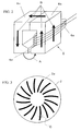
- FIG. 2 is a schematic perspective view of a magnetizing head.
- FIG. 3 is a plan view showing an example of a master information carrier used in the recording method of the present invention.
- FIG. 4 is a plan view used for explaining an example of an arranged pattern of information signals to be formed in the master information carrier shown in FIG. 3 .
- FIG. 5 is a sectional view showing an example of a master information carrier used in the recording method of the present invention.
- FIG. 6 is a perspective view showing a state where one-direction magnetic field is applied to a hard disk in the recording method of the present invention.
- FIG. 7 is a schematic perspective view showing a state of the hard disk magnetized in one direction in the process shown in FIG. 6 .
- FIG. 8 is a perspective view showing a state where information signals are transfer-recorded into the hard disk by the recording method of the present invention.
- FIG. 9 is a schematic perspective view showing a state of the hard disk in which the information signals are recorded in the process shown in FIG. 8 .
- FIG. 10 is a schematic sectional view used for explaining a state of a magnetized pattern when the information signals are transfer-recorded in the hard disk in the process shown in FIG. 8 .
- FIGS. 11A, 11 B, and 11 C show schematic views illustrating preferable recorded states in preformat recording by the recording method of the present invention.
- FIG. 12 is a diagram showing reproduced signals of information signals transfer-recorded by a conventional recording method.
- FIGS. 13A and 13B show schematic views illustrating a direct current erasing process according to the conventional recording method.
- FIGS. 14A and 14B show magnetization distributions in a magnetic recording medium after the direct current erasing and after the signal transfer-recording by the conventional recording method, respectively.
- FIG. 15 is a sectional view showing an example of a magnetizing head used in a second embodiment of the present invention.
- FIGS. 16A and 16B show schematic views illustrating a direct current erasing process when the magnetizing head shown in FIG. 15 is used.
- FIGS. 17A and 17B show magnetization distributions in a magnetic recording medium after the direct current erasing and after the signal transfer-recording using the magnetizing head shown in FIG. 15, respectively.
- FIG. 18 is a diagram showing reproduced signals of information signals transfer-recorded using the magnetizing head shown in FIG. 15 .
- FIG. 19 is a sectional view showing an example of a magnetizing head used in a third embodiment of the present invention.
- FIG. 20 is a sectional view showing an example of a magnetizing head used in a fourth embodiment of the present invention.
- FIG. 21 is a sectional view showing a modified example of the magnetizing head shown in FIG. 20 .
- FIG. 22 is a sectional view showing an example of a magnetizing head used in a fifth embodiment of the present invention.
- FIG. 23 is a sectional view showing an example of a magnetizing head used in a sixth embodiment of the present invention.
- FIG. 24 is a sectional view showing an example of a magnetizing head used in a seventh embodiment of the present invention.
- FIG. 1 shows a schematic view of a recording device used for implementing the recording method according to the present embodiment.
- numeral 1 denotes a disc-shaped hard disk as a disc-shaped magnetic recording medium.
- the hard disk 1 is produced by deposition of a ferromagnetic film made of Co or the like on a surface of a doughnut-disc-shaped aluminum substrate with a center hole 1 a by sputtering.
- Numeral 2 is a disc-shaped master information carrier that is positioned to be superposed on a surface of a magnetic film made of a ferromagnetic film or the like of the hard disk 1 so as to be in contact with the surface of the magnetic film.
- This master information carrier 2 has a larger diameter than that of the hard disk 1 and a signal area 2 a made of a ferromagnetic film on a surface in contact with the hard disk 1 .
- the ferromagnetic film of the signal area 2 a has a minute arranged pattern corresponding to information signals to be transferred magnetically into the hard disk 1 .
- Numeral 3 indicates a disk supporter for supporting the hard disk 1 .
- This disk supporter 3 is provided with a chucking portion 3 a for positioning and maintaining the hard disk 1 at its top.
- a suction hole 3 b communicating with the center hole 1 a of the hard disk 1 is provided, one end of which is connected to an exhaust duct 4 .
- an exhauster 5 is attached at an end of the exhaust duct 4 .
- the master information carrier 2 is attracted in the direction toward the hard disk 1 , and thus the hard disk 1 is superposed on the master information carrier 2 while being positioned with respect to the master information carrier 2 .
- a slight gap is present between the hard disk 1 and the master information carrier 2 and the air is drawn in from the outside through the gap as indicated by arrows shown in FIG. 1 .
- a magnetizing head 6 is used for transfer-recording signals from the master information carrier 2 into the hard disk 1 .
- the information signals are recorded into the hard disk 1 by a magnetic field generated by the magnetizing head 6 .
- the magnetizing head 6 includes opposed magnetic core halves 6 c and 6 b forming an annular magnetic circuit with a gap 6 d .
- the magnetic core halves 6 b and 6 c are made of a ferromagnetic material, and the magnetic core half 6 b is provided with a coil 6 a .
- leakage flux from the magnetic core half 6 c to the magnetic core half 6 b occurs in the vicinity of the gap 6 d as indicated by an arrow A.
- An arrow B indicates the direction of an internal magnetic flux occurring in the magnetic core halves 6 b and 6 c when the leakage flux in the direction shown in FIG. 2 occurs.
- the shape of the gap 6 d of the magnetizing head 6 is not shown in the figure, but the gap 6 d has the same circular-arc shape as that of a tracking scan orbit of a magnetic head for recording and reproduction when viewed from the master information carrier 2 side. Therefore, the direction of the magnetic field generated in the gap 6 d is always perpendicular to the tracking scan orbit. As a result, the ferromagnetic film of the master information carrier 2 is magnetized in the direction perpendicular to the direction of tracking scan by the magnetic head in every track. In other words, the ferromagnetic film is magnetized in the same direction as the direction corresponding to the gap length of the magnetic head.
- FIG. 3 shows a schematic plan view of an example of the master information carrier 2 .
- signal areas 2 a are formed in a substantially radial form.
- FIG. 4 shows an enlarged schematic view of the area C circled with an alternating long and short dash line in a signal area 2 a shown in FIG. 3 .
- a master information pattern formed of magnetic portions of a ferromagnetic film is formed at positions corresponding to digital information signals, for example, preformat records, to be recorded in a magnetic recording medium, in a pattern corresponding to the information signals.
- hatched portions are magnetic portions composed of the ferromagnetic film.
- the master information pattern shown in FIG. 4 includes areas of clock signals, tracking servo signals, address information signals, and the like, which are arranged sequentially in a disk circumferential direction, i.e. in a track length direction.
- the master information pattern shown in FIG. 4 merely is an example and its configuration, positions, and the like can be determined suitably according to digital information signals to be recorded in the magnetic recording medium.
- a hard disk drive when reference signals initially are recorded in a magnetic film of a hard disk and then preformat recording of tracking servo signals or the like is carried out based on the reference signals, only the reference signals to be used for the preformat recording are transfer-recorded into the magnetic film of the hard disk using the master information carrier. Then, the hard disk is inserted into a body of the drive, and the preformat recording of tracking servo signals or the like is carried out using a magnetic head of a hard disk drive. In this case, final preformat recording is carried out with a magnetic head mounted in the drive as in a conventional method.
- FIG. 5 shows a partial sectional view of the area C shown in FIGS. 3 and 4.
- the master information carrier 2 includes a disc-shaped substrate 10 made of a nonmagnetic material such as a Si substrate, a glass substrate, a plastic substrate, or the like.
- recessed portions 10 a are formed in a plurality of minute arranged pattern corresponding to information signals.
- a ferromagnetic film 11 forming magnetic portions is embedded.
- the surface 11 a of the ferromagnetic film 11 is as flat as possible and projects from the principal plane 10 b of the substrate 10 .
- the ferromagnetic film 11 many types of magnetic materials can be used irrespective of whether it is a hard-magnetic material, a semi-hard magnetic material, or a soft magnetic material. In short, any material can be used as long as it allows digital information signals to be transfer-recorded into a magnetic recording medium. For instance, Fe, Co, a Fe—Co alloy, or the like can be used. In order to generate a sufficient recording magnetic field irrespective of the type of the magnetic recording medium into which master information is recorded, it is preferable that the magnetic material has a higher saturation magnetic flux density.
- a magnetic disk with a high coercive force exceeding 2000 oersted (159 kA/m) or a flexible disk with a very thick magnetic layer proper recording may not be performed in some cases when the saturation magnetic flux density is 0.8 tesla or lower.
- magnetic materials with a saturation magnetic flux density of at least 0.8 tesla, preferably at least 1.0 tesla are used.
- the thickness of the ferromagnetic film 11 depends on a bit length, saturation magnetization in the magnetic recording medium, and thickness of the magnetic layer, but may be about 50 nm to 500 nm when, for example, the bit length is about 1 ⁇ m, the saturation magnetization and the thickness of a magnetic layer of the magnetic recording medium are about 500 emu/cc (500 kA/m) and about 20 nm, respectively.
- the arranged pattern of the ferromagnetic film 11 provided in the master information carrier is excited to be magnetized uniformly in preformat recording. Furthermore, it is desirable that prior to the signal recording using the master information carrier, the magnetic recording medium such as a hard disk is subjected to uniform direct current erasing.
- the following description is directed to a procedure for recording information signals, which correspond to a pattern formed in the master information carrier, into a hard disk as a disc-shaped magnetic recording medium.
- a magnetizing head 6 is rotated in parallel to the hard disk 1 about the center axis of the hard disk 1 as the rotation axis while being positioned close to the hard disk 1 .
- the hard disk 1 is pre-magnetized in one direction as indicated by arrows shown in FIG. 7 (initial magnetization).
- the exhauster 5 is started while the master information carrier 2 is positioned and superposed on the hard disk 1 .
- the master information carrier 2 is attracted through the center hole 1 a of the hard disk 1 , thus allowing a uniform contact between the hard disk 1 and the surface with the ferromagnetic film 11 of the master information carrier 2 .
- the magnetizing head 6 is set so that it generates a magnetic field in the opposite direction to that of the magnetic field generated by the initial magnetization.
- a dc excitation magnetic field is applied to the master information carrier 2 .
- the ferromagnetic film 11 of the master information carrier 2 is magnetized.
- information signals corresponding to the pattern of magnetic portions composed of the ferromagnetic film 11 are recorded in the predetermined area 1 b of the hard disk 1 on which the master information carrier 2 has been superposed, as shown in FIG. 9 .
- the arrows shown in FIG. 9 indicate the direction of magnetization remaining outside 1 b of the hard disk 1 after the information signals are recorded.
- FIG. 10 shows the state during the above-mentioned magnetization process.
- a magnetic field is applied to the master information carrier 2 from the outside to magnetize the ferromagnetic film 11 , thus recording information signals in the magnetic recording layer 1 c composed of the ferromagnetic film of the hard disk 1 .
- digital information signals can be magnetically transfer-recorded into the hard disk 1 of a magnetic recording medium.
- FIGS. 11A, 11 B, and 11 C show the procedure of the above-mentioned preformat recording by way of sectional views in a direction of the information signal track length.
- FIG. 11A shows a direct current erasing process with respect to the hard disk 1 of the magnetic recording medium.
- FIG. 11B shows a signal recording process using the master information carrier 2 .
- FIG. 11C shows a residual magnetization state of the hard disk 1 after the preformat recording.
- this magnetic recording medium is the hard disk 1
- the direction of the information signal track length coincides with the disk circumferential direction.
- the hard disk 1 of a magnetic recording medium is subjected to the uniform direct current erasing through the magnetization 13 in one direction by a magnetic field 12 for the direct current erasing prior to the transfer-recording of signals using the master information carrier.
- the surface of the master information carrier 2 in which the ferromagnetic film 11 is formed in an arranged pattern corresponding to information signals is brought into close contact with the surface of the hard disk 1 , and then the ferromagnetic film 11 is excited by a magnetic field 14 for direct current excitation.
- the magnetic field 14 has an opposite polarity to that of the magnetic field 12 .
- the magnetization 13 in the hard disk 1 is reversed by leakage flux 15 only in the portions between the respective portions of a ferromagnetic film 11 .
- a pattern of the magnetization 13 corresponding to the arranged pattern of the ferromagnetic film 11 formed in the master information carrier 2 can be recorded in the hard disk 1 .
- magnetic portions composed of a ferromagnetic film are preformed on the master information carrier in an arranged pattern corresponding to predetermined digital information signals to be recorded in the magnetic recording medium, the magnetic recording medium is brought into contact with the master information carrier, and the arranged pattern formed in the master information carrier is transfer-recorded into the magnetic recording medium as a magnetized pattern.
- FIG. 12 shows an example of the reproduced signals of preformat signals recorded in the hard disk as an example of the considerable deterioration in signal quality.
- FIG. 12 is an example of reproduced signals reproduced using a magnetoresistive head after periodic signals whose polarity is inverted at a predetermined interval are recorded for one revolution of a magnetic disk.
- the periodic signals were recorded with a uniform condition, the amplitude of the reproduced signals varies considerably depending on the positions in the disk circumferential direction.
- a magnetic recording/reproducing device cannot operate servo tracking using the preformat recording signals.
- leakage flux 16 leaking from an edge of a magnetic core of the magnetizing head 6 contributes to the magnetization process with respect to a magnetic recording medium.
- arrows inside the magnetizing head 6 indicate directions of internal flux.
- the leakage flux 16 leaking from the edge of the magnetic core has an opposite polarity to that of the leakage flux 15 from the gap primarily contributing to the direct current erasing. Therefore, the leakage flux 16 demagnetizes the portions that have been subjected to the direct current saturation erasing by the leakage flux 15 from the gap. Consequently, the magnetization 13 after the direct current erasing is in the state shown in FIG. 13 B.
- magnetization 18 in the magnetic recording medium after the direct current erasing is smaller than the residual magnetization M r in the magnetic recording medium by far, thus achieving no direct current saturation erasing.
- magnetization 18 in the magnetic recording medium is inverted to a residual magnetization ⁇ M r with a reversed polarity in the portions between the respective portions of a ferromagnetic film 17 a , as shown in FIG. 14B, by signal transfer-recording using a master information carrier, magnetization recorded in the magnetic recording medium is weak in the portions corresponding to the portions of the ferromagnetic film 17 , thus causing the reduction in the amplitude of reproduced signals as illustrated in FIG. 12 .
- the present invention is designed so that a magnetic field applied to an object to be magnetized by magnetic flux leaking from the portion other than the gap of the magnetizing head is suppressed to be 20% or less of a magnetic field applied to the object to be magnetized by the magnetic flux leaking from the gap of the magnetizing head.
- a magnetic field applied to an object to be magnetized by magnetic flux leaking from the portion other than the gap of the magnetizing head is suppressed to be 20% or less of a magnetic field applied to the object to be magnetized by the magnetic flux leaking from the gap of the magnetizing head.
- an influence of leakage flux with a reversed polarity that primarily does not contribute to the magnetic fields for the direct current erasing and the direct current excitation is suppressed to be within an acceptable range, thus preventing the deterioration in the signal quality.
- the “object to be magnetized” denotes a magnetic recording medium in the direct current erasing process and the ferromagnetic film in the master information carrier in the process of transfer-recording
- the magnetic field applied to the object to be magnetized by the magnetic flux leaking from the portion other than the gap of the magnetizing head is as close to zero as possible.
- the magnetic field applied to the object to be magnetized by the magnetic flux leaking from the portion other than the gap of the magnetizing head did not exceed 20%, a practically satisfactory result was obtained.
- it exceeded 20% as described with reference to FIG. 12, the variation in reproduced signal amplitude increased depending on the positions in the disk circumferential direction to cause the deterioration in quality of the reproduced signals, which made it difficult to carry out the servo tracking even when a correction was made using an electronic circuit.
- the magnetic field applied to the object to be magnetized by the magnetic flux leaking from the portion other than the gap of the magnetizing head is set to be 20% or less of the magnetic field applied to the object to be magnetized by the magnetic flux leaking from the gap.
- the present inventors found that the leakage flux with a reversed polarity that primarily did not contribute to the magnetic fields for the direct current erasing and the direct current excitation occurred due to the localized magnetic saturation in a magnetizing head caused by its shape.
- the use of a magnetizing head with a specific configuration and shape allows the magnetic field applied to the object to be magnetized by the magnetic flux leaking from the portion other than the gap of the magnetizing head to be suppressed to be 20% or less of the magnetic field applied to the object to be magnetized by the magnetic flux leaking from the gap.
- the following description is directed to configurations of magnetizing heads used in the recording method of the present invention, i.e. magnetizing heads that allow the magnetic field applied to the object to be magnetized by the magnetic flux leaking from the portion other than the gap of the magnetizing head to be suppressed to be 20% or less of the magnetic field applied to the object to be magnetized by the magnetic flux leaking from the gap.
- FIG. 15 shows a cross-section parallel to an annular magnetic path of a magnetic circuit of a magnetizing head, i.e. a cross-section in a track-length direction of information signals in a circumferential direction of, for example, a disc-shaped magnetic recording medium.
- This magnetizing head includes opposed first and second magnetic core halves 21 and 22 with yoke shapes forming an annular magnetic circuit with a gap 23 .
- outer periphery in the cross-section parallel to the annular magnetic path of the magnetic circuit is formed to have a substantially polygonal shape in which at least vertexes adjacent to the gap 23 have a curved shape.
- the outer periphery may have a shape in which at least vertexes adjacent to the gap 23 , i.e. vertexes 24 A, 24 B shown in the figure, are formed to have curved shapes with curvatures of radii r and r′ of at least 0.5 mm.
- the outer periphery has a substantially rectangular shape, but the shape is not limited to this.
- the outer periphery can have another polygonal shape such as a pentagonal or hexagonal shape as required.
- vertexes adjacent to the gap in the outer peripheral shape of a cross-section parallel to the annular magnetic path of the magnetic circuit reach magnetic saturation locally, resulting in the deterioration in signal quality due to the influence of the leakage flux leaking from the vertexes.
- the vertexes 24 A and 24 B adjacent to the gap are processed to have a curved shape with a curvature of a radius of at least 0.5 mm to provide a shape effect, thus suppressing the magnetic saturation at the vertexes 24 A and 24 B. Consequently, it is possible to suppress the occurrence of leakage flux from the vertexes 24 A and 24 B.
- FIGS. 16A and 16B show a direct current erasing process when using the magnetizing head according to the present embodiment.
- a magnetizing head 25 shown in FIG. 16A has a configuration as described above according to the present embodiment.
- leakage flux other than leakage flux 26 leaking from the gap primarily contributing to the direct current erasing makes no contribution to a process of magnetization of a hard disk 1 as a magnetic recording medium.
- magnetization 27 is formed as shown in FIG. 16 B.
- magnetization 29 in the magnetic recording medium after the direct current erasing reaches residual magnetization M r uniformly irrespective of the positions, thus achieving direct current saturation erasing.
- the magnetization 29 in the magnetic recording medium shown in FIG. 17A is inverted to be residual magnetization ⁇ M r with a reversed polarity as shown in FIG. 17B, thus achieving the saturation recording of a magnetized pattern in the magnetic recording medium corresponding to a ferromagnetic film pattern formed in the master information carrier.
- FIG. 18 shows an example of reproduction signals obtained when using a magnetizing head with the configuration of the present embodiment, in which periodic signals whose polarity was inverted at a certain interval were transfer-recorded into a hard disk for one revolution and then were reproduced using a magnetoresistive head.
- the signals were different from the reproduced signals of the conventional example shown in FIG. 12 and high quality reproduced signals with a larger amplitude and a smaller variation in amplitude depending on the position were obtained stably.
- the radii r and r′ were illustrated to be the same, but it is not always necessary for the both to be the same.
- the magnetic saturation at the vertexes 24 A and 24 B cannot be suppressed sufficiently. Therefore, in the direct current erasing process and the signal transfer-recording process, it is difficult to suppress the magnetic field applied to the object to be magnetized by the magnetic flux leaking from the portion other than the gap to be 20% or less of the magnetic field applied to the object to be magnetized by the magnetic flux leaking from the gap. Consequently, such high quality reproduced signals as shown in FIG. 18 might not be obtained in some cases.
- the radii r and r′ when the radii r and r′ are too large, the cross-sectional areas of the magnetic path in the vicinities of the vertexes 24 A and 24 B become small locally, and as a result, conversely the magnetic saturation in those portions may be increased. Therefore, when the radii r and r′ are increased to be several millimeters or more, it is necessary to increase sufficiently the cross-sectional areas of the magnetic paths in the vertexes 24 A and 24 B of the first and second magnetic core halves 21 and 22 depending on the radii. In the present embodiment, the radii r and r′ were set to be 2 mm, so that an effect of the present invention was obtained sufficiently. As a result, high quality reproduced signals as shown in FIG. 18 were obtained stably.
- FIG. 15 shows an example in which the whole magnetic core is formed of a permanent magnet material.
- a first magnetic core half 21 and a second magnetic core half 22 are magnetized uniformly in a direction along an annular magnetic path of a magnetic circuit formed of the first and second magnetic core halves 21 and 22 .
- the first and second magnetic core halves 21 and 22 have a residual magnetic flux density of at least 1.0 tesla and a coercive force of at least 10000 oersted (796 kA/m).
- a permanent magnet having such characteristics a rare-earth magnet containing a material of Nd—Fe—B, Sm—Co, or the like as a main component can be used.
- the outer dimension of the magnetizing head can be varied according to the shape of a magnetic recording medium subjected to preformat recording.
- the core length (indicated as L in FIG. 15) and the gap length (indicated as G in FIG. 15) of the magnetizing head are set to be about 5 mm to 30 mm and about 0.5 mm to 3 mm, respectively.
- the direction of a core width (a width in a direction normal to the paper showing FIG. 15) in the magnetizing head coincides with a track width direction of information signals to be transfer-recorded. Therefore, the increase in the core width allows recording to be carried out for an increased number of tracks at a time.
- a signal recording area in the radial direction of the hard disk is positioned between the diameters of about 21 mm and 46 mm. Therefore, as an example, a core width in the magnetizing head is set to be about 25 mm to 30 mm so as to substantially cover the whole area.
- the magnetizing heads described later in the third to seventh embodiments may have the same outer dimension as in the above.
- FIG. 19 shows a cross-section parallel to an annular magnetic path of a magnetic circuit, i.e. a cross-section in a track-length direction of information signals, for example, in a circumferential direction of a disc-shaped magnetic recording medium.
- This magnetizing head includes opposed first and second magnetic core halves 31 and 32 with yoke shapes forming an annular magnetic circuit with a gap 33 . Its outer periphery in the cross-section parallel to the annular magnetic path of the magnetic circuit is formed to have a substantially polygonal shape in which at least vertexes adjacent to the gap 33 have an interior angle of at least 100 degrees.
- the outer periphery in the cross-section parallel to the annular magnetic path of the magnetic circuit is formed to have a substantially polygonal shape in which at least vertexes 34 A and 34 B adjacent to the gap 33 have interior angles ⁇ and ⁇ ′ of at least 100 degrees.
- the outer periphery has a substantially hexagonal shape, but the present embodiment is not limited to this.
- the outer periphery can have another polygonal shape as required.
- the vertex portions tend to reach magnetic saturation easily.
- the vertexes 34 A and 34 B adjacent to the gap 33 are processed to have interior angles ⁇ and ⁇ ′ of at least 100 degrees to provide a shape effect. Due to the shape effect, the magnetic saturation in the portions of the vertexes 34 A and 34 B is suppressed and thus the occurrence of the leakage flux from the portions can be suppressed.
- the portions of vertexes 34 C and 34 D adjacent to the vertexes 34 A and 34 B, respectively have smaller interior angles. Therefore, leakage flux due to the magnetic saturation might occur in the portions.
- the vertexes 34 C and 34 D are positioned not in the vicinity of and relatively away from the surfaces of objects to be magnetized in the direct current erasing and signal transfer-recording processes. Therefore, the magnetic flux leaking from the portions does not affect the processes for magnetizing the objects to be magnetized and does not contribute to the deterioration in the quality of reproduced signals as shown in FIG. 12 .
- the interior angles ⁇ and ⁇ ′ were illustrated to be the same, but it is not always necessary for the both to be the same.
- the magnetic saturation at the vertexes 34 A and 34 B cannot be suppressed sufficiently. That is to say, in the direct current erasing process and the signal transfer-recording process, it is difficult to suppress the magnetic field applied to the object to be magnetized by the magnetic flux leaking from the portions other than the gap to be 20% or less of the magnetic field applied to the object to be magnetized by the magnetic flux leaking from the gap. Consequently, such high quality reproduced signals as shown in FIG. 18 might not be obtained in some cases.
- the interior angles ⁇ and ⁇ ′ are set to be wider than about 150 degrees, it is necessary to set the distances between the vertexes 34 A and 34 C and between the vertexes 34 B and 34 D to be sufficiently long to prevent the vertexes 34 C and 34 D from being positioned close to the surface of the objects to be magnetized.
- the interior angles ⁇ and ⁇ ′ are set to be about 100 degrees to 120 degrees, and the distances between the vertexes 34 A and 34 C and between the vertexes 34 B and 34 D to be at least about 1 mm. According to this, the effect of the present invention can be obtained sufficiently and high quality reproduced signals as shown in FIG. 18 can be obtained stably.
- a magnetizing head shown in FIG. 19 also is an example in which the whole magnetic core is formed of a permanent magnet material as in the configuration shown in FIG. 15 .
- the first magnetic core half 31 and the second magnetic core half 32 are magnetized uniformly in a direction along the annular magnetic path of the magnetic circuit formed of the first and second magnetic core halves 31 and 32 .
- the permanent magnet material used for the first and second magnetic core halves 31 and 32 the same materials as those used in the configuration shown in FIG. 15 can be used.
- FIG. 20 shows a cross-section parallel to an annular magnetic path of a magnetic circuit, i.e. a cross-section in a track-length direction of information signals, for example, in a circumferential direction of a disc-shaped magnetic recording medium.
- This magnetizing head includes opposed first and second magnetic core halves 41 and 42 with yoke shapes forming an annular magnetic circuit with a gap 43 .
- Its outer periphery in the cross-section parallel to the annular magnetic path of the magnetic circuit is formed to have a substantially polygonal shape with a supposed vertex 45 C, on a center line 44 of the gap 43 in the vicinity of the gap 43 , whose interior angle ⁇ is in the range between 100 and 170 degrees.
- its outer periphery has a substantially pentagonal shape, but the present embodiment is not limited to this.
- the outer periphery can have another polygonal shape as required.
- the vertexes 45 A and 45 B adjacent to the gap 43 have small interior angles and may cause leakage flux due to the magnetic saturation.
- the vertexes 45 A and 45 B are positioned not in the vicinity of but at a sufficient distance from the surface of objects to be magnetized in the direct current erasing and signal transfer-recording processes.
- the magnetic flux leaking from the vertexes 45 A and 45 B tends not to affect the processes of magnetizing the objects to be magnetized and thus does not contribute to the deterioration in the quality of reproduced signals as shown in FIG. 12 .
- the interior angle ⁇ is set to be in the range between about 100 and 170 degrees and the distances between the vertexes 45 A and 45 C and between the vertexes 45 B and 45 C to be at least about several millimeters.
- a magnetizing head shown in FIG. 20 also is an example in which the whole magnetic core is formed of a permanent magnet material as in the configuration shown in FIG. 15 .
- the first magnetic core half 41 and the second magnetic core half 42 are magnetized uniformly in a direction along the annular magnetic path of the magnetic circuit formed of the first and second magnetic core halves 41 and 42 .
- the permanent magnet material used for the first and second magnetic core halves 41 and 42 the same materials as those used in the configuration shown in FIG. 15 can be used.
- FIG. 21 a configuration shown in FIG. 21 also may be employed. That is to say, in an example shown in FIG. 21, an annular magnetic circuit with a gap 43 is formed of opposed first and second magnetic core halves 41 and 42 , and the sides extending between the supposed vertex 45 C on the center line 44 of the gap 43 and the vertex 45 A and between the supposed vertex 45 C and the vertex 45 B have a curved shape. This allows the magnetic saturation in the vicinity of the gap edge on the outer peripheral side of the annular magnetic path to be suppressed even in the case where the interior angle ⁇ is a relatively small. Therefore, sufficient leakage flux to the outside of the annular magnetic path can be obtained, which contributes as magnetic fields for the direct current erasing and the direct current excitation.
- FIG. 22 shows a cross-section parallel to an annular magnetic path of a magnetic circuit, i.e. a cross-section in a track-length direction of information signals, for example, in a circumferential direction of a disc-shaped magnetic recording medium.
- This magnetizing head includes opposed first and second magnetic core halves 51 and 52 with yoke shapes forming an annular magnetic circuit with a gap 53 . Its outer periphery in the cross-section parallel to the annular magnetic path of the magnetic circuit is formed to have a substantially elliptical shape including no vertex.
- the vertex portions adjacent to the gap in the outer peripheral shape of a cross-section parallel to the annular magnetic path reach magnetic saturation locally, resulting in the deterioration in signal quality due to the influence of the leakage flux leaking from the portions.
- the outer peripheral shape of the cross-section parallel to the annular magnetic path has no vertex except for the gap edge portion. Therefore, this configuration can achieve the configuration of the present invention most reliably in which the magnetic field applied to the object to be magnetized by the magnetic flux leaking from the portion other than the gap 53 of the magnetizing head is suppressed to be 20% or less of the magnetic field applied to the object to be magnetized by the magnetic flux leaking from the gap 53 .
- the magnetizing head shown in FIG. 22 also is an example in which the whole magnetic core is formed of a permanent magnet material as in the configuration shown in FIG. 15 .
- the first magnetic core half 51 and the second magnetic core half 52 are magnetized uniformly in a direction along the annular magnetic path of the magnetic circuit formed of the first and second magnetic core halves 51 and 52 .
- the permanent magnet material used for the first and second magnetic core halves 51 and 52 the same materials as those used in the configuration shown in FIG. 1 can be used.
- FIG. 23 shows a cross-section parallel to an annular magnetic path of a magnetic circuit, i.e. a cross-section in a track-length direction of information signals, for example, in a circumferential direction of a disc-shaped magnetic recording medium.
- This magnetizing head includes opposed first and second magnetic core halves 61 and 62 with yoke shapes forming an annular magnetic circuit with a gap 63 . Its outer periphery in the cross-section parallel to the annular magnetic path is basically the same as that of the embodiment shown in FIG.
- the magnetizing head according to the present embodiment has a configuration in which the first and second magnetic core halves 61 and 62 are positioned opposing each other with a permanent magnet 65 being interposed therebetween.
- the material forming the first and second magnetic core halves 61 and 62 not only the permanent magnet material but also various kinds of ferromagnetic materials with soft magnetism or semi-hard magnetism can be used.
- the ferromagnetic material forming the first and second magnetic core halves 61 and 62 has a sufficiently high saturation magnetic flux density so as not to cause considerable magnetic saturation locally due to the magnetic flux applied from the permanent magnet 65 .
- Fe, a Fe—Co alloy, a Fe—Si based soft magnetism alloy, or the like can be used.
- the magnetizing head according to the present embodiment can be manufactured more easily at a lower cost as compared to the aforementioned magnetizing heads.
- the permanent magnet 65 preferably, one with a residual magnetic flux density of at least 1.0 tesla and a coercive force of at least 10000 oersted (796 kA/m) is used as in the case of the magnetic cores in the above-mentioned configuration.
- a rare-earth magnet containing a material of Nd—Fe—B, Sm—Co, or the like as a main component can be used.
- the outer peripheral shape in the cross-section parallel to the annual magnetic path of the magnetizing head is the same as that of the example shown in FIG. 15 .
- the configuration according to the present embodiment also can be applied to the outer peripheral shapes corresponding to the embodiments shown in FIGS. 19 to 22 .
- FIG. 24 shows a cross-section parallel to an annular magnetic path of a magnetic circuit, i.e. a cross-section in a track-length direction of information signals, for example, in a circumferential direction of a disc-shaped magnetic recording medium.
- This magnetizing head includes opposed first and second magnetic core halves 71 and 72 with yoke shapes forming an annular magnetic circuit with a gap 73 . Its outer periphery in the cross-section parallel to the annular magnetic path has basically the same shape as that of the embodiment shown in FIG.
- the magnetizing head according to the present embodiment has a configuration in which a coil 75 is provided around at least one of the first and second magnetic core halves 71 and 72 for exciting them with a direct current. In the example shown in FIG. 24, the coil 75 is provided around the second magnetic core half 72 .
- the first and second magnetic core halves with yoke shapes are required to be magnetized uniformly in the direction along the annular magnetic path of the magnetic circuit formed of the magnetic core halves, but it may be difficult depending on the core shapes in some cases.
- the configuration according to the present embodiment since the core is excited with a current flowing in the coil 75 , it is not necessary to provide a permanent magnet as an element of the magnetic core, thus solving the troublesomeness of the magnetization in a proper direction.
- the material forming the first and second magnetic core halves 71 and 72 may not be a permanent magnetic material, and therefore, various kinds of ferromagnetic materials with soft magnetism or semi-hard magnetism can be used.
- the ferromagnetic material forming the first and second magnetic core halves 71 and 72 has a sufficiently high saturation magnetic flux density so as to apply sufficient magnetic fields for the direct current erasing and the direct current excitation by the leakage flux from the gap 73 .
- Fe for example, Fe, a Fe—Co alloy, a Fe—Si based soft magnetism alloy, or the like can be used as the ferromagnetic material.
- the outer peripheral shape in the cross-section parallel to the annual magnetic path is the same as that in the configuration shown in FIG. 15 .
- the configuration according to the present embodiment also can be applied to the outer peripheral shapes corresponding to the embodiments shown in FIGS. 19 to 22 .
- the magnetizing head used in the recording method of the present invention may have various forms.
- the spacing between such a magnetizing head and a magnetic recording medium is set to be within a proper range, the configuration of the present invention can be achieved reliably, in which the magnetic field applied to the object to be magnetized by the magnetic flux leaking from the portion other than the gap is suppressed to be 20% or less of the magnetic field applied to the object to be magnetized by the magnetic flux leaking from the gap.
- a sufficiently great tolerance of the spacing between the magnetizing head and the magnetic recording medium can be obtained.
- the present invention is not limited thereto.
- the present invention also can be applied to a magnetic recording medium such as a flexible magnetic disk, a magnetic card, a magnetic tape, and the like, and thereby the same effects as in the above can be obtained.
- the information signals to be recorded in a magnetic recording medium main consideration was given to the preformat signals such as tracking servo signals, address information signals, reproduction clock signals, or the like, but the information signals with respect to which the configuration of the present invention can be applied also are not limited thereto.
- the configuration of the present invention it also is possible on the principle to record various data signals and audio and video signals.
- the master information carrier of the present invention and the recording technique with respect to a magnetic recording medium using the same enables mass copy production of soft disk media to be carried out.
- high density information signals can be recorded uniformly and stably with high productivity in a short time on a magnetic recording medium, particularly a disc-shaped magnetic recording medium such as a fixed hard disk medium, a removable hard disk medium, a large capacity flexible medium, or the like.
- a magnetic recording medium particularly a disc-shaped magnetic recording medium such as a fixed hard disk medium, a removable hard disk medium, a large capacity flexible medium, or the like.
- the quality of the transfer-recorded signals does not deteriorate, thus providing recording technique in which excellent signal quality can be obtained in view of the assurance of product quality in mass production and the improvement in production yield.
Landscapes
- Recording Or Reproducing By Magnetic Means (AREA)
- Magnetic Record Carriers (AREA)
- Adjustment Of The Magnetic Head Position Track Following On Tapes (AREA)
Abstract
Description
Claims (23)
Applications Claiming Priority (5)
| Application Number | Priority Date | Filing Date | Title |
|---|---|---|---|
| JP11-324598 | 1999-11-15 | ||
| JP32459899 | 1999-11-15 | ||
| JP2000-334447 | 2000-11-01 | ||
| JP2000334447A JP3330927B2 (en) | 1999-11-15 | 2000-11-01 | Recording method on magnetic recording medium |
| PCT/JP2000/008006 WO2001037268A1 (en) | 1999-11-15 | 2000-11-13 | Method for recording magnetic recording medium |
Publications (1)
| Publication Number | Publication Date |
|---|---|
| US6646820B1 true US6646820B1 (en) | 2003-11-11 |
Family
ID=26571539
Family Applications (1)
| Application Number | Title | Priority Date | Filing Date |
|---|---|---|---|
| US09/869,947 Expired - Fee Related US6646820B1 (en) | 1999-11-15 | 2000-11-13 | Method for recording magnetic recording medium |
Country Status (5)
| Country | Link |
|---|---|
| US (1) | US6646820B1 (en) |
| JP (1) | JP3330927B2 (en) |
| CN (1) | CN1206629C (en) |
| MY (1) | MY123711A (en) |
| WO (1) | WO2001037268A1 (en) |
Cited By (4)
| Publication number | Priority date | Publication date | Assignee | Title |
|---|---|---|---|---|
| US20030117736A1 (en) * | 2001-12-20 | 2003-06-26 | Fuji Photo Film Co., Ltd. | Master information carrier for magnetic transfer |
| US20060132971A1 (en) * | 2003-12-15 | 2006-06-22 | Seagate Technology Llc | Magnetic recording head with compact yoke |
| US8208211B2 (en) * | 2009-07-15 | 2012-06-26 | Fuji Electric Co., Ltd. | Magnetic transfer device and magnetic transfer method |
| US10669424B2 (en) | 2013-09-30 | 2020-06-02 | Basf Se | Lignocellulosic composite articles |
Families Citing this family (4)
| Publication number | Priority date | Publication date | Assignee | Title |
|---|---|---|---|---|
| JP2002367165A (en) | 2001-06-08 | 2002-12-20 | Fuji Photo Film Co Ltd | Magnetic transfer method for high-density magnetic recording medium |
| JP3441444B2 (en) | 2001-08-30 | 2003-09-02 | 松下電器産業株式会社 | Head for magnetization |
| KR100460131B1 (en) * | 2002-05-08 | 2004-12-03 | 한국과학기술연구원 | Design optimization of plannar type write heads for ultra high density magnetic recording |
| CN100437817C (en) * | 2005-12-31 | 2008-11-26 | 中国科学院物理研究所 | Magnetic random access memory based on annular magnetic multilayer film and its control method |
Citations (10)
| Publication number | Priority date | Publication date | Assignee | Title |
|---|---|---|---|---|
| JPH0283285A (en) | 1988-09-21 | 1990-03-23 | Hitachi Ltd | Stabilization method for aluminum nitride |
| JPH02297081A (en) | 1989-05-12 | 1990-12-07 | Mineruba:Kk | Magnetic head |
| JPH0498605A (en) | 1990-08-17 | 1992-03-31 | Sony Corp | Thin-film magnetic head |
| JPH07220278A (en) | 1994-02-03 | 1995-08-18 | Otari Kk | Magnetic tape copying device |
| JPH0830915A (en) | 1994-07-12 | 1996-02-02 | Hitachi Ltd | Magnetic head |
| JPH1040544A (en) | 1996-07-22 | 1998-02-13 | Matsushita Electric Ind Co Ltd | Method for recording master information carrier and master information signal on magnetic recording medium |
| JPH10233006A (en) | 1996-12-17 | 1998-09-02 | Sony Corp | Magnetic head |
| EP0915456A1 (en) | 1996-07-22 | 1999-05-12 | Matsushita Electric Industrial Co., Ltd | Master information carrier, process for producing the carrier, and method and apparatus for recording master information signal on magnetic recording medium by using the carrier |
| US5923484A (en) * | 1995-08-31 | 1999-07-13 | Future Productions, Inc. | Method of changing a thermomagnetic tape duplicator to an anhysteretic type of tape duplicator |
| US6469848B1 (en) * | 1999-04-27 | 2002-10-22 | Matsushita Electric Industrial Co., Ltd. | Method and apparatus for manufacturing a magnetic recording medium with pre-format recording signals transferred and recorded by using a master information carrier |
-
2000
- 2000-11-01 JP JP2000334447A patent/JP3330927B2/en not_active Expired - Fee Related
- 2000-11-13 US US09/869,947 patent/US6646820B1/en not_active Expired - Fee Related
- 2000-11-13 CN CNB00802586XA patent/CN1206629C/en not_active Expired - Fee Related
- 2000-11-13 WO PCT/JP2000/008006 patent/WO2001037268A1/en not_active Ceased
- 2000-11-15 MY MYPI20005350A patent/MY123711A/en unknown
Patent Citations (10)
| Publication number | Priority date | Publication date | Assignee | Title |
|---|---|---|---|---|
| JPH0283285A (en) | 1988-09-21 | 1990-03-23 | Hitachi Ltd | Stabilization method for aluminum nitride |
| JPH02297081A (en) | 1989-05-12 | 1990-12-07 | Mineruba:Kk | Magnetic head |
| JPH0498605A (en) | 1990-08-17 | 1992-03-31 | Sony Corp | Thin-film magnetic head |
| JPH07220278A (en) | 1994-02-03 | 1995-08-18 | Otari Kk | Magnetic tape copying device |
| JPH0830915A (en) | 1994-07-12 | 1996-02-02 | Hitachi Ltd | Magnetic head |
| US5923484A (en) * | 1995-08-31 | 1999-07-13 | Future Productions, Inc. | Method of changing a thermomagnetic tape duplicator to an anhysteretic type of tape duplicator |
| JPH1040544A (en) | 1996-07-22 | 1998-02-13 | Matsushita Electric Ind Co Ltd | Method for recording master information carrier and master information signal on magnetic recording medium |
| EP0915456A1 (en) | 1996-07-22 | 1999-05-12 | Matsushita Electric Industrial Co., Ltd | Master information carrier, process for producing the carrier, and method and apparatus for recording master information signal on magnetic recording medium by using the carrier |
| JPH10233006A (en) | 1996-12-17 | 1998-09-02 | Sony Corp | Magnetic head |
| US6469848B1 (en) * | 1999-04-27 | 2002-10-22 | Matsushita Electric Industrial Co., Ltd. | Method and apparatus for manufacturing a magnetic recording medium with pre-format recording signals transferred and recorded by using a master information carrier |
Cited By (6)
| Publication number | Priority date | Publication date | Assignee | Title |
|---|---|---|---|---|
| US20030117736A1 (en) * | 2001-12-20 | 2003-06-26 | Fuji Photo Film Co., Ltd. | Master information carrier for magnetic transfer |
| US6879452B2 (en) * | 2001-12-20 | 2005-04-12 | Fuji Photo Film Co., Ltd. | Master information carrier for magnetic transfer |
| US20060132971A1 (en) * | 2003-12-15 | 2006-06-22 | Seagate Technology Llc | Magnetic recording head with compact yoke |
| US8144425B2 (en) * | 2003-12-15 | 2012-03-27 | Seagate Technology Llc | Magnetic recording head with compact yoke |
| US8208211B2 (en) * | 2009-07-15 | 2012-06-26 | Fuji Electric Co., Ltd. | Magnetic transfer device and magnetic transfer method |
| US10669424B2 (en) | 2013-09-30 | 2020-06-02 | Basf Se | Lignocellulosic composite articles |
Also Published As
| Publication number | Publication date |
|---|---|
| CN1335981A (en) | 2002-02-13 |
| MY123711A (en) | 2006-05-31 |
| JP2001209935A (en) | 2001-08-03 |
| WO2001037268A1 (en) | 2001-05-25 |
| CN1206629C (en) | 2005-06-15 |
| JP3330927B2 (en) | 2002-10-07 |
Similar Documents
| Publication | Publication Date | Title |
|---|---|---|
| JP3323743B2 (en) | Method for manufacturing master information carrier and magnetic recording medium | |
| US7149042B2 (en) | Master carrier for magnetic transfer | |
| JP4161540B2 (en) | Magnetic transfer method for perpendicular magnetic recording medium | |
| US6490129B1 (en) | Magnetic head including an inductive magnetic head having a lower magnetic core of a magnetic film/non-magnetic film/magnetic film multilayer structure | |
| US6611388B1 (en) | Master information magnetic recorder | |
| US7057834B2 (en) | Master information carrier and method for manufacturing magnetic disc using the same | |
| JP2005166230A (en) | Magnetic recording medium recording method, magnetic recording medium recording apparatus, and magnetic recording medium | |
| US6646820B1 (en) | Method for recording magnetic recording medium | |
| US6906876B2 (en) | Magnetic transfer method and apparatus | |
| JPH06180834A (en) | Perpendicular magnetic recording medium | |
| US7038868B2 (en) | Method of magnetic transfer and stopping slave medium rotation | |
| US7468852B2 (en) | Method of demagnetizing magnetic recording medium and apparatus for carrying out same | |
| JP4444797B2 (en) | Magnetic circuit for generating radial magnetic field used for film formation by sputtering process | |
| JP3424075B2 (en) | Method for manufacturing magnetic recording medium, magnetizing head for manufacturing magnetic recording medium, and magnetic transfer device | |
| JP3441444B2 (en) | Head for magnetization | |
| US7440207B2 (en) | Magnetic-transfer method, magnetic recording medium, and magnetic recording device | |
| JP4399023B2 (en) | Magnetic circuit for radial magnetic field generation used in heat treatment process | |
| JP2003296917A (en) | Magnetic recording medium | |
| JP3679765B2 (en) | Method for manufacturing magnetic recording medium | |
| KR20030065352A (en) | Magnetic recording media | |
| JP3424076B2 (en) | Method for manufacturing magnetic recording medium, magnetizing head for manufacturing magnetic recording medium, and magnetic transfer device | |
| JP3655212B2 (en) | Master information carrier and magnetic disk manufacturing method using the same | |
| JP2006244602A (en) | Magnetic recording / reproducing apparatus and manufacturing method thereof | |
| JP2006024255A (en) | Manufacturing method of magnetic disk, magnetic recording / reproducing apparatus, and manufacturing method of magnetic recording / reproducing apparatus |
Legal Events
| Date | Code | Title | Description |
|---|---|---|---|
| AS | Assignment |
Owner name: MATSUSHITA ELECTRIC INDUSTRIAL CO., LTD., JAPAN Free format text: ASSIGNMENT OF ASSIGNORS INTEREST;ASSIGNORS:ISHIDA, TATSUAKI;HAMADA, TAIZOU;HASHI, HIDEYUKI;AND OTHERS;REEL/FRAME:012125/0245 Effective date: 20010615 |
|
| FEPP | Fee payment procedure |
Free format text: PAYOR NUMBER ASSIGNED (ORIGINAL EVENT CODE: ASPN); ENTITY STATUS OF PATENT OWNER: LARGE ENTITY |
|
| FPAY | Fee payment |
Year of fee payment: 4 |
|
| FPAY | Fee payment |
Year of fee payment: 8 |
|
| AS | Assignment |
Owner name: PANASONIC CORPORATION, JAPAN Free format text: CHANGE OF NAME;ASSIGNOR:MATSUSHITA ELECTRIC INDUSTRIAL CO., LTD.;REEL/FRAME:033551/0062 Effective date: 20081001 |
|
| AS | Assignment |
Owner name: WESTERN DIGITAL TECHNOLOGIES, INC., CALIFORNIA Free format text: ASSIGNMENT OF ASSIGNORS INTEREST;ASSIGNOR:PANASONIC CORPORATION;REEL/FRAME:034650/0885 Effective date: 20141015 |
|
| REMI | Maintenance fee reminder mailed | ||
| LAPS | Lapse for failure to pay maintenance fees | ||
| STCH | Information on status: patent discontinuation |
Free format text: PATENT EXPIRED DUE TO NONPAYMENT OF MAINTENANCE FEES UNDER 37 CFR 1.362 |
|
| STCH | Information on status: patent discontinuation |
Free format text: PATENT EXPIRED DUE TO NONPAYMENT OF MAINTENANCE FEES UNDER 37 CFR 1.362 |
|
| FP | Lapsed due to failure to pay maintenance fee |
Effective date: 20151111 |