US6638693B2 - Process for making media for high quality ink jet printing - Google Patents
Process for making media for high quality ink jet printing Download PDFInfo
- Publication number
- US6638693B2 US6638693B2 US10/046,024 US4602401A US6638693B2 US 6638693 B2 US6638693 B2 US 6638693B2 US 4602401 A US4602401 A US 4602401A US 6638693 B2 US6638693 B2 US 6638693B2
- Authority
- US
- United States
- Prior art keywords
- ink
- cell walls
- layer
- cells
- multilayer
- Prior art date
- Legal status (The legal status is an assumption and is not a legal conclusion. Google has not performed a legal analysis and makes no representation as to the accuracy of the status listed.)
- Expired - Fee Related, expires
Links
Images


Classifications
-
- B—PERFORMING OPERATIONS; TRANSPORTING
- B41—PRINTING; LINING MACHINES; TYPEWRITERS; STAMPS
- B41M—PRINTING, DUPLICATING, MARKING, OR COPYING PROCESSES; COLOUR PRINTING
- B41M5/00—Duplicating or marking methods; Sheet materials for use therein
- B41M5/50—Recording sheets characterised by the coating used to improve ink, dye or pigment receptivity, e.g. for ink-jet or thermal dye transfer recording
- B41M5/52—Macromolecular coatings
-
- B—PERFORMING OPERATIONS; TRANSPORTING
- B32—LAYERED PRODUCTS
- B32B—LAYERED PRODUCTS, i.e. PRODUCTS BUILT-UP OF STRATA OF FLAT OR NON-FLAT, e.g. CELLULAR OR HONEYCOMB, FORM
- B32B27/00—Layered products comprising a layer of synthetic resin
- B32B27/06—Layered products comprising a layer of synthetic resin as the main or only constituent of a layer, which is next to another layer of the same or of a different material
- B32B27/10—Layered products comprising a layer of synthetic resin as the main or only constituent of a layer, which is next to another layer of the same or of a different material of paper or cardboard
-
- B—PERFORMING OPERATIONS; TRANSPORTING
- B41—PRINTING; LINING MACHINES; TYPEWRITERS; STAMPS
- B41M—PRINTING, DUPLICATING, MARKING, OR COPYING PROCESSES; COLOUR PRINTING
- B41M5/00—Duplicating or marking methods; Sheet materials for use therein
- B41M5/50—Recording sheets characterised by the coating used to improve ink, dye or pigment receptivity, e.g. for ink-jet or thermal dye transfer recording
- B41M5/502—Recording sheets characterised by the coating used to improve ink, dye or pigment receptivity, e.g. for ink-jet or thermal dye transfer recording characterised by structural details, e.g. multilayer materials
- B41M5/506—Intermediate layers
-
- B—PERFORMING OPERATIONS; TRANSPORTING
- B41—PRINTING; LINING MACHINES; TYPEWRITERS; STAMPS
- B41M—PRINTING, DUPLICATING, MARKING, OR COPYING PROCESSES; COLOUR PRINTING
- B41M5/00—Duplicating or marking methods; Sheet materials for use therein
- B41M5/50—Recording sheets characterised by the coating used to improve ink, dye or pigment receptivity, e.g. for ink-jet or thermal dye transfer recording
- B41M5/52—Macromolecular coatings
- B41M5/5227—Macromolecular coatings characterised by organic non-macromolecular additives, e.g. UV-absorbers, plasticisers, surfactants
-
- B—PERFORMING OPERATIONS; TRANSPORTING
- B41—PRINTING; LINING MACHINES; TYPEWRITERS; STAMPS
- B41M—PRINTING, DUPLICATING, MARKING, OR COPYING PROCESSES; COLOUR PRINTING
- B41M5/00—Duplicating or marking methods; Sheet materials for use therein
- B41M5/50—Recording sheets characterised by the coating used to improve ink, dye or pigment receptivity, e.g. for ink-jet or thermal dye transfer recording
- B41M5/52—Macromolecular coatings
- B41M5/5254—Macromolecular coatings characterised by the use of polymers obtained by reactions only involving carbon-to-carbon unsaturated bonds, e.g. vinyl polymers
-
- B—PERFORMING OPERATIONS; TRANSPORTING
- B41—PRINTING; LINING MACHINES; TYPEWRITERS; STAMPS
- B41M—PRINTING, DUPLICATING, MARKING, OR COPYING PROCESSES; COLOUR PRINTING
- B41M5/00—Duplicating or marking methods; Sheet materials for use therein
- B41M5/50—Recording sheets characterised by the coating used to improve ink, dye or pigment receptivity, e.g. for ink-jet or thermal dye transfer recording
- B41M5/52—Macromolecular coatings
- B41M5/5263—Macromolecular coatings characterised by the use of polymers obtained otherwise than by reactions only involving carbon-to-carbon unsaturated bonds
- B41M5/5272—Polyesters; Polycarbonates
-
- B—PERFORMING OPERATIONS; TRANSPORTING
- B41—PRINTING; LINING MACHINES; TYPEWRITERS; STAMPS
- B41M—PRINTING, DUPLICATING, MARKING, OR COPYING PROCESSES; COLOUR PRINTING
- B41M5/00—Duplicating or marking methods; Sheet materials for use therein
- B41M5/50—Recording sheets characterised by the coating used to improve ink, dye or pigment receptivity, e.g. for ink-jet or thermal dye transfer recording
- B41M5/52—Macromolecular coatings
- B41M5/5263—Macromolecular coatings characterised by the use of polymers obtained otherwise than by reactions only involving carbon-to-carbon unsaturated bonds
- B41M5/5281—Polyurethanes or polyureas
-
- Y—GENERAL TAGGING OF NEW TECHNOLOGICAL DEVELOPMENTS; GENERAL TAGGING OF CROSS-SECTIONAL TECHNOLOGIES SPANNING OVER SEVERAL SECTIONS OF THE IPC; TECHNICAL SUBJECTS COVERED BY FORMER USPC CROSS-REFERENCE ART COLLECTIONS [XRACs] AND DIGESTS
- Y10—TECHNICAL SUBJECTS COVERED BY FORMER USPC
- Y10T—TECHNICAL SUBJECTS COVERED BY FORMER US CLASSIFICATION
- Y10T428/00—Stock material or miscellaneous articles
- Y10T428/24—Structurally defined web or sheet [e.g., overall dimension, etc.]
- Y10T428/24802—Discontinuous or differential coating, impregnation or bond [e.g., artwork, printing, retouched photograph, etc.]
Definitions
- This invention relates to a process for making media for receiving jetted ink in which photo-resist and etching steps are employed to create a hydrophobic array on an ink-absorbing media.
- Prints made using an ink-jet printer desirably have image resolution of about 6 line pairs/mm, which corresponds to about 84 ⁇ m per line or equivalently about 300 dots per inch. They must have a dynamic range of about 128 gray levels or more in order to be comparable in image quality to conventional photographic prints.
- Secondary colors are formed as combinations of primary colors.
- the subtractive primary colors are cyan, magenta and yellow and the secondary ones are red, green and blue.
- Gray can be produced by equal amounts of cyan magenta and yellow, but less fluid is deposited on the paper if the gray is produced from an ink supply containing only black dye or pigment.
- the amount of fluid deposited per unit area is then about 145 mL/m 2 .
- the problem is that this is at least a factor of 6 higher than the fluid holding capacity of commercial photo-grade ink-jet papers. See for example Kenzo Kasahara, “A New Quick-Drying, High-Water Resistant Glossy Ink Jet paper,” Proceedings IS&T's NIP 14: 1998 International Conference on Digital printing Technologies, Toronto, Canada, Oct. 18-23, 1998, pp 150-152.
- a third solution is to have inks available at the print head of different colorant concentrations.
- the high color density areas are printed with dots that have high concentration of colorant while the light color areas on the print are made with low colorant concentration droplets. This approach substantially increases the cost to the consumer and is thus also not an acceptable solution.
- the image quality is not photographic when a limited choice of ink colorant densities are available at the print head.
- a second problem with regards to producing photographic quality ink-jet prints is that the penetration rate of ink into the image-receiving layer of presently available porous or swellable commercial receivers is too low. This is because the media are purposely made to have small surface pores in order to have a glossy finish. Consequently the printing algorithms are written such that they do not allow a droplet to be placed on top or adjacent to another droplet until sufficient time has elapsed. This results in slow printing time and is therefore unacceptable. If an attempt is made to print faster, coalescence and color bleed are observed. That is, the small pores prevent the first ink droplet from being absorbed into the paper quickly enough and, if the next droplet arrives too soon, the two merge or coalesce into one large one. This reduces the image resolution. Color bleed is essentially the same effect as coalescence, except that the two droplets that merge contain different color colorants. The effect is poor image sharpness and color quality.
- FIG. 1 There are a large number of commercial ink-jet papers. Two of the most successful are described briefly here. The first is shown in FIG. 1 .
- the receiver as described in U.S. Pat. No. 6,045,917 of Missell et al., consists of a plain paper base covered by a polyethylene coat. This coat prevents any fluid, especially water from the ink, from penetrating into the paper base and causing puckering or wrinkling termed “cockle”.
- the front side of the paper is additionally coated with two layers of polymers containing mordant. The polymer layers absorb the ink by swelling while the dyes are immobilized in the mordant. An anti-curl layer is also coated in the backsides of this paper.
- the second commercial paper is described by Kenzo Kasahara, in “A New Quick-Drying, High-Water Resistant Glossy Ink Jet paper,” Proceedings IS&T's NIP 14: 1998 International Conference on Digital printing Technologies, Toronto, Canada, Oct. 18-23, 1998, pp 150-152, and is shown in FIG. 2 .
- the paper base is coated with a polyethylene film to prevent cockle.
- the image-receiving layer consists of three separate layers. Each one is made up of ICOS (inorganic core/organic shell) particles in a polyvinyl alcohol binder and boric acid hardener, forming a micro-porous structure. The porosity of all three layers combined is about 25 ml/m 2 .
- Each of the ICOS particles of the order of 0.05 ⁇ m in diameter, consists of an anionic silica core surrounded by a cationic polymer shell.
- Inkjet print heads have been recently invented that are page wide and have nozzle spacing of finer than 300 per inch. See, for example, U.S. Pat. No. 6,079,821, of Chwalek et al. Such print heads produce 1 to 2 pL drops which are smaller than the typical droplets produced by the commercial print heads. Also, because they are page wide and have a large number of nozzles, they are capable of ink lay down rates substantially higher than that of the scanning type conventional ink-jet printers. But coalescence and color bleed at the receiver surface compromise their productivity. This constitutes the third problem, namely that the present receiver media seriously limit the productivity of these advanced print heads.
- the colorant should reside within only a few microns from the surface of the receiver.
- the invention provides a media for receiving jetted ink containing imaging colorant, comprising a support bearing a predetermined array of three dimensional cells composed of hydrophobicwalls and having a hydrophilic base, the cross-section of the cells parallel to the support being of a size sufficiently small so as to improve the range of color saturation attainable.
- Embodiments of the invention are capable of accepting fluid lay down quantities that exceed the amount their image receiving layer can hold and that allow a droplet to be placed simultaneously on top or adjacent to a previous one without coalescence or color bleed between adjacent droplets.
- FIGS. 1 and 2 are schematic examples showing cross sectional views of two conventional ink-jet media of the prior art.
- FIGS. 3 and 4 are schematic cross-sectional views of two different embodiments of ink-jet media of the invention.
- FIGS. 5 and 6 are schematic cross sectional views of the embodiments of FIGS. 3 and 4 after fusing of the cell wall structure.
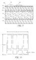
- FIG. 7 is a schematic showing the 5 ⁇ 5 sub-pixel make up of an 84 ⁇ 84 ⁇ m pixel.
- FIG. 8 is a schematic plan view of one cell arrangement useful in the invention.
- FIG. 9 is a schematic cross sectional view showing the separation of droplets.
- FIG. 10 is a schematic plan view of a second cell arrangement useful in the invention.
- FIG. 11 is a schematic plan view of a relatively large size cell useful in the invention.
- FIGS. 12A and 12B represent a plan view and front section along the line 12 B— 12 B, respectively, of a cell arrangement of the invention.
- FIGS. 13A and 13B represent a plan view and front section along the line 13 B— 13 B, respectively, of a further cell arrangement of the invention.
- FIGS. 14A-14I represent a sequential perspective view of a method of forming a four-cell segment of a media of the invention.
- FIG. 14J represents a perspective view, partially in section, showing the interconnection of the cells of the media segment of FIG. 14I to the rest of the media.
- the media of the present invention is different from conventional media in that it does not depend on ink diffusion or absorption by capillary action to avoid coalescence and color bleed. Instead the surface of the receiver is covered with a predetermined array of regular shaped reservoirs or cells that hold the fluid and keep it from communicating with adjacent drops. Such a cell array is shown in FIG. 3 and is formed on top of the conventional ink-jet paper shown in FIG. 1 .
- the term bonded is employed herein to generically indicate that successive layers or deposits form an integral structure, with or without an adhesion promoting material.
- FIG. 1 shows a prior art ink-jet media comprising a paper support 40 separated from backside anti-curl layer 60 by polyethylene resin film 50 .
- the paper support is coated with polyethylene resin film 30 , bottom swellable polymer containing mordant 20 and top swellable polymer containing mordant 10 .
- the polyethylene resin prevents the ink carrier fluid from entering the paper.
- FIG. 2 shows a similar prior art media to FIG. 1, comprised of polyethylene layers 550 and 530 sandwiched about paper support 540 and bearing image receiving layers 500 , 510 , and 520 .
- FIG. 3 shows the inventive embodiment corresponding to FIG. 1 in which the hydrophobic walls 90 of the cells 70 , are supported on the swellable polymer 10 . Recently deposited ink droplet 80 is contained in the cell.
- FIG. 4 shows an alternative architecture corresponding to FIG. 1 in which the hydrophobic walls 90 of the cells 70 are bonded to the polyethylene layer 30 .
- FIG. 5 shows the schematic cross section of FIG. 3 after fusing in which the hydrophobic walls have been converted to a protective layer 100 and ink droplet 80 has spread out during absorption.
- FIG. 6 shows the schematic cross section of FIG. 4 after fusing in which the hydrophobic walls have been converted to a protective layer 100 .
- the cells receive the ink from the print head and by the end of the printing cycle much of the ink still remains confined in the cells. The receiver is then moved to a holding area and kept there until most of the volatile portion of the ink evaporates. Because of the cell structure, the paper sheets can be stacked one on top of each other since the cell walls can serve as standoffs.
- the media may, after application of the ink, be subjected to elevated temperature and/or pressure e.g. via a heated roller that melts or fuses the walls of the cells.
- elevated temperature and/or pressure e.g. via a heated roller that melts or fuses the walls of the cells.
- This process gives the image a glossy finish and forms a continuous protective film, shown schematically in FIGS. 5 and 6, similar to what lamination accomplishes. This protects the image from water, air borne pollutants and abrasion damage and may offer UV or other protection for long colorant stability and image life.
- FIG. 6 the portions of the cell walls adjacent to the image-receiving layer are shown broken. This occurs during melting to allow colorant diffusion sideways for better image quality.
- the desired cell array, area, and volume depend on the desired final image quality. If it is assumed that the newest print head technology produces 1 pL drops, the drops are about 12 ⁇ m diameter spheres when in the air and produce an image of a circular disc on conventional ink jet papers of a diameter about 50% larger than their diameter in air. The increase depends on the drop velocity, how hydrophilic the surface is, and the rate of absorption of the fluid into the paper. Assume further that the colorant concentration in these drops is at the maximum value, that is, the disc formed on the paper results in an image that has maximum color saturation. For a secondary color, as discussed previously, two droplets are needed per site. Recall that the smallest spot size visible by the human eye is about 84 ⁇ 84 ⁇ m 2 .
- FIG. 7 shows a theoretical 84 ⁇ 84 ⁇ m 5 ⁇ 5 pixel array containing 25 sub-pixels 600 .
- FIG. 8 shows an array as in FIG. 7 comprised of the hydrophobic walls 610 and the hydrophilic ink absorbing area of subpixel 600 .
- FIG. 9 shows how the embodiment of FIG. 3 separates different colored ink drops 82 and 84 from each other.
- the hydrophobic film prevents the spreading of the fluid on the surface and thus contains the droplets within their corresponding subpixel, thus preventing coalescence.
- the line widths of the hydrophobic rings may vary from 1 to 10 ⁇ m and their height can vary from ⁇ 1 ⁇ m to >1 ⁇ m. However, since no ink stays on top of the hydrophobic areas, for full colorant area coverage, the ink will desirably diffuse under them from the adjacent hydrophilic regions. In the instances where the hydrophobic material is very thin, these rings cannot be melted in order to provide water, abrasion and UV protection for the image.
- the subpixels must be able to contain more than one or two droplets of ink. This is accomplished by increasing the heights of the subpixel walls thus increasing their volume or ink holding capacity. Note that as it was disclosed in U.S. Pat. No. 6,089,692 of Anagnostopoulos, the colorant concentration in the ink must now be 1 ⁇ 8 or less the saturation value. That is, it takes 8 droplets one on top of another of one primary color to achieve a fully saturated spot of that color on the paper. For a secondary color 16 droplets are required, 8 of each primary color.
- the advantages of the diluted ink are higher dynamic range within a single pixel and, in the low-density areas of a print, less grain or noise without the need for extra supplies of low colorant density inks.
- FIG. 10 is another schematic plan view of an array of cells 100 bordered by the hydrophobic walls 90 in which the cells are rectangular or square in shape.
- the subpixel size is drawn 21 ⁇ 21 ⁇ m 2 .
- the wall heights have to be about 28 ⁇ m to accommodate 8 pL of fluid or about 8,000 ⁇ m3 of fluid volume per pixel.
- the wall heights will have to be about 56 ⁇ m. This will give a maximum of 129 levels of gray per pixel, 16 subpixels ⁇ 8 levels of gray per subpixel equals 128.
- the null that is no ink in a subpixel, adds another level. As droplets are deposited within each subpixel evaporation and diffusion of the ink is taking place, thus these wall heights represent the worst case maximum they need to be.
- the cells on the paper may be placed in a predetermined pseudo-random pattern but not a regular grid arrangement as shown in FIG. 10 .
- the sub-pixels may be eliminated and the cell thus comprises the entire pixel, as shown in FIG. 11 .
- the cells must then have a fluid holding capacity of 128 pL per pixel for a saturated primary color spot and 256 pL for a secondary color spot. Assuming 21 ⁇ m thick walls, the wall heights have to be about 20 and 40 ⁇ m respectively. For these large area cells, attention should be given to the requirement that when the walls are melted at the end of the printing step they provide at least about a 2 ⁇ m thick protective film over each pixel on the paper. This condition is met for walls that are at least 20 ⁇ m high.
- FIGS. 14A-14J There are a number of ways to make the cells and a variety of materials that meet the requirements. The preferred way is demonstrated in FIGS. 14A-14J.
- the cells are formed on top of the ink jet paper 10 or on the polyethylene film 30 , such as shown in FIG. 9 or 13 .
- the process starts by wet roll or curtain coating of a thin first sol-gel 1 layer 200 (which may be, for example, an aqueous solution of a silica chemical species or metal alkoxides and water in an alcoholic solvent) and then drying of this coat at near room temperature, as shown in FIG. 14 B.
- the resulting gel is transparent and has the important property that it is not etched in oxygen plasma.
- a thick layer of a plastic film 210 is coated as shown in FIG.
- this film which eventually will form the cell walls.
- desired properties of this film are that it melts at a temperature below 100° C., forms a scratch resistant film after it cools, is impenetrable to water, air pollutants such as ozone and oils and can be doped with UV absorbers.
- a second sol-gel 2 layer 220 is then coated on top of the plastic layer as shown in FIG. 14D followed by a coating of photoresist 230 as shown in FIG. 14 E. This photoresist film is then exposed through a mask and developed forming the pattern shown in FIG. 14F with the protective photoresist removed.
- the top sol-gel layer is etched selectively in a plasma environment containing active fluorine ions that react with the Silicon in the sol-gel matrix forming volatile SiF 4 molecules, thus etching the layer.
- This removes the sol-gel in the desired areas above the plastic layer as shown in FIG. 14 G.
- the paper is subjected next to another plasma environment this one containing oxygen ions. This process etches the plastic film and photoresist but the sol-gel layer is not affected, thus serving as the mask.
- FIG. 14 G shows that the plastic film and photoresist but the sol-gel layer is not affected, thus serving as the mask.
- the cell walls and absorbent base are thereby formed. Then the fluorine plasma etch process is repeated to remove the sol-gel 2 film on top of the cell walls as well as the sol-gel 1 film on the base of the cells as shown in FIG. 14 I.
- the finished structure is shown schematically in FIG. 14 J.
- Suitable materials for the cell walls are hydrophobic polymers that are generally classified as either condensation polymers or addition polymers.
- Condensation polymers include, for example, polyesters, polyamides, polyurethanes, polyureas, polyethers, polycarbonates, polyacid anhydrides, and polymers comprising combinations of the above-mentioned types.
- Addition polymers are polymers formed from polymerization of vinyl-type monomers including, for example, allyl compounds, vinyl ethers, vinyl esters, vinyl heterocyclic compounds, styrenes, olefins and halogenated olefins, unsaturated acids and esters derived from them, unsaturated nitriles, vinyl alcohols, acrylamides and methacrylamides, vinyl ketones, multifunctional monomers, or copolymers formed from various combinations of these monomers.
- Preferred polymers may also comprise monomers which give hydrophilic homopolymers, if the overall polymer composition is sufficiently hydrophobic to channel the aqueous ink to the hydrophilic cell base. Further listings of suitable monomers for addition type polymers are found in U.S. Pat. No. 5,594,047 incorporated herein by reference.
- the cells are built on top of the polyethylene film that coats the paper base, in exactly the same way as described above. Then at the end of that process, the image receiving layers are coated over the cells and are allowed to settle into the bottom of the cells.
Landscapes
- Ink Jet Recording Methods And Recording Media Thereof (AREA)
- Ink Jet (AREA)
Abstract
Description
Claims (20)
Priority Applications (1)
| Application Number | Priority Date | Filing Date | Title |
|---|---|---|---|
| US10/046,024 US6638693B2 (en) | 2001-10-29 | 2001-10-29 | Process for making media for high quality ink jet printing |
Applications Claiming Priority (1)
| Application Number | Priority Date | Filing Date | Title |
|---|---|---|---|
| US10/046,024 US6638693B2 (en) | 2001-10-29 | 2001-10-29 | Process for making media for high quality ink jet printing |
Publications (2)
| Publication Number | Publication Date |
|---|---|
| US20030082353A1 US20030082353A1 (en) | 2003-05-01 |
| US6638693B2 true US6638693B2 (en) | 2003-10-28 |
Family
ID=21941168
Family Applications (1)
| Application Number | Title | Priority Date | Filing Date |
|---|---|---|---|
| US10/046,024 Expired - Fee Related US6638693B2 (en) | 2001-10-29 | 2001-10-29 | Process for making media for high quality ink jet printing |
Country Status (1)
| Country | Link |
|---|---|
| US (1) | US6638693B2 (en) |
Cited By (3)
| Publication number | Priority date | Publication date | Assignee | Title |
|---|---|---|---|---|
| US20050007434A1 (en) * | 2001-10-29 | 2005-01-13 | Anagnostopoulos Constantine N. | Receiver media for high quality ink jet printing |
| US20090162554A1 (en) * | 2007-12-21 | 2009-06-25 | Manico Joseph A | Method for using receiver medium having adjustable properties |
| US20090162120A1 (en) * | 2007-12-21 | 2009-06-25 | Manico Joseph A | Printer and printing method using receiver medium having adjustable properties |
Families Citing this family (1)
| Publication number | Priority date | Publication date | Assignee | Title |
|---|---|---|---|---|
| US7150901B2 (en) | 2003-12-05 | 2006-12-19 | Eastman Kodak Company | Plasma treatment of porous inkjet receivers |
Citations (4)
| Publication number | Priority date | Publication date | Assignee | Title |
|---|---|---|---|---|
| WO1999055537A1 (en) | 1998-04-29 | 1999-11-04 | 3M Innovative Properties Company | Receptor sheet for inkjet printing having an embossed surface |
| US6045917A (en) | 1998-07-10 | 2000-04-04 | Eastman Kodak Company | Ink jet recording element |
| WO2000073082A1 (en) | 1999-06-01 | 2000-12-07 | 3M Innovative Properties Company | Random microembossed receptor media |
| US6197482B1 (en) | 1999-05-14 | 2001-03-06 | Eastman Kodak Company | Polymer overcoat for imaging elements |
-
2001
- 2001-10-29 US US10/046,024 patent/US6638693B2/en not_active Expired - Fee Related
Patent Citations (4)
| Publication number | Priority date | Publication date | Assignee | Title |
|---|---|---|---|---|
| WO1999055537A1 (en) | 1998-04-29 | 1999-11-04 | 3M Innovative Properties Company | Receptor sheet for inkjet printing having an embossed surface |
| US6045917A (en) | 1998-07-10 | 2000-04-04 | Eastman Kodak Company | Ink jet recording element |
| US6197482B1 (en) | 1999-05-14 | 2001-03-06 | Eastman Kodak Company | Polymer overcoat for imaging elements |
| WO2000073082A1 (en) | 1999-06-01 | 2000-12-07 | 3M Innovative Properties Company | Random microembossed receptor media |
Non-Patent Citations (3)
| Title |
|---|
| Aidan Lavery, "Photomedia for Ink Jet Printing," Proceedings IS&Ts NIP 16: 2000, International Conference on Digital Printing Technologies, Vancouver Canada, Oct.16-20, 2000, pp 216-220. |
| Dieter Reichel and Willy Heinzelmann, "Anisotropic Porous Substrates for High Resolution Digital Images," Proceeding IS&Ts NIP 16: 2000 International Conference on Digital Printing Technologies, Vancouver Canada, Oct. 16-20, 2000, pp 204-207. |
| Kenzo Kasahara, "A New Quick-Drying, High-Water-Resistant Glossy Ink Jet Paper," Proceedings IS&T's NIP 14: 1998 International Conference on Digital Printing Technologies, Toronto, Canada, Oct. 18-23, 1998, pp 150-152. |
Cited By (5)
| Publication number | Priority date | Publication date | Assignee | Title |
|---|---|---|---|---|
| US20050007434A1 (en) * | 2001-10-29 | 2005-01-13 | Anagnostopoulos Constantine N. | Receiver media for high quality ink jet printing |
| US6984035B2 (en) * | 2001-10-29 | 2006-01-10 | Eastman Kodak Company | Receiver media for high quality ink jet printing |
| US20090162554A1 (en) * | 2007-12-21 | 2009-06-25 | Manico Joseph A | Method for using receiver medium having adjustable properties |
| US20090162120A1 (en) * | 2007-12-21 | 2009-06-25 | Manico Joseph A | Printer and printing method using receiver medium having adjustable properties |
| US7875314B2 (en) | 2007-12-21 | 2011-01-25 | Eastman Kodak Company | Method for using receiver medium having adjustable properties |
Also Published As
| Publication number | Publication date |
|---|---|
| US20030082353A1 (en) | 2003-05-01 |
Similar Documents
| Publication | Publication Date | Title |
|---|---|---|
| KR100550370B1 (en) | Coated microporous inkjet receptive media and method for controlling dot diameter | |
| US4642654A (en) | Recording method | |
| US6110601A (en) | Ink jet recording element | |
| EP1708892B1 (en) | Inkjet recording element | |
| US7232214B2 (en) | Method for increasing the diameter of an ink jet ink dot | |
| US6432550B1 (en) | Ink-jet recording sheet | |
| US6638693B2 (en) | Process for making media for high quality ink jet printing | |
| JP2006026905A (en) | Manufacturing method of inkjet recording paper and inkjet recording paper | |
| US6984035B2 (en) | Receiver media for high quality ink jet printing | |
| US7150901B2 (en) | Plasma treatment of porous inkjet receivers | |
| US6695447B1 (en) | Ink jet recording element | |
| EP1403089B1 (en) | Ink jet recording element and printing method | |
| US20030082351A1 (en) | Receiver media for high quality ink jet printing | |
| US6846526B2 (en) | Ink jet recording element | |
| US6380280B1 (en) | Ink jet recording element | |
| US6814437B2 (en) | Ink jet printing method | |
| US6921562B2 (en) | Ink jet recording element | |
| US6457825B1 (en) | Ink jet printing method | |
| JP2749814B2 (en) | Inkjet recording method | |
| JP2000158804A (en) | Recording medium, ink-jet recording method and image- forming method using the same | |
| JP2005169643A (en) | Inkjet recording medium and inkjet recording method | |
| JP3669314B2 (en) | Inkjet recording method | |
| US20030099822A1 (en) | Ink jet recording media and method for their production | |
| JP2005199637A (en) | Inkjet recording medium, manufacturing method therefor, and inkjet recording method | |
| JPH0255186A (en) | Material to be recorded |
Legal Events
| Date | Code | Title | Description |
|---|---|---|---|
| AS | Assignment |
Owner name: EASTMAN KODAK COMPANY, NEW YORK Free format text: ASSIGNMENT OF ASSIGNORS INTEREST;ASSIGNORS:ANAGNOSTOPOULOS, CONSTANTINE N.;DOKYI, EMMANUEL K.;SHARMA, RAVI;AND OTHERS;REEL/FRAME:013771/0241 Effective date: 20011029 |
|
| FEPP | Fee payment procedure |
Free format text: PAYOR NUMBER ASSIGNED (ORIGINAL EVENT CODE: ASPN); ENTITY STATUS OF PATENT OWNER: LARGE ENTITY |
|
| FPAY | Fee payment |
Year of fee payment: 4 |
|
| FPAY | Fee payment |
Year of fee payment: 8 |
|
| AS | Assignment |
Owner name: CITICORP NORTH AMERICA, INC., AS AGENT, NEW YORK Free format text: SECURITY INTEREST;ASSIGNORS:EASTMAN KODAK COMPANY;PAKON, INC.;REEL/FRAME:028201/0420 Effective date: 20120215 |
|
| AS | Assignment |
Owner name: WILMINGTON TRUST, NATIONAL ASSOCIATION, AS AGENT, Free format text: PATENT SECURITY AGREEMENT;ASSIGNORS:EASTMAN KODAK COMPANY;PAKON, INC.;REEL/FRAME:030122/0235 Effective date: 20130322 Owner name: WILMINGTON TRUST, NATIONAL ASSOCIATION, AS AGENT, MINNESOTA Free format text: PATENT SECURITY AGREEMENT;ASSIGNORS:EASTMAN KODAK COMPANY;PAKON, INC.;REEL/FRAME:030122/0235 Effective date: 20130322 |
|
| AS | Assignment |
Owner name: BANK OF AMERICA N.A., AS AGENT, MASSACHUSETTS Free format text: INTELLECTUAL PROPERTY SECURITY AGREEMENT (ABL);ASSIGNORS:EASTMAN KODAK COMPANY;FAR EAST DEVELOPMENT LTD.;FPC INC.;AND OTHERS;REEL/FRAME:031162/0117 Effective date: 20130903 Owner name: BARCLAYS BANK PLC, AS ADMINISTRATIVE AGENT, NEW YORK Free format text: INTELLECTUAL PROPERTY SECURITY AGREEMENT (SECOND LIEN);ASSIGNORS:EASTMAN KODAK COMPANY;FAR EAST DEVELOPMENT LTD.;FPC INC.;AND OTHERS;REEL/FRAME:031159/0001 Effective date: 20130903 Owner name: JPMORGAN CHASE BANK, N.A., AS ADMINISTRATIVE, DELAWARE Free format text: INTELLECTUAL PROPERTY SECURITY AGREEMENT (FIRST LIEN);ASSIGNORS:EASTMAN KODAK COMPANY;FAR EAST DEVELOPMENT LTD.;FPC INC.;AND OTHERS;REEL/FRAME:031158/0001 Effective date: 20130903 Owner name: EASTMAN KODAK COMPANY, NEW YORK Free format text: RELEASE OF SECURITY INTEREST IN PATENTS;ASSIGNORS:CITICORP NORTH AMERICA, INC., AS SENIOR DIP AGENT;WILMINGTON TRUST, NATIONAL ASSOCIATION, AS JUNIOR DIP AGENT;REEL/FRAME:031157/0451 Effective date: 20130903 Owner name: PAKON, INC., NEW YORK Free format text: RELEASE OF SECURITY INTEREST IN PATENTS;ASSIGNORS:CITICORP NORTH AMERICA, INC., AS SENIOR DIP AGENT;WILMINGTON TRUST, NATIONAL ASSOCIATION, AS JUNIOR DIP AGENT;REEL/FRAME:031157/0451 Effective date: 20130903 Owner name: JPMORGAN CHASE BANK, N.A., AS ADMINISTRATIVE, DELA Free format text: INTELLECTUAL PROPERTY SECURITY AGREEMENT (FIRST LIEN);ASSIGNORS:EASTMAN KODAK COMPANY;FAR EAST DEVELOPMENT LTD.;FPC INC.;AND OTHERS;REEL/FRAME:031158/0001 Effective date: 20130903 Owner name: BARCLAYS BANK PLC, AS ADMINISTRATIVE AGENT, NEW YO Free format text: INTELLECTUAL PROPERTY SECURITY AGREEMENT (SECOND LIEN);ASSIGNORS:EASTMAN KODAK COMPANY;FAR EAST DEVELOPMENT LTD.;FPC INC.;AND OTHERS;REEL/FRAME:031159/0001 Effective date: 20130903 |
|
| REMI | Maintenance fee reminder mailed | ||
| LAPS | Lapse for failure to pay maintenance fees | ||
| STCH | Information on status: patent discontinuation |
Free format text: PATENT EXPIRED DUE TO NONPAYMENT OF MAINTENANCE FEES UNDER 37 CFR 1.362 |
|
| FP | Lapsed due to failure to pay maintenance fee |
Effective date: 20151028 |
|
| AS | Assignment |
Owner name: KODAK AVIATION LEASING LLC, NEW YORK Free format text: RELEASE BY SECURED PARTY;ASSIGNOR:JP MORGAN CHASE BANK, N.A., AS ADMINISTRATIVE AGENT;REEL/FRAME:049814/0001 Effective date: 20190617 Owner name: NPEC, INC., NEW YORK Free format text: RELEASE BY SECURED PARTY;ASSIGNOR:JP MORGAN CHASE BANK, N.A., AS ADMINISTRATIVE AGENT;REEL/FRAME:049814/0001 Effective date: 20190617 Owner name: FPC, INC., NEW YORK Free format text: RELEASE BY SECURED PARTY;ASSIGNOR:JP MORGAN CHASE BANK, N.A., AS ADMINISTRATIVE AGENT;REEL/FRAME:049814/0001 Effective date: 20190617 Owner name: CREO MANUFACTURING AMERICA LLC, NEW YORK Free format text: RELEASE BY SECURED PARTY;ASSIGNOR:JP MORGAN CHASE BANK, N.A., AS ADMINISTRATIVE AGENT;REEL/FRAME:049814/0001 Effective date: 20190617 Owner name: KODAK AMERICAS, LTD., NEW YORK Free format text: RELEASE BY SECURED PARTY;ASSIGNOR:JP MORGAN CHASE BANK, N.A., AS ADMINISTRATIVE AGENT;REEL/FRAME:049814/0001 Effective date: 20190617 Owner name: KODAK REALTY, INC., NEW YORK Free format text: RELEASE BY SECURED PARTY;ASSIGNOR:JP MORGAN CHASE BANK, N.A., AS ADMINISTRATIVE AGENT;REEL/FRAME:049814/0001 Effective date: 20190617 Owner name: KODAK PORTUGUESA LIMITED, NEW YORK Free format text: RELEASE BY SECURED PARTY;ASSIGNOR:JP MORGAN CHASE BANK, N.A., AS ADMINISTRATIVE AGENT;REEL/FRAME:049814/0001 Effective date: 20190617 Owner name: KODAK PHILIPPINES, LTD., NEW YORK Free format text: RELEASE BY SECURED PARTY;ASSIGNOR:JP MORGAN CHASE BANK, N.A., AS ADMINISTRATIVE AGENT;REEL/FRAME:049814/0001 Effective date: 20190617 Owner name: EASTMAN KODAK COMPANY, NEW YORK Free format text: RELEASE BY SECURED PARTY;ASSIGNOR:JP MORGAN CHASE BANK, N.A., AS ADMINISTRATIVE AGENT;REEL/FRAME:049814/0001 Effective date: 20190617 Owner name: KODAK IMAGING NETWORK, INC., NEW YORK Free format text: RELEASE BY SECURED PARTY;ASSIGNOR:JP MORGAN CHASE BANK, N.A., AS ADMINISTRATIVE AGENT;REEL/FRAME:049814/0001 Effective date: 20190617 Owner name: PAKON, INC., NEW YORK Free format text: RELEASE BY SECURED PARTY;ASSIGNOR:JP MORGAN CHASE BANK, N.A., AS ADMINISTRATIVE AGENT;REEL/FRAME:049814/0001 Effective date: 20190617 Owner name: LASER PACIFIC MEDIA CORPORATION, NEW YORK Free format text: RELEASE BY SECURED PARTY;ASSIGNOR:JP MORGAN CHASE BANK, N.A., AS ADMINISTRATIVE AGENT;REEL/FRAME:049814/0001 Effective date: 20190617 Owner name: FAR EAST DEVELOPMENT LTD., NEW YORK Free format text: RELEASE BY SECURED PARTY;ASSIGNOR:JP MORGAN CHASE BANK, N.A., AS ADMINISTRATIVE AGENT;REEL/FRAME:049814/0001 Effective date: 20190617 Owner name: QUALEX, INC., NEW YORK Free format text: RELEASE BY SECURED PARTY;ASSIGNOR:JP MORGAN CHASE BANK, N.A., AS ADMINISTRATIVE AGENT;REEL/FRAME:049814/0001 Effective date: 20190617 Owner name: KODAK (NEAR EAST), INC., NEW YORK Free format text: RELEASE BY SECURED PARTY;ASSIGNOR:JP MORGAN CHASE BANK, N.A., AS ADMINISTRATIVE AGENT;REEL/FRAME:049814/0001 Effective date: 20190617 |
|
| AS | Assignment |
Owner name: NPEC INC., NEW YORK Free format text: RELEASE BY SECURED PARTY;ASSIGNOR:BARCLAYS BANK PLC;REEL/FRAME:052773/0001 Effective date: 20170202 Owner name: QUALEX INC., NEW YORK Free format text: RELEASE BY SECURED PARTY;ASSIGNOR:BARCLAYS BANK PLC;REEL/FRAME:052773/0001 Effective date: 20170202 Owner name: KODAK REALTY INC., NEW YORK Free format text: RELEASE BY SECURED PARTY;ASSIGNOR:BARCLAYS BANK PLC;REEL/FRAME:052773/0001 Effective date: 20170202 Owner name: FPC INC., NEW YORK Free format text: RELEASE BY SECURED PARTY;ASSIGNOR:BARCLAYS BANK PLC;REEL/FRAME:052773/0001 Effective date: 20170202 Owner name: LASER PACIFIC MEDIA CORPORATION, NEW YORK Free format text: RELEASE BY SECURED PARTY;ASSIGNOR:BARCLAYS BANK PLC;REEL/FRAME:052773/0001 Effective date: 20170202 Owner name: FAR EAST DEVELOPMENT LTD., NEW YORK Free format text: RELEASE BY SECURED PARTY;ASSIGNOR:BARCLAYS BANK PLC;REEL/FRAME:052773/0001 Effective date: 20170202 Owner name: KODAK AMERICAS LTD., NEW YORK Free format text: RELEASE BY SECURED PARTY;ASSIGNOR:BARCLAYS BANK PLC;REEL/FRAME:052773/0001 Effective date: 20170202 Owner name: KODAK PHILIPPINES LTD., NEW YORK Free format text: RELEASE BY SECURED PARTY;ASSIGNOR:BARCLAYS BANK PLC;REEL/FRAME:052773/0001 Effective date: 20170202 Owner name: KODAK (NEAR EAST) INC., NEW YORK Free format text: RELEASE BY SECURED PARTY;ASSIGNOR:BARCLAYS BANK PLC;REEL/FRAME:052773/0001 Effective date: 20170202 Owner name: EASTMAN KODAK COMPANY, NEW YORK Free format text: RELEASE BY SECURED PARTY;ASSIGNOR:BARCLAYS BANK PLC;REEL/FRAME:052773/0001 Effective date: 20170202 |