US6638025B2 - Method and apparatus for controlling a fluid actuated system - Google Patents
Method and apparatus for controlling a fluid actuated system Download PDFInfo
- Publication number
- US6638025B2 US6638025B2 US10/020,145 US2014501A US6638025B2 US 6638025 B2 US6638025 B2 US 6638025B2 US 2014501 A US2014501 A US 2014501A US 6638025 B2 US6638025 B2 US 6638025B2
- Authority
- US
- United States
- Prior art keywords
- fluid
- signal
- actuator
- pressure
- pump
- Prior art date
- Legal status (The legal status is an assumption and is not a legal conclusion. Google has not performed a legal analysis and makes no representation as to the accuracy of the status listed.)
- Expired - Fee Related, expires
Links
Images


Classifications
-
- F—MECHANICAL ENGINEERING; LIGHTING; HEATING; WEAPONS; BLASTING
- F02—COMBUSTION ENGINES; HOT-GAS OR COMBUSTION-PRODUCT ENGINE PLANTS
- F02D—CONTROLLING COMBUSTION ENGINES
- F02D41/00—Electrical control of supply of combustible mixture or its constituents
- F02D41/30—Controlling fuel injection
- F02D41/38—Controlling fuel injection of the high pressure type
- F02D41/3809—Common rail control systems
- F02D41/3836—Controlling the fuel pressure
- F02D41/3845—Controlling the fuel pressure by controlling the flow into the common rail, e.g. the amount of fuel pumped
-
- F—MECHANICAL ENGINEERING; LIGHTING; HEATING; WEAPONS; BLASTING
- F02—COMBUSTION ENGINES; HOT-GAS OR COMBUSTION-PRODUCT ENGINE PLANTS
- F02D—CONTROLLING COMBUSTION ENGINES
- F02D41/00—Electrical control of supply of combustible mixture or its constituents
- F02D41/30—Controlling fuel injection
- F02D41/3082—Control of electrical fuel pumps
-
- F—MECHANICAL ENGINEERING; LIGHTING; HEATING; WEAPONS; BLASTING
- F02—COMBUSTION ENGINES; HOT-GAS OR COMBUSTION-PRODUCT ENGINE PLANTS
- F02M—SUPPLYING COMBUSTION ENGINES IN GENERAL WITH COMBUSTIBLE MIXTURES OR CONSTITUENTS THEREOF
- F02M39/00—Arrangements of fuel-injection apparatus with respect to engines; Pump drives adapted to such arrangements
- F02M39/02—Arrangements of fuel-injection apparatus to facilitate the driving of pumps; Arrangements of fuel-injection pumps; Pump drives
-
- F—MECHANICAL ENGINEERING; LIGHTING; HEATING; WEAPONS; BLASTING
- F02—COMBUSTION ENGINES; HOT-GAS OR COMBUSTION-PRODUCT ENGINE PLANTS
- F02M—SUPPLYING COMBUSTION ENGINES IN GENERAL WITH COMBUSTIBLE MIXTURES OR CONSTITUENTS THEREOF
- F02M47/00—Fuel-injection apparatus operated cyclically with fuel-injection valves actuated by fluid pressure
-
- F—MECHANICAL ENGINEERING; LIGHTING; HEATING; WEAPONS; BLASTING
- F02—COMBUSTION ENGINES; HOT-GAS OR COMBUSTION-PRODUCT ENGINE PLANTS
- F02M—SUPPLYING COMBUSTION ENGINES IN GENERAL WITH COMBUSTIBLE MIXTURES OR CONSTITUENTS THEREOF
- F02M57/00—Fuel-injectors combined or associated with other devices
- F02M57/02—Injectors structurally combined with fuel-injection pumps
- F02M57/022—Injectors structurally combined with fuel-injection pumps characterised by the pump drive
- F02M57/025—Injectors structurally combined with fuel-injection pumps characterised by the pump drive hydraulic, e.g. with pressure amplification
-
- F—MECHANICAL ENGINEERING; LIGHTING; HEATING; WEAPONS; BLASTING
- F02—COMBUSTION ENGINES; HOT-GAS OR COMBUSTION-PRODUCT ENGINE PLANTS
- F02M—SUPPLYING COMBUSTION ENGINES IN GENERAL WITH COMBUSTIBLE MIXTURES OR CONSTITUENTS THEREOF
- F02M59/00—Pumps specially adapted for fuel-injection and not provided for in groups F02M39/00 -F02M57/00, e.g. rotary cylinder-block type of pumps
- F02M59/02—Pumps specially adapted for fuel-injection and not provided for in groups F02M39/00 -F02M57/00, e.g. rotary cylinder-block type of pumps of reciprocating-piston or reciprocating-cylinder type
- F02M59/04—Pumps specially adapted for fuel-injection and not provided for in groups F02M39/00 -F02M57/00, e.g. rotary cylinder-block type of pumps of reciprocating-piston or reciprocating-cylinder type characterised by special arrangement of cylinders with respect to piston-driving shaft, e.g. arranged parallel to that shaft or swash-plate type pumps
-
- F—MECHANICAL ENGINEERING; LIGHTING; HEATING; WEAPONS; BLASTING
- F04—POSITIVE - DISPLACEMENT MACHINES FOR LIQUIDS; PUMPS FOR LIQUIDS OR ELASTIC FLUIDS
- F04B—POSITIVE-DISPLACEMENT MACHINES FOR LIQUIDS; PUMPS
- F04B1/00—Multi-cylinder machines or pumps characterised by number or arrangement of cylinders
- F04B1/12—Multi-cylinder machines or pumps characterised by number or arrangement of cylinders having cylinder axes coaxial with, or parallel or inclined to, main shaft axis
- F04B1/26—Control
- F04B1/28—Control of machines or pumps with stationary cylinders
-
- F—MECHANICAL ENGINEERING; LIGHTING; HEATING; WEAPONS; BLASTING
- F02—COMBUSTION ENGINES; HOT-GAS OR COMBUSTION-PRODUCT ENGINE PLANTS
- F02D—CONTROLLING COMBUSTION ENGINES
- F02D2200/00—Input parameters for engine control
- F02D2200/02—Input parameters for engine control the parameters being related to the engine
- F02D2200/06—Fuel or fuel supply system parameters
- F02D2200/0602—Fuel pressure
-
- F—MECHANICAL ENGINEERING; LIGHTING; HEATING; WEAPONS; BLASTING
- F02—COMBUSTION ENGINES; HOT-GAS OR COMBUSTION-PRODUCT ENGINE PLANTS
- F02D—CONTROLLING COMBUSTION ENGINES
- F02D2200/00—Input parameters for engine control
- F02D2200/02—Input parameters for engine control the parameters being related to the engine
- F02D2200/06—Fuel or fuel supply system parameters
- F02D2200/0606—Fuel temperature
-
- F—MECHANICAL ENGINEERING; LIGHTING; HEATING; WEAPONS; BLASTING
- F02—COMBUSTION ENGINES; HOT-GAS OR COMBUSTION-PRODUCT ENGINE PLANTS
- F02D—CONTROLLING COMBUSTION ENGINES
- F02D2250/00—Engine control related to specific problems or objectives
- F02D2250/31—Control of the fuel pressure
-
- F—MECHANICAL ENGINEERING; LIGHTING; HEATING; WEAPONS; BLASTING
- F04—POSITIVE - DISPLACEMENT MACHINES FOR LIQUIDS; PUMPS FOR LIQUIDS OR ELASTIC FLUIDS
- F04B—POSITIVE-DISPLACEMENT MACHINES FOR LIQUIDS; PUMPS
- F04B2205/00—Fluid parameters
- F04B2205/05—Pressure after the pump outlet
Definitions
- the present invention relates generally to a hydraulically-actuated system, and more specifically to a fluid pump having a position sensor adapted to sense actuator position.
- U.S. Pat. No. 6,035,828 to Anderson et al. describes a system having a variable delivery fluid pump.
- the pump supplies fluid to a hydraulically-actuated fuel injection system.
- the pump outlet supplies high pressure lubrication oil to a plurality of hydraulically-actuated fuel injectors of a diesel engine.
- the pump is driven directly by the engine, and pump output is varied by an electronically controlled actuator.
- a pressure sensor is provided in the system that monitors the actual fluid pressure within the system.
- An electronic control module monitors fluid pressure and a number of engine operating parameters to determine if actual fluid pressure is sufficient for current engine operating conditions. To minimize the output of emissions of the engine, precise control of fluid pressure is critical.
- the pump may overshoot or undershoot desired system pressure. Even very small differences in actual pressure and desired pressure can adversely impact emissions and engine efficiency.
- the present invention is directed to overcoming one or more of the above identified problems.
- a fluid actuated system in one aspect of the present invention includes a variable delivery pump having a piston and a high pressure conduit.
- An actuator having a plunger and a position sensor adapted to deliver a position signal are connected to the pump.
- a fluid pressure sensor is connected to the high pressure outlet and adapted to deliver a signal related to a fluid pressure.
- An electronic control module is adapted to receive the pressure and position signals and send a directional control signal.
- a method of controlling a fluid pump includes the steps of sensing the pressure fluid in a high pressure conduit, sensing the position of an actuator and delivering a position related signal and delivering a directional move signal in response to the pressure signal and the position signal.
- FIG. 1 is a schematic illustration of a hydraulically-actuated system according to the present invention.
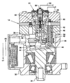
- FIG. 2 is a sectioned side diagrammatic view of a fixed displacement variable delivery pump according to one aspect of the present invention.
- a hydraulically actuated system 10 is attached to an internal combustion engine 12 .
- the hydraulically actuated system 10 includes a high pressure rail 14 that supplies high pressure actuation fluid to a plurality of hydraulically-actuated devices, such as hydraulically actuated fuel injectors 16 .
- a high pressure rail 14 is pressurized by a variable output fluid pump 18 via a high pressure supply conduit 22 .
- the pump 18 draws actuation fluid along a low pressure supply conduit 24 from a source of low pressure fluid, preferably the engine's lubricating oil sump 26 .
- the present invention preferably uses engine lubrication oil as its hydraulic medium.
- Typical variable delivery pumps include a pump housing 32 and a rotating shaft 34 positioned within the housing 32 .
- the rotating shaft 34 is coupled to the engine 12 , such that rotation of the engine 12 crank shaft (not shown) causes rotation of the pump shaft 34 .
- An angled swash plate 36 is attached to the rotating shaft 34 and causes a plurality of parallel disposed pistons 38 to reciprocate in a first direction d 1 and a second direction d 2 , opposite the first direction d 1 .
- the pump 18 includes five pistons 38 that are urged in the first direction d 1 , (toward the swash plate 36 ) by return springs 42 .
- Each piston 38 includes a shoe 44 that maintains contact with the swash plate 36 .
- Fluid pressure in the high pressure rail 14 is controlled by an actuator 51 that is controlled by an electronic control module 52 .
- An electrical control line 53 provides communication between the actuator 51 and the electronic control module 52 .
- the fixed displacement variable delivery pump 18 is illustrated in FIG. 2 .
- the fixed displacement variable delivery pump 18 includes a fixed angle swash plate 36 rotatably disposed within the pump housing 32 .
- Each piston 38 includes a spill port 54 extending from the piston cavity 48 to the low pressure portion 46 of the pump 18 .
- a sleeve 56 is slidably positioned over each piston 38 and coupled to the actuator 51 .
- the actuator 51 is moveable between a first position and a second position. The first position being related to fluid output at maximum, and the second position being related to fluid output minimum.
- the actuator 51 being in the second position, the spill ports 54 are uncovered, movement of the piston 38 in the second direction d 2 causes fluid to spill back into the low pressure portion 46 of the pump 18 .
- the actuator 51 being in the first position, the spill ports 54 are covered, movement of the piston in the second direction d 2 , causes fluid to be pushed out of the piston cavity 48 past a check valve 50 and into the high pressure rail 14 .
- variable displacement pump (not shown), is similar to the fixed displacement variable delivery pump, but uses a variable angle swash plate 36 to control fluid output.
- the variable angle swash plate 36 pivots about a central axis and is connected to the actuator 51 .
- the actuator 51 is connected is controlled by the electronic control module 52 to change the swash plate 36 angle.
- the swash plate 36 angle controls the distance that each piston 38 moves. Reducing the distance reduces pump 18 output and increasing the distance increases pump 18 output.
- the actuator 51 may be of typical construction, including hydraulic, electronic, or electro-hydraulic as illustrated in FIG. 2.
- a position sensor 58 is disposed on or near the actuator 51 .
- the position sensor 58 is adapted to sense the distance of the actuator 51 from a predetermined position and deliver a distance signal to the electronic control module 52 via a first communication line 59 .
- the actuator 51 is biased toward the second position by a spring 60 .
- the actuator 51 position may be infinitely varied between the first and second position.
- the position sensor 58 as illustrated is an ultrasonic position sensor.
- the ultrasonic position sensor 58 sends a signal toward a target and receives the signal after it is reflected off of the target. The amount of time required to receive the reflected signal is used to determine position. Numerous other position sensors 58 may be substituted including, hall effect, inductive and linear variable differential transformers.
- the desired pressure in the high pressure rail 14 is generally a function of the engine's operating condition. For instance, at high speeds and loads, the rail pressure is generally desired to be significantly higher that the desired rail pressure when the engine 12 is operating at an idle condition. For example, the desired rail pressure may vary from 4 mega-pascal at idle to 30 mega-pascal at full load.
- An operating condition sensor 62 is attached to an electronic control module 52 via a second communication line 66 .
- the operating condition sensor 62 provides the electronic control module 52 data, which includes engine speed and load conditions.
- a pressure sensor 68 periodically provides the electronic control module 52 with the actual fluid pressure in the high pressure rail 14 via a third communication line 72 .
- the electronic control module 52 compares a desired rail pressure, which is a function of engine operating condition, with the actual rail pressure provided by pressure sensor 68 .
- a temperature sensor 76 may additionally be connected to the fluid actuated system 10 , preferably between the pump and drain passage 28 .
- the temperature sensor 76 is adapted to provide data related to fluid temperature to the electronic control module 52 via a fourth communication line 78 .
- the temperature sensor 76 is also of typical construction and will not be discussed in detail.
- the temperature sensor 76 as with all other sensors, may provide either an analog or digital signal.
- the electronic control module 52 monitors the pressure sensor 68 , operating condition sensor 62 , position sensor 58 and the temperature sensor 76 . If the desired and actual rail pressures are different, the electronic control module 52 further evaluates the position of the actuator 51 . If desired pressure is above actual pressure and the actuator 51 is at the first position, the electronic control module 52 maintains actuator 51 position. If the desired pressure is above actual and the actuator 51 is between the first and second position, the electronic control module 52 sends a control signal to the actuator 51 to cause movement toward the first position.
- the electronic control module 52 sends a move signal to the actuator 51 commanding movement toward the second position. If the desired pressure is below actual and the actuator 51 is at the second position, the electronic control module 52 maintains actuator 51 position.
- the electronic control module 52 may be programmed with a number of maps.
- the maps can be created through experimentation and relate to a number of variables of the fluid actuated system 10 . Examples of maps that may be desirable are hereafter described. (1) Change in rail pressure related to actuator position and engine/pump speed. (2) Change in fluid pressure related to rate of actuator movement. (3) Rate of actuator movement related fluid temperature. (4) Fluid viscosity related to fluid temperature and rate of actuator movement. A number of other maps using position and temperature data may be utilized to more accurately control the fluid actuated system 10 .
Landscapes
- Engineering & Computer Science (AREA)
- Mechanical Engineering (AREA)
- General Engineering & Computer Science (AREA)
- Chemical & Material Sciences (AREA)
- Combustion & Propulsion (AREA)
- Physics & Mathematics (AREA)
- Fluid Mechanics (AREA)
- Electrical Control Of Air Or Fuel Supplied To Internal-Combustion Engine (AREA)
- Fuel-Injection Apparatus (AREA)
Abstract
Description
Claims (16)
Priority Applications (2)
| Application Number | Priority Date | Filing Date | Title |
|---|---|---|---|
| US10/020,145 US6638025B2 (en) | 2001-12-14 | 2001-12-14 | Method and apparatus for controlling a fluid actuated system |
| EP02024106A EP1319820A2 (en) | 2001-12-14 | 2002-10-29 | Method and apparatus for controlling a fluid actuated system |
Applications Claiming Priority (1)
| Application Number | Priority Date | Filing Date | Title |
|---|---|---|---|
| US10/020,145 US6638025B2 (en) | 2001-12-14 | 2001-12-14 | Method and apparatus for controlling a fluid actuated system |
Publications (2)
| Publication Number | Publication Date |
|---|---|
| US20030113210A1 US20030113210A1 (en) | 2003-06-19 |
| US6638025B2 true US6638025B2 (en) | 2003-10-28 |
Family
ID=21796994
Family Applications (1)
| Application Number | Title | Priority Date | Filing Date |
|---|---|---|---|
| US10/020,145 Expired - Fee Related US6638025B2 (en) | 2001-12-14 | 2001-12-14 | Method and apparatus for controlling a fluid actuated system |
Country Status (2)
| Country | Link |
|---|---|
| US (1) | US6638025B2 (en) |
| EP (1) | EP1319820A2 (en) |
Cited By (4)
| Publication number | Priority date | Publication date | Assignee | Title |
|---|---|---|---|---|
| US20050175442A1 (en) * | 2004-02-11 | 2005-08-11 | George Kadlicko | Housing for rotary hydraulic machines |
| US20070030009A1 (en) * | 2005-04-08 | 2007-02-08 | Siemens Aktiengesellschaft | Sensor for measuring the position of an actuating element |
| US20080202112A1 (en) * | 2007-02-28 | 2008-08-28 | Caterpillar Inc. | Method and system for feedback pressure control |
| US20120006289A1 (en) * | 2010-05-17 | 2012-01-12 | Schaeffler Technologies Gmbh & Co. Kg | Method and control device for determining a characteristic viscosity variable of an oil |
Families Citing this family (2)
| Publication number | Priority date | Publication date | Assignee | Title |
|---|---|---|---|---|
| DE102004034865A1 (en) | 2004-07-19 | 2006-02-16 | Siemens Ag | Sensor for measuring the position of an actuator |
| DE102005004570A1 (en) * | 2005-02-01 | 2006-08-10 | Robert Bosch Gmbh | Fuel injection system for internal combustion engines |
Citations (14)
| Publication number | Priority date | Publication date | Assignee | Title |
|---|---|---|---|---|
| US4381750A (en) * | 1980-07-24 | 1983-05-03 | Diesel Kiki Co., Ltd. | Fuel injection apparatus for internal combustion engines |
| US4711216A (en) * | 1985-05-16 | 1987-12-08 | Nippon Soken, Inc. | Fuel supply device for an internal combustion engine |
| US4934143A (en) | 1987-04-29 | 1990-06-19 | Vickers, Incorporated | Electrohydraulic fluid control system for variable displacement pump |
| US5121730A (en) * | 1991-10-11 | 1992-06-16 | Caterpillar Inc. | Methods of conditioning fluid in an electronically-controlled unit injector for starting |
| US5305681A (en) * | 1992-01-15 | 1994-04-26 | Caterpillar Inc. | Hydraulic control apparatus |
| US5357912A (en) * | 1993-02-26 | 1994-10-25 | Caterpillar Inc. | Electronic control system and method for a hydraulically-actuated fuel injection system |
| US5423302A (en) * | 1994-03-23 | 1995-06-13 | Caterpillar Inc. | Fuel injection control system having actuating fluid viscosity feedback |
| US5485820A (en) * | 1994-09-02 | 1996-01-23 | Navistar International Transportation Corp. | Injection control pressure strategy |
| US5515829A (en) * | 1994-05-20 | 1996-05-14 | Caterpillar Inc. | Variable-displacement actuating fluid pump for a HEUI fuel system |
| US5740782A (en) * | 1996-05-20 | 1998-04-21 | Lowi, Jr.; Alvin | Positive-displacement-metering, electro-hydraulic fuel injection system |
| US6035828A (en) * | 1998-03-11 | 2000-03-14 | Caterpillar Inc. | Hydraulically-actuated system having a variable delivery fixed displacement pump |
| US6227167B1 (en) | 2000-04-20 | 2001-05-08 | Mannesmann Rexroth Corporation | Suction controlled pump for HEUI systems |
| US6267561B1 (en) | 1999-03-16 | 2001-07-31 | Caterpillar Inc. | Variable delivery, fixed displacement pump |
| US6497223B1 (en) * | 2000-05-04 | 2002-12-24 | Cummins, Inc. | Fuel injection pressure control system for an internal combustion engine |
-
2001
- 2001-12-14 US US10/020,145 patent/US6638025B2/en not_active Expired - Fee Related
-
2002
- 2002-10-29 EP EP02024106A patent/EP1319820A2/en not_active Withdrawn
Patent Citations (14)
| Publication number | Priority date | Publication date | Assignee | Title |
|---|---|---|---|---|
| US4381750A (en) * | 1980-07-24 | 1983-05-03 | Diesel Kiki Co., Ltd. | Fuel injection apparatus for internal combustion engines |
| US4711216A (en) * | 1985-05-16 | 1987-12-08 | Nippon Soken, Inc. | Fuel supply device for an internal combustion engine |
| US4934143A (en) | 1987-04-29 | 1990-06-19 | Vickers, Incorporated | Electrohydraulic fluid control system for variable displacement pump |
| US5121730A (en) * | 1991-10-11 | 1992-06-16 | Caterpillar Inc. | Methods of conditioning fluid in an electronically-controlled unit injector for starting |
| US5305681A (en) * | 1992-01-15 | 1994-04-26 | Caterpillar Inc. | Hydraulic control apparatus |
| US5357912A (en) * | 1993-02-26 | 1994-10-25 | Caterpillar Inc. | Electronic control system and method for a hydraulically-actuated fuel injection system |
| US5423302A (en) * | 1994-03-23 | 1995-06-13 | Caterpillar Inc. | Fuel injection control system having actuating fluid viscosity feedback |
| US5515829A (en) * | 1994-05-20 | 1996-05-14 | Caterpillar Inc. | Variable-displacement actuating fluid pump for a HEUI fuel system |
| US5485820A (en) * | 1994-09-02 | 1996-01-23 | Navistar International Transportation Corp. | Injection control pressure strategy |
| US5740782A (en) * | 1996-05-20 | 1998-04-21 | Lowi, Jr.; Alvin | Positive-displacement-metering, electro-hydraulic fuel injection system |
| US6035828A (en) * | 1998-03-11 | 2000-03-14 | Caterpillar Inc. | Hydraulically-actuated system having a variable delivery fixed displacement pump |
| US6267561B1 (en) | 1999-03-16 | 2001-07-31 | Caterpillar Inc. | Variable delivery, fixed displacement pump |
| US6227167B1 (en) | 2000-04-20 | 2001-05-08 | Mannesmann Rexroth Corporation | Suction controlled pump for HEUI systems |
| US6497223B1 (en) * | 2000-05-04 | 2002-12-24 | Cummins, Inc. | Fuel injection pressure control system for an internal combustion engine |
Cited By (7)
| Publication number | Priority date | Publication date | Assignee | Title |
|---|---|---|---|---|
| US20050175442A1 (en) * | 2004-02-11 | 2005-08-11 | George Kadlicko | Housing for rotary hydraulic machines |
| US7380490B2 (en) * | 2004-02-11 | 2008-06-03 | Haldex Hydraulics Corporation | Housing for rotary hydraulic machines |
| US20070030009A1 (en) * | 2005-04-08 | 2007-02-08 | Siemens Aktiengesellschaft | Sensor for measuring the position of an actuating element |
| US7235976B2 (en) | 2005-04-08 | 2007-06-26 | Siemens Ag | Sensor for measuring the position of an actuating element |
| US20080202112A1 (en) * | 2007-02-28 | 2008-08-28 | Caterpillar Inc. | Method and system for feedback pressure control |
| US7788917B2 (en) | 2007-02-28 | 2010-09-07 | Caterpillar Inc | Method and system for feedback pressure control |
| US20120006289A1 (en) * | 2010-05-17 | 2012-01-12 | Schaeffler Technologies Gmbh & Co. Kg | Method and control device for determining a characteristic viscosity variable of an oil |
Also Published As
| Publication number | Publication date |
|---|---|
| EP1319820A2 (en) | 2003-06-18 |
| US20030113210A1 (en) | 2003-06-19 |
Similar Documents
| Publication | Publication Date | Title |
|---|---|---|
| US6216670B1 (en) | Hydraulically-actuated system having a variable delivery fixed displacement pump | |
| US5896841A (en) | Electronically controlled hydraulic actuation type fuel injection device utilizing oil viscosity detection device and method | |
| US4600364A (en) | Fluid operated pump displacement control system | |
| US4381750A (en) | Fuel injection apparatus for internal combustion engines | |
| KR850008700A (en) | Hydrostatic Vehicle Control | |
| US6799953B2 (en) | Port plate for an axial piston pump | |
| KR102216353B1 (en) | Method and system for dosing lubricating oil into cylinders | |
| CA2185529A1 (en) | Pump control system | |
| US4616616A (en) | Fuel control system | |
| US6638025B2 (en) | Method and apparatus for controlling a fluid actuated system | |
| US6901911B2 (en) | Pump and hydraulic system with low pressure priming and over pressurization avoidance features | |
| WO2008085098A1 (en) | Fuel pump and a method for controlling a fuel pump | |
| US6776143B2 (en) | Fuel injector for an internal combustion engine | |
| US20070272213A1 (en) | Multi-source fuel system having closed loop pressure control | |
| US20030037768A1 (en) | Method, computer program, control and/or regulating unit, and fuel system for an internal combustion engine | |
| US6644277B2 (en) | High pressure pump and engine system using the same | |
| WO2008042049A1 (en) | Variable discharge pump having single control valve | |
| CN1811158B (en) | Variable discharge fuel pump | |
| US6675776B2 (en) | Electro-hydraulic actuator for a hydraulic pump | |
| US20040101419A1 (en) | Axial piston pump with fluid bearing arrangement | |
| EP0474168B1 (en) | High pressure fuel injection system for an internal combustion engine | |
| US6802697B2 (en) | Variable-delivery, fixed-displacement pump | |
| US7762238B2 (en) | Sleeve metered unit pump and fuel injection system using the same | |
| US6718950B2 (en) | Electrically driven hydraulic pump sleeve actuator | |
| US20090173316A1 (en) | Injection means for a combustion engine |
Legal Events
| Date | Code | Title | Description |
|---|---|---|---|
| AS | Assignment |
Owner name: CATERPILLAR INC., ILLINOIS Free format text: ASSIGNMENT OF ASSIGNORS INTEREST;ASSIGNORS:BLASS, JAMES R.;GIBSON, DENNIS H.;MICHELS, RYAN P.;REEL/FRAME:012392/0685;SIGNING DATES FROM 20011210 TO 20011211 |
|
| FPAY | Fee payment |
Year of fee payment: 4 |
|
| REMI | Maintenance fee reminder mailed | ||
| FPAY | Fee payment |
Year of fee payment: 8 |
|
| SULP | Surcharge for late payment |
Year of fee payment: 7 |
|
| REMI | Maintenance fee reminder mailed | ||
| LAPS | Lapse for failure to pay maintenance fees | ||
| STCH | Information on status: patent discontinuation |
Free format text: PATENT EXPIRED DUE TO NONPAYMENT OF MAINTENANCE FEES UNDER 37 CFR 1.362 |
|
| STCH | Information on status: patent discontinuation |
Free format text: PATENT EXPIRED DUE TO NONPAYMENT OF MAINTENANCE FEES UNDER 37 CFR 1.362 |
|
| FP | Lapsed due to failure to pay maintenance fee |
Effective date: 20151028 |