US6630563B2 - Process for continuous production of polycarbonates and a reactor therefor - Google Patents
Process for continuous production of polycarbonates and a reactor therefor Download PDFInfo
- Publication number
- US6630563B2 US6630563B2 US10/127,786 US12778602A US6630563B2 US 6630563 B2 US6630563 B2 US 6630563B2 US 12778602 A US12778602 A US 12778602A US 6630563 B2 US6630563 B2 US 6630563B2
- Authority
- US
- United States
- Prior art keywords
- reactor
- basket
- diameter
- cylindrical
- horizontal cylinder
- Prior art date
- Legal status (The legal status is an assumption and is not a legal conclusion. Google has not performed a legal analysis and makes no representation as to the accuracy of the status listed.)
- Expired - Lifetime
Links
- 0 *C.CC.CC.O=C(OC1=CC=CC=C1)OC1=CC=CC=C1 Chemical compound *C.CC.CC.O=C(OC1=CC=CC=C1)OC1=CC=CC=C1 0.000 description 3
Images


Classifications
-
- C—CHEMISTRY; METALLURGY
- C08—ORGANIC MACROMOLECULAR COMPOUNDS; THEIR PREPARATION OR CHEMICAL WORKING-UP; COMPOSITIONS BASED THEREON
- C08G—MACROMOLECULAR COMPOUNDS OBTAINED OTHERWISE THAN BY REACTIONS ONLY INVOLVING UNSATURATED CARBON-TO-CARBON BONDS
- C08G64/00—Macromolecular compounds obtained by reactions forming a carbonic ester link in the main chain of the macromolecule
- C08G64/20—General preparatory processes
-
- B—PERFORMING OPERATIONS; TRANSPORTING
- B01—PHYSICAL OR CHEMICAL PROCESSES OR APPARATUS IN GENERAL
- B01J—CHEMICAL OR PHYSICAL PROCESSES, e.g. CATALYSIS OR COLLOID CHEMISTRY; THEIR RELEVANT APPARATUS
- B01J19/00—Chemical, physical or physico-chemical processes in general; Their relevant apparatus
- B01J19/0053—Details of the reactor
- B01J19/006—Baffles
-
- B—PERFORMING OPERATIONS; TRANSPORTING
- B01—PHYSICAL OR CHEMICAL PROCESSES OR APPARATUS IN GENERAL
- B01J—CHEMICAL OR PHYSICAL PROCESSES, e.g. CATALYSIS OR COLLOID CHEMISTRY; THEIR RELEVANT APPARATUS
- B01J19/00—Chemical, physical or physico-chemical processes in general; Their relevant apparatus
- B01J19/02—Apparatus characterised by being constructed of material selected for its chemically-resistant properties
-
- B—PERFORMING OPERATIONS; TRANSPORTING
- B01—PHYSICAL OR CHEMICAL PROCESSES OR APPARATUS IN GENERAL
- B01J—CHEMICAL OR PHYSICAL PROCESSES, e.g. CATALYSIS OR COLLOID CHEMISTRY; THEIR RELEVANT APPARATUS
- B01J19/00—Chemical, physical or physico-chemical processes in general; Their relevant apparatus
- B01J19/18—Stationary reactors having moving elements inside
- B01J19/1862—Stationary reactors having moving elements inside placed in series
-
- B—PERFORMING OPERATIONS; TRANSPORTING
- B01—PHYSICAL OR CHEMICAL PROCESSES OR APPARATUS IN GENERAL
- B01J—CHEMICAL OR PHYSICAL PROCESSES, e.g. CATALYSIS OR COLLOID CHEMISTRY; THEIR RELEVANT APPARATUS
- B01J3/00—Processes of utilising sub-atmospheric or super-atmospheric pressure to effect chemical or physical change of matter; Apparatus therefor
- B01J3/006—Processes utilising sub-atmospheric pressure; Apparatus therefor
-
- C—CHEMISTRY; METALLURGY
- C08—ORGANIC MACROMOLECULAR COMPOUNDS; THEIR PREPARATION OR CHEMICAL WORKING-UP; COMPOSITIONS BASED THEREON
- C08G—MACROMOLECULAR COMPOUNDS OBTAINED OTHERWISE THAN BY REACTIONS ONLY INVOLVING UNSATURATED CARBON-TO-CARBON BONDS
- C08G64/00—Macromolecular compounds obtained by reactions forming a carbonic ester link in the main chain of the macromolecule
- C08G64/20—General preparatory processes
- C08G64/205—General preparatory processes characterised by the apparatus used
-
- B—PERFORMING OPERATIONS; TRANSPORTING
- B01—PHYSICAL OR CHEMICAL PROCESSES OR APPARATUS IN GENERAL
- B01J—CHEMICAL OR PHYSICAL PROCESSES, e.g. CATALYSIS OR COLLOID CHEMISTRY; THEIR RELEVANT APPARATUS
- B01J2219/00—Chemical, physical or physico-chemical processes in general; Their relevant apparatus
- B01J2219/00049—Controlling or regulating processes
- B01J2219/00051—Controlling the temperature
- B01J2219/00074—Controlling the temperature by indirect heating or cooling employing heat exchange fluids
- B01J2219/00087—Controlling the temperature by indirect heating or cooling employing heat exchange fluids with heat exchange elements outside the reactor
- B01J2219/00092—Tubes
-
- B—PERFORMING OPERATIONS; TRANSPORTING
- B01—PHYSICAL OR CHEMICAL PROCESSES OR APPARATUS IN GENERAL
- B01J—CHEMICAL OR PHYSICAL PROCESSES, e.g. CATALYSIS OR COLLOID CHEMISTRY; THEIR RELEVANT APPARATUS
- B01J2219/00—Chemical, physical or physico-chemical processes in general; Their relevant apparatus
- B01J2219/00049—Controlling or regulating processes
- B01J2219/00051—Controlling the temperature
- B01J2219/00074—Controlling the temperature by indirect heating or cooling employing heat exchange fluids
- B01J2219/00087—Controlling the temperature by indirect heating or cooling employing heat exchange fluids with heat exchange elements outside the reactor
- B01J2219/00094—Jackets
-
- B—PERFORMING OPERATIONS; TRANSPORTING
- B01—PHYSICAL OR CHEMICAL PROCESSES OR APPARATUS IN GENERAL
- B01J—CHEMICAL OR PHYSICAL PROCESSES, e.g. CATALYSIS OR COLLOID CHEMISTRY; THEIR RELEVANT APPARATUS
- B01J2219/00—Chemical, physical or physico-chemical processes in general; Their relevant apparatus
- B01J2219/00049—Controlling or regulating processes
- B01J2219/00182—Controlling or regulating processes controlling the level of reactants in the reactor vessel
-
- B—PERFORMING OPERATIONS; TRANSPORTING
- B01—PHYSICAL OR CHEMICAL PROCESSES OR APPARATUS IN GENERAL
- B01J—CHEMICAL OR PHYSICAL PROCESSES, e.g. CATALYSIS OR COLLOID CHEMISTRY; THEIR RELEVANT APPARATUS
- B01J2219/00—Chemical, physical or physico-chemical processes in general; Their relevant apparatus
- B01J2219/00761—Details of the reactor
- B01J2219/00763—Baffles
- B01J2219/00779—Baffles attached to the stirring means
-
- B—PERFORMING OPERATIONS; TRANSPORTING
- B01—PHYSICAL OR CHEMICAL PROCESSES OR APPARATUS IN GENERAL
- B01J—CHEMICAL OR PHYSICAL PROCESSES, e.g. CATALYSIS OR COLLOID CHEMISTRY; THEIR RELEVANT APPARATUS
- B01J2219/00—Chemical, physical or physico-chemical processes in general; Their relevant apparatus
- B01J2219/02—Apparatus characterised by their chemically-resistant properties
- B01J2219/025—Apparatus characterised by their chemically-resistant properties characterised by the construction materials of the reactor vessel proper
- B01J2219/0277—Metal based
-
- B—PERFORMING OPERATIONS; TRANSPORTING
- B01—PHYSICAL OR CHEMICAL PROCESSES OR APPARATUS IN GENERAL
- B01J—CHEMICAL OR PHYSICAL PROCESSES, e.g. CATALYSIS OR COLLOID CHEMISTRY; THEIR RELEVANT APPARATUS
- B01J2219/00—Chemical, physical or physico-chemical processes in general; Their relevant apparatus
- B01J2219/18—Details relating to the spatial orientation of the reactor
- B01J2219/182—Details relating to the spatial orientation of the reactor horizontal
-
- Y—GENERAL TAGGING OF NEW TECHNOLOGICAL DEVELOPMENTS; GENERAL TAGGING OF CROSS-SECTIONAL TECHNOLOGIES SPANNING OVER SEVERAL SECTIONS OF THE IPC; TECHNICAL SUBJECTS COVERED BY FORMER USPC CROSS-REFERENCE ART COLLECTIONS [XRACs] AND DIGESTS
- Y10—TECHNICAL SUBJECTS COVERED BY FORMER USPC
- Y10T—TECHNICAL SUBJECTS COVERED BY FORMER US CLASSIFICATION
- Y10T428/00—Stock material or miscellaneous articles
- Y10T428/31504—Composite [nonstructural laminate]
Definitions
- the invention relates to a process for continuous production of polycarbonates and to a reactor particularly suitable for this purpose.
- a process for producing polycarbonate is disclosed.
- the process entails obtaining an oligocarbonate produced by transesterification of diaryl carbonate with dihydroxyaryl compound in the presence of catalysts and introducing the oligocarbonate in molten state into a reactor that enables continuous formation of free films at a rate higher than 10.
- the reactor operating under conditions calculated to promote polycondensation, includes a horizontal cylinder equipped with a heating jacket, at least one vapor outlet, a feed nozzle an outlet nozzle, a rotatable cylindrical basket having a cylindrical perforated wall and annular discs positioned at intervals around the periphery of said basket and along the length thereof, and means for rotating said basket, the interior of said basket including no central shaft, the diameter of the cylindrical basket corresponding to about 2 ⁇ 3 of the diameter of the horizontal cylinder, and said discs being formed of perforated sheet metal.
- Oligocarbonates are produced by transesterification of diaryl carbonates with dihydroxyaryl compounds in the presence of catalysts. Processes for the production of polycarbonates are described in the documents DE-A-1 031 512, U.S. Pat. No. 3,022,272, U.S. Pat. No. 5,340,905, U.S. Pat. No. 5,399,659, DE-A 4 312 390, U.S. Pat. No. 5,912,318, U.S. Pat. No. 5,932,683, U.S. Pat. No. 5,912,289, WO 00/26 276 and EP-A 620 240 in which the production of the intermediate stages, the oligocarbonates, is illustrated.
- a helical spiral for a horizontal cylinder or a horizontal reaction pipe which spreads and conveys the melt on the reactor wall is proposed in DE-A 1 495 730 (Farbenfabriken Bayer AG).
- a disadvantage is that, owing to gravitation, the upper housing walls are only partially wetted and products are therefore damaged. A stable design of the spirals for large scale plant is very doubtful.
- EP-A 0 711 597 (Hoechst Celanese Corporation and Hoechst AG) proposes a horizontal cylinder with a stirrer rotating therein without a centre line as a reactor device for polyester.
- the supporting connection elements are located on the external periphery of the stirrer.
- a disadvantage here is the external supporting structure, as it may lead to film bridges which may form closed chambers with the films on the stirrer blades and then impair optimal removal of the cleaved compounds.
- the effective treatment of higher viscosity melts is also affected as the ratio of film surface to melt volume is considerably reduced and impaired owing to the increasingly thick melt coatings.
- EP-A 0 778 078 (Teijin Limited) describes a twin shaft reactor for polycondensation.
- the reaction chambers are narrow and production is difficult owing to the restricted play. Therefore, the overall dimensions are limited and are not suitable for high throughputs. Furthermore, energy is introduced via the drive and this leads to undesirable rises in temperature.
- U.S. Pat. No. 5,932,683 (Asahi Kasei Kogyo Kabushiki Kaisha) describes a reactor device in which the oligocarbonate melt is distributed via a perforated disk onto a plurality of vertically attached wires and runs down them into the sump. In example 1, 50 wires 8 m in length are required for just 5 kg prepolymer per hour. It is clear that these are very complex structures which are difficult to produce on a large scale. Nitrogen is used in addition to the vacuum to aid the progress of the reaction and subsequently has to be liberated from the phenol in complex operations.
- U.S. Pat. No. 5,767,224 proposes a reactor with kinematic self-cleaning for polycondensation of oligocarbonates.
- This reactor is described in EP A 460 466, EP A 528 210 and EP A 638 354.
- EP A 460 466 For high throughputs in large-scale plant this construction is very expensive and, owing to the restricted play, limited in its overall size. Furthermore, energy is introduced by the drive and this leads to undesirable rises in temperature.
- basic alkali, alkaline-earth and transition metal hydroxides, alkoxides, carbonates, acetates, boranates, phosphates and hydrides are used as catalysts in order to reduce the reaction times. However, these have an adverse effect on the quality of the polycarbonate formed.
- WO-A 99/28 370 (Hitachi, Ltd.) describes a reactor or reactor device consisting of horizontal cylindrical containers which are equipped with single or twin shaft stirrers. They have good cascade characteristics and reduce the production costs compared with stirred tank cascades.
- a disadvantage is the external supporting structure in the single shaft stirrer, as it may lead to film bridges which may form closed chambers with the films on the stirrer blades and then impair optimal removal of the cleaved compounds.
- twin shaft stirrers is proposed for higher viscosities.
- the single shaft stirrer forms excessively thick films at higher viscosities. As a result, the film surface or material exchange area is drastically reduced and the reactor does not operate effectively.
- the object of all reactor devices is to provide the residence time and surface or surface renewal required for progress of the reaction. Kneading work is necessary for surface renewal, particularly at higher viscosities.
- the residence time required is substantially influenced by the use of catalysts and by the surface area or intensity of surface renewal over which evaporation of monohydroxyaryl compound and diaryl carbonate takes place.
- the object was therefore to find a reactor design which, on the one hand, permits particularly good evaporation of the monohydroxyaryl compound and optionally the diaryl carbonate by creating large melt surfaces, but, on the other hand, still allows the high throughputs desired nowadays, may be mass produced and may be operated economically.
- FIG. 1 is a schematic longitudinal cross sectional view of the reactor.
- FIG. 2 shows annular discs
- the object has surprisingly been achieved by reactor devices which continuously form free films under the influence of gravity and have a high film-forming rate.
- the film-forming rate is defined here as the ratio of the amount of material per unit time which is drawn up by the cylindrical basket (described below) and flows downwardly in the form of a free film, to the total throughput of the reactor.
- This film-forming rate should be at least 10, but preferably higher than 15 and particularly preferably higher than 20.
- the reactor includes a reactor housing in the form of a horizontal cylinder, 1 , equipped with a heating jacket (not shown) one or more vapour outlets, 6 , along the upper side of the cylinder, a feed nozzle, 5 , on the inlet side of the cylinder, preferably fitted in the end face at the bottom, and an outlet nozzle, 7 , on the outlet side of the cylinder, the outlet nozzle preferably being fitted at the bottom.
- the position of the feed nozzle or outlet nozzle is not critical to the invention and may therefore also be at other locations, but always on the inlet and outlet side.
- the horizontal cylinder as reactor housing contains a rotatable cylindrical basket (inner cylinder) 2 , which is mounted via shaft ends, 4 , in the covers at the cylinder end faces of the horizontal cylinder and may be driven, i.e. set into rotation, from the exterior (not shown).
- a rotatable cylindrical basket (inner cylinder) 2 which is mounted via shaft ends, 4 , in the covers at the cylinder end faces of the horizontal cylinder and may be driven, i.e. set into rotation, from the exterior (not shown).
- the cylindrical basket contains no solid continuous central shaft, the wall of the cylindrical basket is formed from perforated sheet metal.
- the cylindrical basket has a diameter corresponding to about 2 ⁇ 3 of the diameter of the cylinder forming the reactor housing.
- Annular disks, 3 produced from perforated sheet metal are fitted round the periphery of the cylindrical basket.
- the internal diameter of the annular disks corresponds to the external diameter of the cylindrical basket on to which the annular disks are fastened.
- the external diameter of the annular disks is somewhat smaller than the diameter of the cylinder forming the reactor housing, so the vapours formed may escape.
- the cylindrical basket and the perforated disks fitted thereon are together referred to as a rotor.
- annular disks made of perforated sheet metal may be fitted on the interior of the cylindrical basket.
- the external diameter of these annular disks then corresponds to the internal diameter of the cylindrical basket and the internal diameter of the annular disks is no less than 1 ⁇ 3 of the diameter of the cylinder forming the reactor housing.
- Both the spacing between the several annular disks and the size of the perforations in the annular disks may be made proportional to the melt viscosity that varies along the length of the reactor and both the spacing and the sizes of the perforations increase with increased viscosity of the polymer from the inlet side to the outlet side of the reactor.
- About 6 to 15, preferably 8 to 12 annular disks are fitted per meter of rotor length.
- the reactor is about 1 ⁇ 3 filled with molten material.
- the annular disks and also the cylindrical basket made of perforated sheet metal are drawn through the melt. As they emerge, the melt flows downward and forms the continuously stretching films which thus enabling evaporation of the relevant monomers.
- the reactor is fed via the feed nozzle at the end face of the reactor cylinder with low-molecular weight oligomeric product which, after condensing in the reactor to form polymeric resin that is removed via the outlet nozzle.
- stators At higher viscosities, i.e., at viscosities over about 100 Pas, stators, 8, may be positioned between the annular disks. These stators that limit the loading of the rotating basket with molten material may be fastened to the inner wall of the reactor cylinder.
- vapours formed in the course of condensation are guided off upwardly via the vapour outlets.
- the present application also relates to this reactor.
- the annular disks are perforated circular rings having a ratio of the total surface area of the ring to the area taken up by the solid webs between the holes of 2.2 to 6.5, preferably of 2.5 to 5.
- the ratio between the surface area of the solid webs between the holes in the annular disks and the total volume of the reactor is 25 to 5, preferably 20 to 9 m 2 per m 3 .
- the value may be 15 to 5, preferably 8 to 12 m 2 per m 3 .
- the area of the holes increases with the viscosity of the product, in other words the size of the holes increases as one progresses from the inlet side to the outlet side of the reactor.
- a plurality of disks with equal hole size may be mounted in succession, before changing to disks with the next greater hole size, of which a plurality may similarly be mounted in succession, etc.
- the holes in any annular disc may have any geometric configuration provided however that the area of a hole is determined as a function of the viscosity of the polymer in the relevant section of the reactor.
- A is the equivalent circular hole diameter and the dimensionless numerical factor x is 0.002 to 0.030, preferably 0.004 to 0.016.
- ⁇ is the kinematic melt viscosity in Pas.
- the holes may be designed with various geometric shapes. Holes in the form of equilateral symmetrical n-angled polygons, which permit constant web widths of the circumscribing metal faces, and rectangles are preferred. This leads to constant enveloping loading of the holes with molten material so uniform film formation occurs in the holes of the annular disk during rotation of the rotor.
- Different shapes may be used at the inner and outer rim of the annular disks in order to be able to form a circular rim.
- the equivalent hole diameter is so large that the inner and outer rim have to be divided by spokes, optionally subdivided even by a central ring. These holes are then delimited by the spokes or spoke segments and ring segments.
- All of the metal faces or webs surrounding the holes are advantageously square or rectangular in cross-section.
- the ratio of the area carrying the melt when the annular disk emerges from the melt to the surrounding hole may best be adapted to the melt viscosity and other properties of the melt. It has proven advantageous with an annular disk to select all the metal faces or webs surrounding the holes so as to have constant identical dimensions. This also leads to constant enveloping loading of the holes with molten material so uniform film formation occurs in the holes of the annular disk during rotation of the rotor.
- FIG. 2 Two annular disks shown schematically in FIG. 2 are illustrative.
- the disc 22 represents a typical perforated disk of the type used, in the reactors according to the invention.
- the disk 21 is an example of a typical design for the discs used in the locals of the reactor where the viscosity of the polymer is in the higher range when only spokes and outer rims are provided because the necessary hole size abuts against the boundaries of the disk.
- 23 refers to perforations (holes); 24 refers to webs.
- the perforated disks are to be provided in the above-mentioned relationship in the reactor and adapted to the viscosity trend in the reactor.
- polycondensation of the oligocarbonate may be carried out in one reactor.
- it may be expedient to arrange two or more reactors in succession as the final molecular weight to be attained is determined by the reaction equilibrium which depends on the temperature, pressure and the terminal group contents of the polycarbonate.
- the reaction equilibrium which depends on the temperature, pressure and the terminal group contents of the polycarbonate.
- the monomers to be drawn off may scarcely be condensed or may not be condensed at all and this leads to expensive, over-size vacuum systems.
- the advantage of low pressures is that the reaction temperature which, in conjunction with the residence time, determines quality, may be reduced.
- the vacuum systems and the heat exposure of the product may be optimised.
- the molecular weight level of the starting oligomer and the amounts, yet to be evaporated, of products to be cleaved to the final molecular weight is also significant here.
- the pipelines connecting the plurality of reactors should be as short as possible and the curvatures of the pipes kept as low as possible.
- the external constraints of the plant construction should be taken into account in the process.
- a particularly preferred reactor device for polycondensation of oligocarbonates is a horizontal cylindrical container with a stirrer, as described in DE 44 47 422 C2 (Karl Fischer Industrieanlagen GmbH), column 1, line 63 to column 7, line 39.
- This reactor does not have the drawbacks of the above-described reactor devices and may be built for very high throughputs.
- the cylindrical basket supporting the perforated disks and of the cylindrical basket.
- the cylindrical basket is also provided with apertures or holes, so the resulting vapours may escape unimpeded.
- the nature of the rotor mounting allows the reactor to be operated at various temperatures zones and thus a temperature profile adapted to the progress of the reaction to be adjusted.
- the construction also limits entrainment of higher viscosity melts upon rotation of the rotor owing to the installation of stators which project between the disks.
- the ratio of melt surface to melt volume on the disk is optimised, particularly in the higher viscosity range, as a result of this measure.
- the reactor For the progress of the reaction and the quality of product obtained, it is advantageous to divide the reactor into a plurality of preferably vertically disk-shaped zones which may be heated separately from one another, so a temperature profile adapted to the molecular weight trend may be followed.
- the heat exposure of the polycarbonate may therefore be minimised and this generally has a positive effect on properties such as the colour of the polycarbonate.
- a further alternative or additional possibility is to heat the vapour or gas region differently from the melt or sump region located therebelow, i.e. to construct the vapour or sump chamber so as to be heated separately.
- it is advantageous to heat the upper gas region less than the melt region located therebelow.
- Possible polycarbonate films on the walls in the gas region reside for a long time and are therefore damaged less by lower temperatures.
- heating of the sections of the reactor may advantageously be horizontally separated accordingly. This measure leads to higher reactor running times, less pinholing owing to cracked products and improved end product colours.
- the processing temperatures for polycondensation are generally between 250 to 330° C., preferably 260 to 310° C., the pressures between 0.01 to 15 mbar, preferably 0.05 to 10 mbar and the mean residence times 30 to 240 minutes, preferably 60 to 180 minutes.
- the temperatures of the oligocarbonate melts introduced into the reactor are significantly lower than the desired operating temperature of the reactor it may be expedient to heat the melt prior to entry into the reactor using heat exchangers suitable for polymer melts. As a result the temperature differences between heating means and product in the reactor may be reduced in order to avoid product damage on the walls of the reactor.
- the product is introduced into the reaction device via a valve with automatic pressure control in a manner such that direct decompression occurs in the product chamber at the inlet side of the reactor. Cooling effects which may have drawbacks in view of particle contents of a crystalline nature are avoided owing to the high heating potential of the immediate surroundings.
- the product inlet valves are attached, for example, to the end face of the reactor.
- any conventional materials which do not lead to product damage, may be used to produce and manufacture the reactors, apparatus and heat exchangers as well as the pumps, pipelines and fittings.
- stainless steels of the Cr Ni (Mo) 18/10 type such as 1.4571 or 1.4541 (Key to Steel 2001, published by: Stahi Cincinnatil Wegst GmbH, Th-Heuss-Stra ⁇ e 36, D-71672 Marbach) and Ni basic alloys of the C-type such as 2.4605 or 2.4610 (Key to Steel 2001, published by: Stahi Cincinnatil Wegst GmbH, Th-Heuss-Stra ⁇ e 36, D-71672 Marbach) is particularly suitable.
- Stainless steels of the Cr Ni (Mo) 18/10 type are used up to processing temperatures of about 290° C. and Ni basic alloys of the C-type at processing temperatures above about 290° C.
- the selection of suitable materials for producing the reactors is particularly important for product quality.
- the melt transesterification process proceeds in a known manner from dihydroxyaryl compounds, diaryl carbonates and optionally branching agents and/or monohydroxyaryl compounds.
- Dihydroxyaryl compounds suitable for production of oligomers are those of formula (I):
- Ar is an aromatic radical with 6 to 30 C atoms, which may contain one or more aromatic nuclei, may be substituted and may contain aliphatic or cycloaliphatic radicals or alkyl aryls or heteroatoms as bridging elements.
- Preferred dihydroxyaryl compounds are, for example:
- a dihydroxyaryl compound of formula (I) with formation of homooligocarbonates as well as a plurality of dihydroxyaryl compounds of formula (I) with formation of cooligocarbonates may be used.
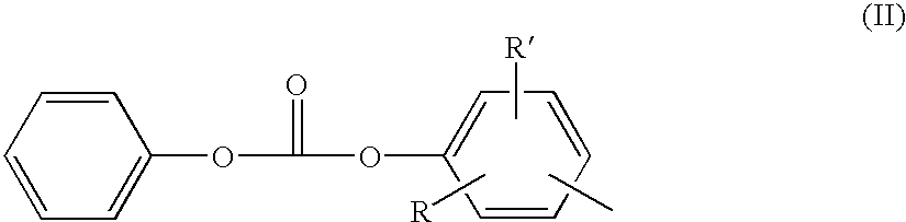
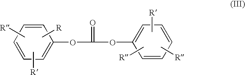
- Diaryl carbonates are those diaryl esters of formula (II):
- R, R′ and R′′ independently of one another, may be H, optionally branched C 1 to C 34 alkyl/cycloalkyl, C 7 to C 34 alkylaryl or C 6 to C 34 aryl, for example:
- the phenolic compounds used as carbonates may also be used directly as monohydroxyaryl compound in addition to one of the above-mentioned carbonates in order to influence the terminal groups of the oligocarbonate or the polycarbonate.
- a monohydroxyaryl compound of which the boiling point is higher than that of the monohydroxyaryl compound from which the diaryl carbonate has been formed should be selected.
- Preferred mixtures are those with diphenylcarbonate.
- the free monohydroxyaryl compound content may be 0.4 to 17 mol %, preferably 1.3 to 8.6 mol % (based on the dihydroxyaryl compound).
- the addition may be made both before the reaction and also completely or partially during the reaction.
- the diaryl carbonates are used in 1.02 to 1.3 mol, preferably 1.04 to 1.25 mol, particularly preferably 1.06 to 1.20 mol, based on 1 mol dihydroxyaryl compound. Mixtures of the above-mentioned diaryl carbonates may also be used.
- Ammonium or phosphonium catalysts which for the purpose of this application are also jointly designated onium compounds, are used for the synthesis. They are preferably used in quantities of 10 ⁇ 8 to 10 ⁇ 3 mol, based on 1 mol dihydroxyaryl compound, particularly preferably in quantities of 10 ⁇ 7 to 10 ⁇ 4 mol.
- Phosphonium salts optionally in combination with other suitable catalysts, such as other onium compounds, alkali or alkaline-earth metal compounds, may be used as catalyst for the production of the oligocarbonates.
- Phosphonium salts are those of formula (IV):
- R 1 ⁇ 4 which may be the same or different, represent C 1 to C 10 alkyls, C 6 to C 10 aryls, C 7 to C 10 arylalkyls or C 5 to C 6 cycloalkyls, preferably methyl or C 6 to C 14 aryls, particularly preferably methyl or phenyl and
- X ⁇ may be an anion such as hydroxide, sulphate, hydrogen sulphate, hydrogen carbonate, carbonate, a halide, preferably chloride, or an alkoxide of formula OR, wherein R may be C 6 to C 14 aryl or C 7 to C 12 aralkyl, preferably phenyl.
- Preferred catalysts are tetraphenylphosphoniumchloride, tetraphenylphosphoniumhydroxide, tetraphenylphosphoniumphenolate, particularly, preferably, tetraphenylphosphoniumphenolate.
- Preferred quantities of phosphonium salt catalysts are 10 ⁇ 8 to 10 ⁇ 3 mol per mol dihydroxyaryl compound and the most preferred quantities of catalyst are 10 ⁇ 7 to 10 ⁇ 4 mol per mol dihydroxyaryl compound.
- co-catalysts may optionally be used in addition to the phosphonium salt in order to increase the polymerisation rate.
- These include salts of alkali metals and alkaline-earth metals, such as hydroxides, alkoxides and aryloxides of lithium, sodium and potassium, preferably hydroxide, alkoxide or aryloxide salts of sodium. Most preferred are sodium hydroxide, disodium bisphenolate and preferably sodium phenolate.
- the quantities of co-catalyst may be in the range of 1 to 2,000 ppb (parts per billion), preferably 5 to 1,000 ppb and most preferably 10 to 500 ppb, calculated as sodium respectively. These may be introduced during production of the oligocarbonates or else first added prior to polycondensation. These catalysts are effective until the conclusion of polycondensation.
- the oligocarbonates may be deliberately branched and may therefore contain small quantities of 0.02 to 3.6 mol % (based on the dihydroxyaryl compound) of branching agents.
- Suitable branching agents include compounds suitable for polycarbonate production with three and more functional groups, preferably those with three or more than three phenolic OH groups, for example 1,1,1-tri-(4-hydroxyphenyl)ethane and isatinbiscresol.
- oligocarbonates in the context of the present invention refers to condensates with a relative viscosity between 1.03 and 1.20, preferably between 1.06 and 1.15, particularly preferably between 1.06 and 1.10.
- the relative viscosity is shown as the quotient of the viscosity of the solvent and the viscosity of the oligomer dissolved in this solvent. It has been determined in dichloromethane at a concentration of 5 g/l at 25° C.
- the oligocarbonates are the starting products for polycondensation to polycarbonates.
- Diaryl carbonates or dihydroxyaryl compounds may be added prior to condensation in order to correct the ratio of terminal phenolic OH groups to terminal aryl carbonate groups and deliberately achieve the desired and sought ratio of terminal groups or the concentration of terminal OH groups in the final polycarbonate.
- the terminal phenyl carbonate group may be partially altered by adding substituted monohydroxyaryl compounds, optionally also the diary carbonates thereof.
- the oligocarbonates may be conveyed directly from their production process to the polycondensation reactor.
- a further particular advantage is that the production of polycarbonates according to the invention does not have to be linked to the plant for producing the oligocarbonates.
- This allows polycarbonates to be produced at sites which do not have the typical infrastructure for constructing chemical plant.
- the solid oligocarbonate originating from a plant at a different site is melted in suitable units such as extruders and, optionally after addition of monomers to correct the ratio of terminal phenolic OH groups to terminal aryl carbonate groups and optionally catalysts to increase the reaction rate during polycondensation, is conveyed and condensed, for example in the polycondensation reactors according to the invention.
- the quantities of monohydroxyaryl compounds to be cleaved are small and do not pose any problems.
- diaryl carbonates and dihydroxyaryl compounds and production of the oligomer which are generally associated with high potential with respect to the environment, for example due to chlorine, carbon monoxide, phosgene, halogenated solvent, wastewater and large amounts of monohydroxyaryl compounds, may be carried out at different sites.
- auxiliaries and reinforcing agents may be added to the oligocarbonates prior to synthesis to high molecular polycarbonates.
- these include: heat and UV stabilisers, flow promoters, mould-release agents, flame retardants, pigments, finely dispersed minerals, fibrous material, for example alkyl and aryl phosphites, phosphates, phosphanes, low molecular carbonic acid esters, halogen compounds, salts, chalks, quartz powder, glass and carbon fibres, pigments and combinations thereof.
- Compounds of this type are described, for example, in WO 99/55772, pages 15 to 25 and in “Plastics Additives”, R. Gumbleter and H. Müller, Hanser Publishers 1983.
- the polycarbonates obtainable by the process according to the invention have relative viscosities of 1.18 to 1.40, preferably 1.18 to 1.36, particularly preferably 1.18 to 1.34.
- the relative viscosity is shown as the quotient of the viscosity of the solvent and the viscosity of the polymer dissolved in this solvent. They have been determined in dichloromethane at a concentration of 5 g/l at 25° C.
- Oligocarbonate melt produced from bisphenol A and diphenylcarbonate with tetraphenylphosphoniumphenolate catalyst, with a relative viscosity of 1,081, a terminal OH group content of 0.55% and a temperature of 270° C. are fed directly from their production process into a reactor, as described above, via a pressurising means.
- the reactor is heated to 270° C. and is under a vacuum of 7.3 mbar.
- the rotor speed is 2.5 rpm; the mean residence time 45 minutes.
- the product continuously removed from the reactor by a gear pump has a relative viscosity of 1.171 with a terminal OH group content of 0.13% and is conveyed via a heat exchanger heated with heat-carrying oil at 295° C. into a further reactor, as described above, but designed for higher melt viscosities.
- the vapour stream is partially condensed, the remainder being taken up in the vacuum station.
- the second reactor is adjusted to 295° C. and is under a vacuum of 1.3 mbar.
- the rotor speed is 0.8 rpm; the mean residence time is 130 minutes.
- the vapours are diverted into the vacuum station.
- the polycarbonate continuously removed by means of a gear pump has a relative viscosity of 1.287 and a terminal OH group content of 290 ppm.
- the YI value is determined on the polycarbonate. It is 1.42.
- YI was determined according to ASTM E 313 on injection moulded samples 4 mm thick. The injection temperature was 300° C.
Landscapes
- Chemical & Material Sciences (AREA)
- Organic Chemistry (AREA)
- Chemical Kinetics & Catalysis (AREA)
- Health & Medical Sciences (AREA)
- Medicinal Chemistry (AREA)
- Polymers & Plastics (AREA)
- Polyesters Or Polycarbonates (AREA)
Abstract
Description

Claims (8)
Applications Claiming Priority (3)
| Application Number | Priority Date | Filing Date | Title |
|---|---|---|---|
| DE10119851 | 2001-04-24 | ||
| DE10119851A DE10119851A1 (en) | 2001-04-24 | 2001-04-24 | Process for the continuous production of polycarbonates by the melt transesterification process |
| DE10119851.5 | 2001-04-24 |
Publications (2)
| Publication Number | Publication Date |
|---|---|
| US20020188091A1 US20020188091A1 (en) | 2002-12-12 |
| US6630563B2 true US6630563B2 (en) | 2003-10-07 |
Family
ID=7682403
Family Applications (1)
| Application Number | Title | Priority Date | Filing Date |
|---|---|---|---|
| US10/127,786 Expired - Lifetime US6630563B2 (en) | 2001-04-24 | 2002-04-22 | Process for continuous production of polycarbonates and a reactor therefor |
Country Status (10)
| Country | Link |
|---|---|
| US (1) | US6630563B2 (en) |
| EP (1) | EP1253163B1 (en) |
| JP (2) | JP2004523647A (en) |
| KR (1) | KR100856652B1 (en) |
| CN (1) | CN100335528C (en) |
| AT (1) | ATE339462T1 (en) |
| DE (2) | DE10119851A1 (en) |
| ES (1) | ES2272599T3 (en) |
| TW (1) | TWI302544B (en) |
| WO (1) | WO2002085967A1 (en) |
Cited By (11)
| Publication number | Priority date | Publication date | Assignee | Title |
|---|---|---|---|---|
| US20040225454A1 (en) * | 2003-04-08 | 2004-11-11 | Rainer Herrmann | Method and apparatus for determining the mass of portioned units of active substances |
| US20050131197A1 (en) * | 2003-12-06 | 2005-06-16 | Uwe Hucks | Transesterification process for the production of polycarbonates having a low content of volatile compounds |
| US20050197489A1 (en) * | 2003-12-06 | 2005-09-08 | Uwe Hucks | Process for stripping monomers and other volatile constituents from polymer melts |
| US20060056776A1 (en) * | 2003-07-30 | 2006-03-16 | Joseph Scheibenreif | Flexible substrate for routing fibers in an optical transceiver |
| US20080319156A1 (en) * | 2006-05-11 | 2008-12-25 | Bayer Materialscience Ag | Process For The Preparation Of Polycarbonate By The Melt Transesterification Process |
| US20090117314A1 (en) * | 2007-11-07 | 2009-05-07 | Bayer Materialscience Ag | Process for the preparation of polycarbonate by the melt transesterification method |
| US20110003945A1 (en) * | 2008-02-29 | 2011-01-06 | Bayer Materialscience Ag | Polycarbonates comprising cyclic oligomers and having an improved flow behavior |
| US20110040066A1 (en) * | 2008-04-18 | 2011-02-17 | Bayer Materialscience Ag | Polycarbonates having rearrangement structures, cyclic and linear oligomers and also flow behavior |
| EP2428266A1 (en) | 2010-09-10 | 2012-03-14 | Mega Data GmbH | Polymerization of high viscosity materials |
| EP2552995B1 (en) | 2010-04-01 | 2015-12-02 | Covestro Deutschland AG | Melt polycarbonate having improved heat ageing |
| US10189941B2 (en) | 2014-12-04 | 2019-01-29 | Covestro Deutschland Ag | Polycarbonate compositions containing polyethylene wax |
Families Citing this family (19)
| Publication number | Priority date | Publication date | Assignee | Title |
|---|---|---|---|---|
| DE10114804A1 (en) * | 2001-03-26 | 2002-10-10 | Bayer Ag | Process for the production of polycarbonates |
| DE10215498A1 (en) * | 2002-04-09 | 2003-10-23 | Bayer Ag | Storage of phosphonium phenolate catalysts and their use as transesterification catalysts |
| DE102006025943B4 (en) | 2006-06-02 | 2008-09-18 | Uhde Inventa-Fischer Gmbh | final reactor |
| DE102006025942B4 (en) | 2006-06-02 | 2011-07-07 | Uhde Inventa-Fischer GmbH & Co. KG, 13509 | Process for the continuous preparation of high molecular weight polyesters by esterification of dicarboxylic acids and / or transesterification of dicarboxylic acids with diols and / or mixtures thereof and device therefor |
| DE102012105296A1 (en) | 2012-06-19 | 2013-12-19 | Epc Engineering Consulting Gmbh | Process and plant for the production of polycarbonate |
| CN103623764B (en) * | 2013-12-06 | 2016-05-04 | 浙江长江搅拌设备有限公司 | Be applicable to the horizontal reactor of hyperviscosity fluid |
| TWI689527B (en) * | 2015-01-15 | 2020-04-01 | 荷蘭商蜆殼國際研究所 | Use of composition containing titanium or zirconium alkoxide or aromatic oxide in preparation method of aromatic carbonate |
| CN105504255B (en) * | 2016-01-11 | 2017-06-16 | 中蓝晨光化工研究设计院有限公司 | A kind of continuous fusion polymerization prepares the production technology of makrolon |
| EP3452530B1 (en) | 2016-05-04 | 2020-09-30 | Covestro Intellectual Property GmbH & Co. KG | Copolycarbonate as support material for 3d printing |
| EP3581605A1 (en) | 2018-06-14 | 2019-12-18 | Covestro Deutschland AG | Melting ester interchange method for simultaneously producing at least two different polycarbonates in a production plant |
| KR20220045150A (en) | 2019-08-08 | 2022-04-12 | 코베스트로 인텔렉쳐 프로퍼티 게엠베하 운트 콤파니 카게 | How to prepare polycarbonate |
| EP3838979B1 (en) | 2019-12-17 | 2024-06-26 | Covestro Deutschland AG | Melt polycarbonate with improved optical properties |
| WO2022065331A1 (en) * | 2020-09-23 | 2022-03-31 | 三菱瓦斯化学株式会社 | Production method for polysiloxane, composition including polysiloxane, and molded body |
| CN117500859A (en) | 2021-06-15 | 2024-02-02 | 科思创德国股份有限公司 | Oligomeric esters containing resorcinol and isophthalic acid and/or terephthalic acid, corresponding polyester carbonates and their preparation |
| KR20240021176A (en) | 2021-06-15 | 2024-02-16 | 코베스트로 도이칠란트 아게 | Oligoesters comprising resorcinol and iso- and/or terephthalic acid, corresponding polyester carbonates and their preparation |
| EP4377376A1 (en) | 2021-07-27 | 2024-06-05 | Covestro Deutschland AG | Method for preparing a polysiloxane-polycarbonate block copolymer using at least one special condensation reactor |
| EP4124632A1 (en) | 2021-07-27 | 2023-02-01 | Covestro Deutschland AG | Method for producing a polysiloxane-polycarbonate block copolymer |
| CN119213054A (en) | 2022-04-27 | 2024-12-27 | 科思创德国股份有限公司 | Polycarbonate cocondensates having phenolic structural units |
| WO2025109040A1 (en) | 2023-11-22 | 2025-05-30 | Sabic Global Technologies B.V. | Process for producing polycarbonate |
Citations (20)
| Publication number | Priority date | Publication date | Assignee | Title |
|---|---|---|---|---|
| DE1031512B (en) | 1955-12-21 | 1958-06-04 | Bayer Ag | Process for the production of high molecular weight fiber and film forming polycarbonates |
| US3022272A (en) | 1962-02-20 | Process for the production of high | ||
| GB1007302A (en) | 1963-07-24 | 1965-10-13 | Bayer Ag | Improvements in and relating to the production of thermoplastic polycondensation products |
| US3684458A (en) | 1970-01-08 | 1972-08-15 | Firestone Tire & Rubber Co | Propulsion and processing apparatus for flowable materials |
| GB1435767A (en) | 1972-09-12 | 1976-05-12 | Basf Ag | Apparatus for the manufacture of high molecular weight polyalkylene terephthalates |
| US5055536A (en) | 1990-08-09 | 1991-10-08 | Shell Oil Company | Process to prepare vinyl ether polymers |
| US5334358A (en) | 1990-06-06 | 1994-08-02 | Bayer Aktiengesellschaft | Self-cleaning reactor/mixer with large useful volume |
| US5340905A (en) | 1992-11-12 | 1994-08-23 | Bayer Aktiengesellschaft | Process for the preparation of thermoplastic polycarbonates |
| US5399012A (en) | 1991-08-09 | 1995-03-21 | Bayer Aktiengesellschaft | Fully self-cleaning reactor/mixer with a large usable volume |
| US5399659A (en) | 1993-04-16 | 1995-03-21 | Bayer Aktiengesellschaft | Two-stage process for the production of thermoplastic polycarbonate |
| US5498688A (en) | 1993-04-16 | 1996-03-12 | Daicel Chemical Industries, Ltd. | Two-step process for the preparation of a (co)polycarbonate by transesterification |
| US5599507A (en) | 1994-11-09 | 1997-02-04 | Shaw; Gordon | Reactor apparatus for preparing a polymeric material |
| US5767224A (en) | 1996-03-27 | 1998-06-16 | Bayer Aktiengesellschaft | Two-step process for the production of thermoplastic polycarbonate |
| US5779986A (en) | 1994-12-30 | 1998-07-14 | Karl Fischer Industrieanlagen Gmbh | Reactor device for free-flowing and higher-viscosity media |
| US5816697A (en) | 1995-12-05 | 1998-10-06 | Teijin Limited | Viscous liquid stirring device and a process for producing polycarbonate by using the stirring device |
| US5912318A (en) | 1997-04-03 | 1999-06-15 | Asahi Kasei Kogyo Kabushiki Kaisha | Method for producing an aromatic polycarbonate |
| US5912289A (en) | 1996-01-25 | 1999-06-15 | Asahi Kasei Kogyo Kabushiki Kaisha | Aromatic polycarbonate composition having improved thermal stability, and method for producing the same |
| US5932683A (en) | 1996-03-05 | 1999-08-03 | Asahi Kasei Kogyo Kabushiki Kaisha | Polycarbonate comprising different kinds of bonding units and process for the preparation thereof |
| US6265525B1 (en) | 1997-11-28 | 2001-07-24 | Hitachi, Ltd. | Method and device for manufacturing polycarbonate |
| US6339138B1 (en) | 1998-11-04 | 2002-01-15 | General Electric Company | Method of manufacturing polycarbonates |
Family Cites Families (1)
| Publication number | Priority date | Publication date | Assignee | Title |
|---|---|---|---|---|
| DE4447422C2 (en) * | 1994-12-30 | 1996-10-31 | Fischer Karl Ind Gmbh | Reactor device for flowable media |
-
2001
- 2001-04-24 DE DE10119851A patent/DE10119851A1/en not_active Withdrawn
-
2002
- 2002-04-17 EP EP02008197A patent/EP1253163B1/en not_active Expired - Lifetime
- 2002-04-17 DE DE50208103T patent/DE50208103D1/en not_active Expired - Lifetime
- 2002-04-17 ES ES02008197T patent/ES2272599T3/en not_active Expired - Lifetime
- 2002-04-17 AT AT02008197T patent/ATE339462T1/en not_active IP Right Cessation
- 2002-04-22 US US10/127,786 patent/US6630563B2/en not_active Expired - Lifetime
- 2002-04-23 KR KR1020037013780A patent/KR100856652B1/en not_active Expired - Fee Related
- 2002-04-23 WO PCT/EP2002/004442 patent/WO2002085967A1/en not_active Ceased
- 2002-04-23 JP JP2002583493A patent/JP2004523647A/en active Pending
- 2002-04-23 CN CNB028087941A patent/CN100335528C/en not_active Expired - Fee Related
- 2002-04-24 TW TW091108399A patent/TWI302544B/en not_active IP Right Cessation
-
2012
- 2012-03-13 JP JP2012056031A patent/JP2012140632A/en active Pending
Patent Citations (20)
| Publication number | Priority date | Publication date | Assignee | Title |
|---|---|---|---|---|
| US3022272A (en) | 1962-02-20 | Process for the production of high | ||
| DE1031512B (en) | 1955-12-21 | 1958-06-04 | Bayer Ag | Process for the production of high molecular weight fiber and film forming polycarbonates |
| GB1007302A (en) | 1963-07-24 | 1965-10-13 | Bayer Ag | Improvements in and relating to the production of thermoplastic polycondensation products |
| US3684458A (en) | 1970-01-08 | 1972-08-15 | Firestone Tire & Rubber Co | Propulsion and processing apparatus for flowable materials |
| GB1435767A (en) | 1972-09-12 | 1976-05-12 | Basf Ag | Apparatus for the manufacture of high molecular weight polyalkylene terephthalates |
| US5334358A (en) | 1990-06-06 | 1994-08-02 | Bayer Aktiengesellschaft | Self-cleaning reactor/mixer with large useful volume |
| US5055536A (en) | 1990-08-09 | 1991-10-08 | Shell Oil Company | Process to prepare vinyl ether polymers |
| US5399012A (en) | 1991-08-09 | 1995-03-21 | Bayer Aktiengesellschaft | Fully self-cleaning reactor/mixer with a large usable volume |
| US5340905A (en) | 1992-11-12 | 1994-08-23 | Bayer Aktiengesellschaft | Process for the preparation of thermoplastic polycarbonates |
| US5498688A (en) | 1993-04-16 | 1996-03-12 | Daicel Chemical Industries, Ltd. | Two-step process for the preparation of a (co)polycarbonate by transesterification |
| US5399659A (en) | 1993-04-16 | 1995-03-21 | Bayer Aktiengesellschaft | Two-stage process for the production of thermoplastic polycarbonate |
| US5599507A (en) | 1994-11-09 | 1997-02-04 | Shaw; Gordon | Reactor apparatus for preparing a polymeric material |
| US5779986A (en) | 1994-12-30 | 1998-07-14 | Karl Fischer Industrieanlagen Gmbh | Reactor device for free-flowing and higher-viscosity media |
| US5816697A (en) | 1995-12-05 | 1998-10-06 | Teijin Limited | Viscous liquid stirring device and a process for producing polycarbonate by using the stirring device |
| US5912289A (en) | 1996-01-25 | 1999-06-15 | Asahi Kasei Kogyo Kabushiki Kaisha | Aromatic polycarbonate composition having improved thermal stability, and method for producing the same |
| US5932683A (en) | 1996-03-05 | 1999-08-03 | Asahi Kasei Kogyo Kabushiki Kaisha | Polycarbonate comprising different kinds of bonding units and process for the preparation thereof |
| US5767224A (en) | 1996-03-27 | 1998-06-16 | Bayer Aktiengesellschaft | Two-step process for the production of thermoplastic polycarbonate |
| US5912318A (en) | 1997-04-03 | 1999-06-15 | Asahi Kasei Kogyo Kabushiki Kaisha | Method for producing an aromatic polycarbonate |
| US6265525B1 (en) | 1997-11-28 | 2001-07-24 | Hitachi, Ltd. | Method and device for manufacturing polycarbonate |
| US6339138B1 (en) | 1998-11-04 | 2002-01-15 | General Electric Company | Method of manufacturing polycarbonates |
Non-Patent Citations (1)
| Title |
|---|
| Chemistry and Physics of Polycarbonates, by Hermann Schnell, Polymers Reviews, vol. 9, (month unavailable) 1964, pp. 44-51. |
Cited By (18)
| Publication number | Priority date | Publication date | Assignee | Title |
|---|---|---|---|---|
| US7337074B2 (en) * | 2003-04-08 | 2008-02-26 | Tews Elektronik | Method and apparatus for determining the mass of portioned units of active substances |
| US20040225454A1 (en) * | 2003-04-08 | 2004-11-11 | Rainer Herrmann | Method and apparatus for determining the mass of portioned units of active substances |
| US20060056776A1 (en) * | 2003-07-30 | 2006-03-16 | Joseph Scheibenreif | Flexible substrate for routing fibers in an optical transceiver |
| US20050131197A1 (en) * | 2003-12-06 | 2005-06-16 | Uwe Hucks | Transesterification process for the production of polycarbonates having a low content of volatile compounds |
| US20050197489A1 (en) * | 2003-12-06 | 2005-09-08 | Uwe Hucks | Process for stripping monomers and other volatile constituents from polymer melts |
| US7060788B2 (en) | 2003-12-06 | 2006-06-13 | Bayer Materialscience Ag | Process for stripping monomers and other volatile constituents from polymer melts |
| US7279544B2 (en) | 2003-12-06 | 2007-10-09 | Bayer Materialscience Ag | Transesterification process for the production of polycarbonates having a low content of volatile compounds |
| US20080319156A1 (en) * | 2006-05-11 | 2008-12-25 | Bayer Materialscience Ag | Process For The Preparation Of Polycarbonate By The Melt Transesterification Process |
| US7814626B2 (en) | 2007-05-11 | 2010-10-19 | Bayer Materialscience Ag | Process for the preparation of polycarbonate by the melt transesterification process |
| US20090117314A1 (en) * | 2007-11-07 | 2009-05-07 | Bayer Materialscience Ag | Process for the preparation of polycarbonate by the melt transesterification method |
| US20110003945A1 (en) * | 2008-02-29 | 2011-01-06 | Bayer Materialscience Ag | Polycarbonates comprising cyclic oligomers and having an improved flow behavior |
| US8110649B2 (en) | 2008-02-29 | 2012-02-07 | Bayer Materialscience Ag | Polycarbonates comprising cyclic oligomers and having an improved flow behavior |
| US20110040066A1 (en) * | 2008-04-18 | 2011-02-17 | Bayer Materialscience Ag | Polycarbonates having rearrangement structures, cyclic and linear oligomers and also flow behavior |
| US8158745B2 (en) | 2008-04-18 | 2012-04-17 | Bayer Materialscience Ag | Polycarbonates having rearrangement structures, cyclic and linear oligomers and also flow behavior |
| EP2552995B1 (en) | 2010-04-01 | 2015-12-02 | Covestro Deutschland AG | Melt polycarbonate having improved heat ageing |
| EP2428266A1 (en) | 2010-09-10 | 2012-03-14 | Mega Data GmbH | Polymerization of high viscosity materials |
| US8796401B2 (en) | 2010-09-10 | 2014-08-05 | Princo Middle East Fze | Polymerization of high viscosity materials |
| US10189941B2 (en) | 2014-12-04 | 2019-01-29 | Covestro Deutschland Ag | Polycarbonate compositions containing polyethylene wax |
Also Published As
| Publication number | Publication date |
|---|---|
| US20020188091A1 (en) | 2002-12-12 |
| DE50208103D1 (en) | 2006-10-26 |
| KR20040012767A (en) | 2004-02-11 |
| TWI302544B (en) | 2008-11-01 |
| WO2002085967A1 (en) | 2002-10-31 |
| ES2272599T3 (en) | 2007-05-01 |
| JP2004523647A (en) | 2004-08-05 |
| KR100856652B1 (en) | 2008-09-04 |
| DE10119851A1 (en) | 2002-10-31 |
| JP2012140632A (en) | 2012-07-26 |
| EP1253163A1 (en) | 2002-10-30 |
| ATE339462T1 (en) | 2006-10-15 |
| CN100335528C (en) | 2007-09-05 |
| EP1253163B1 (en) | 2006-09-13 |
| CN1505649A (en) | 2004-06-16 |
Similar Documents
| Publication | Publication Date | Title |
|---|---|---|
| US6630563B2 (en) | Process for continuous production of polycarbonates and a reactor therefor | |
| JP4275317B2 (en) | Method and polymerizer for producing aromatic polycarbonate | |
| US5596067A (en) | Free fall polymerization process for the production of polycarbonates | |
| KR100420017B1 (en) | Process for producing aromatic polycarbonate | |
| JP4181601B2 (en) | Method for efficiently producing aromatic polycarbonate | |
| US6835797B2 (en) | Process for producing oligocarbonates | |
| JP3966553B2 (en) | System for producing aromatic polycarbonate | |
| JP4152419B2 (en) | Polymerization apparatus for producing aromatic polycarbonate | |
| JP3522028B2 (en) | Method for producing aromatic polycarbonate having guide | |
| JPH08325373A (en) | Production of aromatic polycarbonate using guide | |
| JP3200345B2 (en) | Method for producing aromatic polycarbonate with guide | |
| JPH10324742A (en) | Production of aromatic polycarbonate | |
| JP3522027B2 (en) | Method for producing aromatic polycarbonate | |
| JPH0632887A (en) | Production of aromatic polycarbonate | |
| JPH0665365A (en) | Production of aromatic polycarbonate | |
| JP3414566B2 (en) | Manufacturing method of aromatic polycarbonate | |
| JP3522029B2 (en) | Manufacturing method of aromatic polycarbonate | |
| JP2022154646A (en) | Method and device for producing polycarbonate | |
| JPH10251396A (en) | Production of aromatic polycarbonate | |
| JPH08231704A (en) | Production of polycarbonate resin by using guide | |
| JPH08231703A (en) | Production of polycarbonate resin |
Legal Events
| Date | Code | Title | Description |
|---|---|---|---|
| AS | Assignment |
Owner name: BAYER AKTIENGESELLSCHAFT, GERMANY Free format text: ASSIGNMENT OF ASSIGNORS INTEREST;ASSIGNORS:HUCKS, UWE;KOENIG, THOMAS;KRATSCHMER, SILKE;AND OTHERS;REEL/FRAME:013850/0455;SIGNING DATES FROM 20020529 TO 20020624 |
|
| STCF | Information on status: patent grant |
Free format text: PATENTED CASE |
|
| FPAY | Fee payment |
Year of fee payment: 4 |
|
| FEPP | Fee payment procedure |
Free format text: PAYOR NUMBER ASSIGNED (ORIGINAL EVENT CODE: ASPN); ENTITY STATUS OF PATENT OWNER: LARGE ENTITY |
|
| FEPP | Fee payment procedure |
Free format text: PAYOR NUMBER ASSIGNED (ORIGINAL EVENT CODE: ASPN); ENTITY STATUS OF PATENT OWNER: LARGE ENTITY |
|
| FPAY | Fee payment |
Year of fee payment: 8 |
|
| FPAY | Fee payment |
Year of fee payment: 12 |
|
| AS | Assignment |
Owner name: BAYER MATERIALSCIENCE AG, GERMANY Free format text: ASSIGNMENT OF ASSIGNORS INTEREST;ASSIGNOR:BAYER AG;REEL/FRAME:038044/0799 Effective date: 20160229 |
|
| AS | Assignment |
Owner name: COVESTRO DEUTSCHLAND AG, GERMANY Free format text: CHANGE OF NAME;ASSIGNOR:BAYER MATERIALSCIENCE AG;REEL/FRAME:038399/0358 Effective date: 20150901 |
|
| AS | Assignment |
Owner name: COVESTRO DEUTSCHLAND AG, GERMANY Free format text: CHANGE OF NAME;ASSIGNOR:BAYER MATERIALSCIENCE AG;REEL/FRAME:038363/0921 Effective date: 20150901 |