US6629787B2 - Apparatus and method for adjusting a head gap of an inkjet printer - Google Patents
Apparatus and method for adjusting a head gap of an inkjet printer Download PDFInfo
- Publication number
- US6629787B2 US6629787B2 US09/899,292 US89929201A US6629787B2 US 6629787 B2 US6629787 B2 US 6629787B2 US 89929201 A US89929201 A US 89929201A US 6629787 B2 US6629787 B2 US 6629787B2
- Authority
- US
- United States
- Prior art keywords
- head
- head gap
- eccentric shaft
- printing medium
- gap
- Prior art date
- Legal status (The legal status is an assumption and is not a legal conclusion. Google has not performed a legal analysis and makes no representation as to the accuracy of the status listed.)
- Expired - Fee Related
Links
Images


Classifications
-
- B—PERFORMING OPERATIONS; TRANSPORTING
- B41—PRINTING; LINING MACHINES; TYPEWRITERS; STAMPS
- B41J—TYPEWRITERS; SELECTIVE PRINTING MECHANISMS, i.e. MECHANISMS PRINTING OTHERWISE THAN FROM A FORME; CORRECTION OF TYPOGRAPHICAL ERRORS
- B41J2/00—Typewriters or selective printing mechanisms characterised by the printing or marking process for which they are designed
- B41J2/22—Typewriters or selective printing mechanisms characterised by the printing or marking process for which they are designed characterised by selective application of impact or pressure on a printing material or impression-transfer material
- B41J2/23—Typewriters or selective printing mechanisms characterised by the printing or marking process for which they are designed characterised by selective application of impact or pressure on a printing material or impression-transfer material using print wires
- B41J2/235—Print head assemblies
-
- B—PERFORMING OPERATIONS; TRANSPORTING
- B41—PRINTING; LINING MACHINES; TYPEWRITERS; STAMPS
- B41J—TYPEWRITERS; SELECTIVE PRINTING MECHANISMS, i.e. MECHANISMS PRINTING OTHERWISE THAN FROM A FORME; CORRECTION OF TYPOGRAPHICAL ERRORS
- B41J25/00—Actions or mechanisms not otherwise provided for
- B41J25/304—Bodily-movable mechanisms for print heads or carriages movable towards or from paper surface
- B41J25/308—Bodily-movable mechanisms for print heads or carriages movable towards or from paper surface with print gap adjustment mechanisms
- B41J25/3082—Bodily-movable mechanisms for print heads or carriages movable towards or from paper surface with print gap adjustment mechanisms with print gap adjustment means on the print head carriage, e.g. for rotation around a guide bar or using a rotatable eccentric bearing
-
- B—PERFORMING OPERATIONS; TRANSPORTING
- B41—PRINTING; LINING MACHINES; TYPEWRITERS; STAMPS
- B41J—TYPEWRITERS; SELECTIVE PRINTING MECHANISMS, i.e. MECHANISMS PRINTING OTHERWISE THAN FROM A FORME; CORRECTION OF TYPOGRAPHICAL ERRORS
- B41J25/00—Actions or mechanisms not otherwise provided for
- B41J25/304—Bodily-movable mechanisms for print heads or carriages movable towards or from paper surface
- B41J25/308—Bodily-movable mechanisms for print heads or carriages movable towards or from paper surface with print gap adjustment mechanisms
Definitions
- the present invention relates to an apparatus for adjusting a head gap of an ink jet printer, and, more particularly, to an apparatus for adjusting the head gap of the ink jet printer capable of automatically adjusting the head gap.
- an ink jet printer includes an eccentric shaft disposed in a main frame, a print head conveying bracket that is moved along the eccentric shaft, an ink cartridge disposed on the conveying bracket and having a print head, a conveying means for reciprocating the conveying bracket in a lengthwise direction of the eccentric shaft, and a head gap adjusting device for adjusting a head gap defined between the print head and a printing medium.
- the conveying means includes a conveying belt disposed on the main frame for circulating in the lengthwise direction of the eccentric shaft, and includes a motor for circulating the conveying belt.
- the conveying belt is connected to the conveying bracket. Accordingly, the conveying bracket is moved together with the conveying belt that is circulated by the driving force of the motor.
- the head gap adjusting device adjusts the head gap according to the thickness of the printing medium being supplied to the ink jet printer.
- the head gap adjusting device includes a bushing member rotatably disposed on the main frame, and a lever for turning the bushing member.
- the eccentric shaft is turned together with the bushing member. Accordingly, the height of the eccentric shaft is varied according to the position of the lever and, thus, the head gap is adjusted. For example, when the printing medium being supplied is a relatively thick material, such as an envelope, a user adjusts the head gap by turning the lever in a direction which will raise the eccentric shaft. When the printing medium being supplied is a relatively thinner material, such as an A4 sheet, the user adjusts the head gap by turning the lever in a direction which will lower the eccentric shaft.
- the head gap typically cannot be variably adjusted. That is, the head gap adjusting device or apparatus is typically constructed to accommodate a limited type of printing medium, such as A4 sheet and envelope, or the like. Accordingly, the conventional head gap adjusting device apparatus typically cannot adjust the head gap efficiently according to printing mediums of different thickness.
- the present invention has been made to overcome the above-mentioned problem of the related art, and accordingly, it is an object, among other objects, of the present invention to provide an apparatus for adjusting a head gap of an inkjet printer having an improved structure for automatically adjusting the head gap according to various types of the printing medium being supplied to the ink jet printer.
- an apparatus for adjusting a head gap of an inkjet printer including: a main frame; an eccentric shaft including an eccentric supporting shaft at each end of the eccentric shaft, the eccentric shaft being rotatably disposed on the main frame by each eccentric supporting shaft; a head assembly movably disposed on the eccentric shaft, the head assembly including a print head for supplying an ink onto a printing medium for printing; a head gap detecting sensor for detecting the head gap defined between the printing medium and the print head; an eccentric shaft turning means for automatically adjusting the head gap by turning the eccentric shaft to move the eccentric shaft through a predetermined angle to move the head assembly to provide a predetermined head gap; and a controller for controlling the driving of the eccentric shaft turning means so as to move the eccentric shaft through the predetermined angle to compensate for the head gap detected by the head gap detecting sensor to provide the predetermined head gap.
- the eccentric shaft turning means includes: a gear disposed on the eccentric supporting shaft; and a motor connected to the gear, the motor being driven under the control of the controller for rotating the gear in a predetermined direction by a predetermined angle.
- an apparatus for adjusting a head gap of an inkjet printer including: a main frame; a head assembly including a print head; an eccentric shaft for movably supporting the head assembly, the eccentric shaft including a supporting shaft at each end of the eccentric shaft, each supporting shaft being rotatably supported on the main frame; a turning means for adjusting the head gap between the print head and the printing medium by selectively turning the eccentric shaft forward in a first direction and backward in a second direction opposite to the first direction by a predetermined angle.
- the turning means includes a pivot lever or pivot member formed or displayed on the supporting shaft for pivotal movement together with a rotatable movement of the supporting shaft; a movable member movably disposed on or with respect to the main frame for reciprocating movement on or with respect to the main frame, the movable member for providing the pivotal movement or the pivot lever by a reciprocating movement of the movable member; a driving portion or driving means for providing the reciprocating movement of the movable member; and a controller for controlling the driving of the driving means or driving portion.
- the movable member and the pivot lever each include a slant surface of a predetermined sloping degree, respectively, with the slant surface of the movable member being disposed in facing, opposing relation to the slant surface of the pivot member, and with the slant surface of the movable member and the slant surface of the pivot member each respectively moving in opposite directions during pivotal movement of the pivot member.
- the slant surface of the movable member and the slant surface of the pivot member each includes a projection formed on the respective slant surface, for limiting a range of movement of the movable member and the pivot member and for preventing the movable member from being separated from contact with the pivot member.
- the driving portion or driving means includes: a rack gear formed on a side of the movable member; a pinion gear rotatably formed on the main frame and for meshed engagement with the rack gear; and a motor for driving the pinion gear to provide the reciprocating movement of the movable member.
- the eccentric shaft includes: a shaft body on which the head assembly is movably disposed; and bushing members on which both ends of the shaft body are eccentrically supported, with the bushing members being rotatably disposed on the main frame, the pivot lever or pivot member being incorporated with at least one bushing member.
- a head gap detecting sensor disposed on the head assembly for detecting data corresponding to the head gap between a printing medium and the print head, and providing the detected data to the controller so that the controller can control the driving of the driving portion or driving means based on the detected data.
- a spring or spring member for elastically biasing the pivot lever or pivot member so as to a contact or position the pivot member in an engaging relation with the movable member.
- FIG. 1 is a schematic view illustrating a conventional head gap adjusting apparatus of an inkjet printer
- FIGS. 2A and 2B are views for explaining and illustrating the operation of a bushing member of FIG. 1, respectively;
- FIG. 3 is a schematic perspective view illustrating a head gap adjusting apparatus of an inkjet printer according to one preferred embodiment of the present invention
- FIG. 4 is a front view illustrating the head gap adjusting apparatus of FIG. 3;
- FIG. 5 is a front view illustrating a head assembly of FIG. 4 of the head gap adjusting apparatus of FIG. 3 being in a raised position;
- FIG. 6 is a schematic perspective view illustrating the head gap adjusting apparatus of an inkjet printer according to another preferred embodiment of the present invention.
- FIG. 7 is a schematic front view illustrating the head gap adjusting apparatus of FIG. 6;
- FIG. 8 is a schematic side view for illustrating and explaining the operation of the head gap adjusting apparatus of FIGS. 6 and 7;
- FIG. 9 is another schematic side view for illustrating and explaining the operation of the head gap adjusting apparatus of FIGS. 6 and 7 .
- FIGS. 1 through 9 This invention will be described in further detail by way of example with reference to the attached drawings of FIGS. 1 through 9, particularly FIGS. 3 through 9.
- an ink jet printer includes an eccentric shaft 2 disposed in a main frame 1 , a head conveying bracket 3 moved along the eccentric shaft 2 , an ink cartridge 4 disposed on the conveying bracket 3 and having a print head 4 a , a conveying means for reciprocating the conveying bracket 3 in a lengthwise direction of the eccentric shaft 2 , and a head gap adjusting device 7 , 8 for adjusting a head gap G indicating the arrows g 1 and g 2 defined between the print head 4 a and a printing medium P.
- the conveying means includes a conveying belt 5 disposed on the main frame 1 for circulating in the lengthwise direction of the eccentric shaft 2 , and a motor 6 for circulating the conveying belt 5 .
- the conveying belt 5 is connected to the conveying bracket 3 . Accordingly, the conveying bracket 3 is moved together with the conveying belt 5 that is circulated by the driving force of the motor 6 .
- the head gap adjusting device 7 , 8 adjusts the head gap G according to the thickness of the printing medium P being supplied to the ink jet printer.
- the head gap adjusting device 7 , 8 includes a bushing member 7 rotatably disposed on the main frame 1 , and a lever 8 for turning the bushing member 7 .
- the eccentric shaft 2 is turned together with the bushing member 7 . Accordingly, as shown in FIGS. 2A and 2B, the height of the eccentric shaft 2 is varied according to the position of the lever 8 and, thus, the head gap G is adjusted.
- the printing medium P being supplied is a relatively thick material, such as an envelope
- a user adjusts the head gap G by turning the lever 8 in a direction indicated by the arrow A, in FIG. 2A, which will raise the eccentric shaft 2 to a state shown in FIG. 2 B.
- the printing medium P being supplied is a relatively thinner material, such as an A4 sheet of paper
- the user adjusts the head gap G by turning the lever 8 in a direction indicated by the arrow B in FIG. 2B, which will lower the eccentric shaft 2 to a state such as shown in FIG. 2 A.
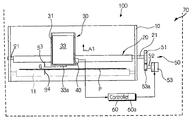
- the head gap adjusting apparatus 100 includes a main frame 10 , an eccentric shaft 20 rotatably disposed in the main frame 10 , a head assembly 30 movably supported on the eccentric shaft 20 , a head gap detecting sensor 40 formed on the head assembly 30 for being moved together with the head assembly 30 , a turning means 50 for turning the eccentric shaft 20 , and a controller 60 .
- the eccentric shaft 20 includes a pair of supporting shafts 21 each being respectively formed on both ends of the eccentric shaft 20 .
- the supporting shafts 21 are rotatably supported in the main frame 10 .
- the head assembly 30 includes a conveying bracket 31 and an ink cartridge 33 .
- the conveying bracket 31 is movably disposed on the eccentric shaft 20 .
- the conveying bracket 31 is reciprocated in a lengthwise direction of the eccentric shaft 20 by a conveying means that includes a conveying belt 13 .
- the conveying belt 13 supporting the conveying bracket 31 , is moved by a carrier motor 32 .
- the ink cartridge 33 is removably mounted on the conveying bracket 31 .
- a print head 33 a is formed to supply ink to the printing medium P that is fed by a feeding roller 11 .
- a head gap G is defined between the print head 33 a and the printing medium P.
- the head gap detecting sensor 40 is moved together with the conveying bracket 31 , although the head gap detecting sensor 40 can be otherwise appropriately located in the ink jet printer.
- the head gap detecting sensor 40 measures a distance, that is the head gap G between the printing medium P and the print head 33 a , and sends measurement data relating to the measured distance corresponding to the head gap G to the controller 60 , controller 60 being a central processing unit or a microprocessor, for example.
- controller 60 being a central processing unit or a microprocessor, for example.
- the head gap detecting sensor 40 can be a light receiving and emitting sensor, for example, for measuring the head gap G.
- the turning means 50 of the head gap adjusting apparatus 100 includes a gear 51 formed on one end of the supporting shaft 21 , and a motor 53 for driving the gear 51 .
- a shaft gear 53 a formed on a shaft 52 of the motor 53 is engaged with the gear 51 .
- the motor 53 can be mounted on or in communication with the main frame 10 , or on or in communication with a body 70 of the ink jet printer.
- the controller 60 controls the driving direction and the driving occurrence of the motor 53 .
- the operation of the head gap adjusting apparatus 100 of the inkjet printer of FIGS. 3 through 5 constructed as above according to a preferred embodiment of the present invention will now be described.
- the printing medium P is fed to a lower side of the print head 33 a by the feeding roller 11 .
- the head gap detecting sensor 40 emits light to the printing medium P, receives reflected light from the printing medium P and detects the length or distance of the head gap G.
- the detected data corresponding to the head gap G is sent to the controller 60 .
- the controller 60 compares the received detected data with a predetermined reference value corresponding to a head gap G for optimum printing on the printing medium P, the predetermined reference value being stored in a memory 60 a of controller 60 or provided to controller 60 , such as through an input key or selector of the ink jet printer or from a computer. For example, when the printing medium P is thicker, such as thicker than an A4 sheet, the detected data about the length or distance of the head gap G is determined to be lower than the predetermined reference value, thereby requiring an increase of the head gap G.
- the controller 60 sends a signal to the motor 53 causing the motor 53 to rotate in a corresponding predetermined direction a corresponding predetermined number of times, so as to move the head assembly 30 in the direction indicated by the arrow A 1 of FIG. 4 .
- the rotation of the motor 53 in the predetermined direction causes the gear 51 to be driven together with the shaft gear 53 a , turning the supporting shaft 21 through a corresponding predetermined angle corresponding to the head gap G for optimum printing on the printing medium P.
- the supporting shaft 21 is eccentrically formed with respect to the eccentric shaft 20 , the head assembly 30 supported on the eccentric shaft 20 is raised as shown in FIG.
- the head gap G between the print head 33 a and the printing medium P is adjusted appropriately for optimum printing on the printing medium P.
- the print head 33 a typically is lowered to adjust the head gap G. Accordingly, the detected data relating to a distance of the head gap G from the head gap detecting sensor 40 is compared by the controller 60 to a predetermined reference value corresponding to a head gap G for optimum printing on the printing medium P.
- the controller 60 controls the driving of the motor 53 causing the motor 53 to rotate in a corresponding predetermined direction a corresponding predetermined number of times, the corresponding predetermined direction to lower the head assembly 30 being opposite to the corresponding predetermined direction to raise the head assembly 30 .
- the gear 51 is thus oppositely turned by the motor 53 , the gear 51 being driven with gear shaft 53 , turning the supporting shaft 21 through a corresponding predetermined angle in an opposite direction to a direction for raising the head assembly 30 . Accordingly, the head assembly 30 supported on the eccentric shaft 20 is lowered by a predetermined distance in the direction of the arrow B 1 in FIG.
- the head gap G between the print head 33 a and the printing medium P is adjusted appropriately according to the thickness of the printing medium P.
- the controller 60 automatically adjusts the head gap G as previously described. That is, regardless of the type of the printing medium P, the controller 60 can maintain a desired length or distance of the head gap G.
- the controller 60 compares the data corresponding to the head gap G detected by head gap detecting sensor 40 to a predetermined reference value corresponding to a head gap G for optimum printing on the printing medium P, and the detected data corresponds to such predetermined reference value, no adjustment or no further adjustment of the head gap G is made by the controller 60 .
- the detected data corresponding to the head gap G indicates that the distance of the head gap G detected already corresponds to a head gap G for optimum printing on the printing medium P.
- the compatibility of the ink jet printer is increased since the ink jet printer can use various types of printing mediums P. Further, deterioration of the print quality when using different types of the printing medium P advantageously can be reduced or prevented.
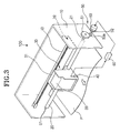
- the head gap adjusting apparatus 200 includes a main frame 110 , an eccentric shaft 120 rotatably disposed on the main frame 110 , a head assembly 130 movably disposed on the eccentric shaft 120 , and a shaft turning means 140 for turning the eccentric shaft 120 by a predetermined angle, and returning the eccentric shaft 120 to an original position.
- a feeding roller 111 is disposed in the main frame 110 to feed the printing medium P, which is picked up by a pickup means for the ink jet printer, to a lower side of the head assembly 130 .
- the feeding roller 111 is contact-rotated by a backup roller 113 .
- the eccentric shaft 120 of the head gap adjusting apparatus 200 includes a supporting shaft 121 rotatably disposed on the main frame 110 .
- a bushing member is an example of the supporting shaft 121 .
- the eccentric shaft 120 has a shaft body 123 that is eccentrically disposed with respect to the pivotal center of the bushing member 121 .
- a pair of supporting shafts 121 (hereafter referred to as bushing members 121 ) are respectively located at opposing ends of the eccentric shaft 120 on the shaft body 123 .
- the shaft body 123 is moved upward and downward according to the pivotal angle of each bushing member 121 , during the pivotal movement of each bushing member 121 .
- the head assembly 130 of the head gap adjusting apparatus 200 of FIGS. 6 through 9, is movably disposed on the shaft body 123 .
- the head assembly 130 is moved in a lengthwise direction of the shaft body 123 by a conveying means that includes a conveying belt, such as the motor 32 and the conveying belt 13 of the head gap adjusting apparatus 100 illustrated in FIG. 3 .
- the head assembly 130 includes a conveying bracket 131 supported on the shaft body 123 , and an ink cartridge 133 removably mounted on the conveying bracket 131 .
- the ink cartridge 133 has a print head 133 a for maintaining a proper head gap G with the printing medium P.
- the print head 133 a supplies ink to the printing medium P, thereby forming a predetermined image on the printing medium P, the printing medium P moving in the direction of the arrow X in FIG. 6 for printing on the printing medium P.
- the shaft turning means 140 selectively turns each bushing member 121 of the pair of bushing members 121 in a predetermined first direction or in a predetermined second direction opposite to the predetermined first direction, and thereby selectively raising or lowering the head assembly 130 and selectively increasing or decreasing the head gap G. As shown in FIGS.
- the turning means 140 includes a pivot lever 141 or pivot member disposed on at least one bushing member 121 or on each bushing member 121 , a movable member 143 disposed on the main frame 110 for reciprocating movement, a driving portion 144 for reciprocating the movable member 143 for the reciprocating movement, and a controller 149 , the controller 149 being a central processing unit or a microprocessor, for example.
- the driving portion 144 includes a rack gear 145 formed on a lower end of the movable member 143 , a pinion gear 146 disposed on the main frame 110 that meshes in engagement with the rack gear 145 , and a motor 147 for rotating the pinion gear 146 .
- the motor 147 is installed on the main frame 110 , for example.
- the controller 149 controls the driving of the motor 147 to control the movement at the movable member 143 .
- the pivot lever or pivot member 141 is integrally formed or incorporated with at least one or each bushing member 121 . Accordingly, by turning the pivot lever 141 by a predetermined angle, each bushing member 121 is also turned.
- the pivot lever 141 has a slant surface 141 a slanted along a lengthwise direction of the pivot lever 141 at a predetermined slant angle of a predetermined sloping degree, and a projection 141 b protruding from the slant surface 141 a .
- the shaft body 123 is disposed lower than the pivotal center of the bushing member 121 , the pivotal center being indicated by center line C p in FIGS. 8 and 9. Accordingly, in order to raise the shaft body 123 , i.e., in order to increase the head gap G, the pivot lever 141 is turned in the direction of the arrow A 2 by a predetermined angle, the predetermined angle corresponding to an optimum head gap G for optimum printing on the printing medium P. Further, the pivot lever 141 is elastically biased in the direction of the arrow B 2 , which is opposite to the direction of arrow A 2 , by a spring member or spring 150 .
- One end of the spring 150 is connected to the pivot lever or pivot member 141 , while the other end of spring 150 is connected to the main frame 110 .
- the pivot lever or pivot member 141 is turned to the direction of the arrow B 2 by an external force acting on the pivot lever or pivot member 141 .
- the movable member 143 includes a slant surface 143 a of a predetermined sloping degree and a projection 143 b corresponding to the slant surface 141 a and the projection 141 b of the pivot member 141 .
- the slant surface 143 a of the movable member 143 contacts with the projection 141 b of the pivot member 141
- the projection 143 b of the movable member 143 contacts with the slant surface 141 a of the pivot member 141 .
- the projections 141 b and 143 b prevent separation of the movable member 143 and the pivot member 141 when the movable member 143 is moved in the direction indicated by the arrow X 1 of FIG. 8 .
- the movable member 143 includes a guide protrusion 143 c guided along a guide hole, aperture or channel 115 formed in the main frame 110 . The movable member 143 is moved between a position indicated by the letter C, that is a locking position of the movable member 143 , as illustrated in FIG. 9, and a position indicated by the letter D, that is a releasing or resting position, or an initial position, of the movable member 143 , as illustrated in FIG. 8 .
- the movable member 143 when the movable member 143 is moved in the direction of the arrow X 1 , the movable member 143 is moved to the locking position where the movable member 143 pivots the pivot lever or pivot member 141 in the direction indicated by the arrow A 2 , and restricts the pivotal movement of the pivot member 141 . Further, when the movable member 143 is moved in the direction of the arrow X 2 , the pivot member 143 can be pivoted in the direction of the arrow B 2 to the initial or resting position.
- FIG. 8 illustrates the print head 133 a at the lowest position, for example.
- the head gap G in such a state is proper, for example, for printing on the printing medium P such as an A4 sheet according to predetermined data for the printing medium P, such predetermined data being stored in a memory 149 a for controller 149 or provided to controller 149 .
- the controller 149 in order to print on the printing medium P, such as an envelope that is thicker than the A4 sheet, for example, the controller 149 (FIG.
- the motor 147 drives the motor 147 according to the corresponding predetermined data for the printing medium P, such as predetermined data corresponding to an envelope as the printing medium P, such predetermined data being stored in the memory 149 a for the controller 149 or provided to the controller 149 , such as through an input key or selector of the ink jet printer or from a computer. More specifically, the motor 147 rotates the pinion gear 146 clockwise as indicated by the direction of the arrow L 1 as shown in FIG. 8 . Then, by the relative movement of the rack gear 145 and the pinion gear 146 , the movable member 143 is moved in the direction of the arrow X 1 . When the movable member 143 is moved to the position indicated by the letter C (FIG.
- the pivot lever 141 is pushed by the movable member 143 and pivoted in the direction of the arrow A 2 by a predetermined angle corresponding to the predetermined data for the printing medium P, and secured at the position indicated by the letter C. Accordingly, the shaft body 123 , which is eccentric with respect to each bushing member 121 , is raised by a predetermined distance, also corresponding to the predetermined data for the printing medium P, thereby raising the head assembly 130 disposed on the shaft body 123 .
- the head 133 a is raised from the initial position by a proper distance, such as the distance corresponding to the thickness difference between the envelope and A4 sheet, for example. Accordingly, the appropriate head gap G can be maintained as illustrated in FIG. 8 or FIG. 9, for example, and the printing can be optimally performed even on a thick printing medium P.
- the pinion gear 146 is rotated in a counterclockwise direction as indicated by the direction of the arrow L 2 in FIG. 9, accordingly moving the movable member 143 in the direction indicated by the arrow X 2 .
- the pivot lever 141 is pivoted by the recovering force of the spring 150 in the direction of the arrow B 2 and to the original, initial or resting position of the pivot lever or pivot member 141 . Accordingly, the print head 133 a is returned to the initial position, and the head gap G is adjusted appropriately for a corresponding printing medium P, such as for printing on an A4 sheet as the printing medium P, for example.
- the controller 149 can drive the motor 147 according to corresponding predetermined data for the printing medium P to adjust the head gap G for optimum printing on the printing medium P.
- the relative movement of the rack gear 145 and the pinion gear 146 and the movable member 143 can be moved in either the direction of the arrow X 1 of FIG. 8 or in the direction of the arrow X 2 of FIG. 9 to position the movable member 143 at a position between the locking position of the movable member 143 , the position indicated by the letter C (FIG. 9 ), and the releasing or resting position for the movable member 143 , the position indicated by the letter D (FIG.
- the printing head 133 a is positioned at an appropriate position so as to provide a head gap G adjusted appropriately for a corresponding printing medium P.
- the head assembly 130 can additionally include a head gap detecting sensor 160 , such as light emitting and receiving sensor.
- the head gap detecting sensor 160 detects the length or distance of the head gap G.
- the controller 149 controls the driving of the motor 147 to appropriately adjust the head gap G between the printing medium P and the print head 133 a . Accordingly, the head gap G is adjusted according to the respective types of the printing medium P.
- the head gap detecting sensor 160 emits light to the printing medium P, receives reflected light from the printing medium P and detects the length or distance of the head gap G.
- the detected data corresponding to the head gap G is sent to the controller 149 .
- the controller 149 compares the received detected data with a predetermined reference value, such as stored in memory 149 a or provided to the controller 149 , such as through an input key or select or of the ink jet printer or from a computer, corresponding to a head gap G for optimum printing on the printing medium P.
- the controller 149 sends a signal to the motor 147 causing the motor 147 to rotate in a corresponding predetermined direction a corresponding predetermined number of times so as to move the head assembly 130 , including the print head 133 a , in an appropriate corresponding direction such as either in the direction indicated by the arrow X 1 or in the direction indicated by the arrow X 2 by turning of the pinion gear 146 in an appropriate direction such as in the direction of the arrow L 1 or in the direction of the arrow L 2 .
- the head gap G between the print head 133 a and the printing medium P is adjusted appropriately according to the thickness of the printing medium P as previously described, by using the data detected by the head gap detecting sensor 160 .
- the controller 149 automatically adjusts the head gap G, so that, regardless of the type of printing medium P, the controller 149 can maintain a desired length or distance of the head gap G.
- the controller 149 compares data corresponding to the head gap G detected by the head gap detecting sensor 160 to a predetermined reference value corresponding to a head gap G for optimum printing on the printing medium P, and the detected data corresponds to such predetermined referenced value, no adjustment or no further adjustment of the head gap G is made by the controller 149 .
- the detected data corresponding to the head gap G indicates that the distance of the head gap G detected already corresponds to the head gap G for optimum printing on the printing medium P.
- the head gap adjusting apparatus of the inkjet printer according to the present invention can detect and, thus, automatically adjust the head gap G for a corresponding printing medium P. Accordingly, the ink jet printer including a head gap adjusting apparatus of the present invention advantageously provides an enhanced compatibility, easier use, and a non-deteriorated print quality when using various types of printing medium.
Landscapes
- Ink Jet (AREA)
- Common Mechanisms (AREA)
Abstract
Description
Claims (18)
Applications Claiming Priority (3)
| Application Number | Priority Date | Filing Date | Title |
|---|---|---|---|
| KR2001-3369 | 2001-01-20 | ||
| KR10-2001-0003369A KR100385051B1 (en) | 2001-01-20 | 2001-01-20 | apparatus for adjusting a head-gab of ink-jet printer |
| KR3369/2001 | 2001-01-20 |
Publications (2)
| Publication Number | Publication Date |
|---|---|
| US20020098025A1 US20020098025A1 (en) | 2002-07-25 |
| US6629787B2 true US6629787B2 (en) | 2003-10-07 |
Family
ID=19704905
Family Applications (1)
| Application Number | Title | Priority Date | Filing Date |
|---|---|---|---|
| US09/899,292 Expired - Fee Related US6629787B2 (en) | 2001-01-20 | 2001-07-06 | Apparatus and method for adjusting a head gap of an inkjet printer |
Country Status (2)
| Country | Link |
|---|---|
| US (1) | US6629787B2 (en) |
| KR (1) | KR100385051B1 (en) |
Cited By (22)
| Publication number | Priority date | Publication date | Assignee | Title |
|---|---|---|---|---|
| US20030193673A1 (en) * | 2002-04-15 | 2003-10-16 | Canon Kabushiki Kaisha | Recording apparatus |
| US20040017418A1 (en) * | 2002-07-12 | 2004-01-29 | Kelley Richard A. | Pen to paper spacing for inkjet printing |
| US20040041880A1 (en) * | 2002-08-30 | 2004-03-04 | Canon Kabushiki Kaisha | Recording apparatus |
| US20040047665A1 (en) * | 2002-09-05 | 2004-03-11 | Devore David Wayne | Printhead gap adjustment mechanism for an imaging apparatus |
| US20040056922A1 (en) * | 2002-09-25 | 2004-03-25 | Brother Kogyo Kabushiki Kaisha | Ink-jet recording apparatus |
| US20040075704A1 (en) * | 2002-08-02 | 2004-04-22 | Yutaka Takano | Liquid droplet ejection apparatus, method of manufacturing electrooptic device, electrooptic device, and electronic device |
| US6945714B2 (en) * | 2002-07-10 | 2005-09-20 | Canon Kabushiki Kaisha | Recording apparatus |
| US20050280665A1 (en) * | 2003-10-31 | 2005-12-22 | Carles Flotats | Media-position sensor system |
| US7037008B2 (en) * | 2003-06-30 | 2006-05-02 | Canon Kabushiki Kaisha | Printing apparatus, printing control method, and program for implementing the method |
| US7063473B2 (en) * | 2003-04-18 | 2006-06-20 | Canon Kabushiki Kaisha | Both-side recording apparatus |
| US20070008352A1 (en) * | 2005-07-07 | 2007-01-11 | Koh Seng S | Apparatus for adjusting a spacing between a printhead and a print medium in a printer |
| US20070019023A1 (en) * | 2005-07-19 | 2007-01-25 | Weast Aaron B | Stiffness of medium |
| US20070064029A1 (en) * | 2005-09-21 | 2007-03-22 | Lexmark International, Inc. | Method for determining a printhead gap in an ink jet apparatus that performs bi-directional alignment of the printhead |
| US20090102871A1 (en) * | 2007-10-23 | 2009-04-23 | Xerox Corporation | Method for measuring a gap between an intermediate imaging member and a print head using thermal characteristics |
| US20100020124A1 (en) * | 2008-07-25 | 2010-01-28 | Brother Kogyo Kabushiki Kaisha | Liquid Droplet Jetting Apparatus |
| US20100328372A1 (en) * | 2009-06-26 | 2010-12-30 | Siew Pern Chuang | Selectable printhead-to-paper spacing adjustment method |
| WO2012003440A3 (en) * | 2010-07-01 | 2012-04-12 | The Regents Of The University Of Michigan | Gas cushion control of ovjp print head position |
| US8251470B2 (en) | 2010-06-29 | 2012-08-28 | Hewlett-Packard Development Company, L.P. | Device for use with a carriage carrying a printhead and a sensor |
| US20130314483A1 (en) * | 2012-05-23 | 2013-11-28 | Seiko Epson Corporation | Recording apparatus and recording method |
| CN104626747A (en) * | 2013-11-12 | 2015-05-20 | 精工爱普生株式会社 | printer |
| US20210394539A1 (en) * | 2020-06-19 | 2021-12-23 | Canon Kabushiki Kaisha | Printing apparatus and control method thereof |
| US12296579B2 (en) | 2022-02-28 | 2025-05-13 | Electronics For Imaging, Inc. | Printer with high productivity media scanning |
Families Citing this family (11)
| Publication number | Priority date | Publication date | Assignee | Title |
|---|---|---|---|---|
| US7220329B2 (en) * | 2003-03-20 | 2007-05-22 | National Gypsum Properties, Llc | Method for applying reference markings to wallboard during manufacture |
| DE602004000503T2 (en) * | 2003-05-08 | 2006-11-09 | Seiko Epson Corp. | Device for adjusting the printing distance, recording device and liquid ejection device |
| JP2011178144A (en) * | 2010-03-04 | 2011-09-15 | Seiko Epson Corp | Gap control method of medium processor, and medium processor |
| WO2012058593A2 (en) | 2010-10-28 | 2012-05-03 | Zih Corp. | Printer with printhead assembly, clutch assembly, and printer ribbon transport assembly |
| CN102463749B (en) * | 2010-11-17 | 2014-10-29 | 北京美科艺数码科技发展有限公司 | Printing module adjusting device and adjusting method thereof |
| KR101827268B1 (en) * | 2017-09-08 | 2018-02-08 | 스케치온 주식회사 | System and method for providing marketing service using skin printer |
| KR101981085B1 (en) | 2019-01-10 | 2019-05-22 | 주식회사 딜리 | A Device for Preventing Deviation of Head Carriage in Digital Inkjet Printer |
| JP7328845B2 (en) * | 2019-09-18 | 2023-08-17 | 株式会社ミマキエンジニアリング | inkjet printer |
| CN111169175A (en) * | 2019-10-31 | 2020-05-19 | 湖南鼎一致远科技发展有限公司 | Print module for thermal transfer printer and thermal transfer printer |
| CN110920266A (en) * | 2019-12-09 | 2020-03-27 | 得力集团有限公司 | A needle type printer and its multi-joint adjustment mechanism |
| JP7477972B2 (en) * | 2019-12-27 | 2024-05-02 | キヤノン株式会社 | Recording device |
Citations (12)
| Publication number | Priority date | Publication date | Assignee | Title |
|---|---|---|---|---|
| US4178106A (en) * | 1977-11-25 | 1979-12-11 | General Electric Company | Print gap adjust mechanism for printers |
| US4420269A (en) * | 1981-03-27 | 1983-12-13 | Triumph-Adler A.G. Fur Buro- Und Informationstechnik | Device for lifting the printing head off the platen |
| US4676675A (en) * | 1984-05-09 | 1987-06-30 | Brother Kogyo Kabushiki Kaisha | Media thickness compensating device for a printer |
| US4917512A (en) * | 1988-01-28 | 1990-04-17 | Seiko Epson Corporation | Apparatus for automatically adjusting a gap between a platen and a print head |
| US5156466A (en) * | 1989-10-18 | 1992-10-20 | Fujitsu Limited | Method and apparatus for adjusting the spacing between head and platen in an impact printer or the like |
| US5257867A (en) * | 1991-10-04 | 1993-11-02 | Brother Kogyo Kabushiki Kaisha | Printer with print gap control |
| US5316395A (en) * | 1990-04-25 | 1994-05-31 | Fujitsu Limited | Printing apparatus having head GAP adjusting device. |
| US5678936A (en) * | 1995-04-28 | 1997-10-21 | Brother Kogyo Kabushiki Kaisha | Printer with head gap adjusting mechanism |
| US5772339A (en) * | 1996-06-06 | 1998-06-30 | Seiko Epson Corporation | Automatic adjusting device for adjusting platen gap |
| US6059468A (en) * | 1997-03-11 | 2000-05-09 | Haug; Werner | Printing mechanism with mechanism for adjusting to the thickness of the print medium |
| US6076909A (en) * | 1997-03-04 | 2000-06-20 | Nec Corporation | Gap adjusting device for a print head used in an ink jet recording apparatus and gap adjusting method |
| US6315468B2 (en) * | 1997-01-30 | 2001-11-13 | Seiko Epson Corporation | Ink jet recording apparatus with a platen gap regulator |
-
2001
- 2001-01-20 KR KR10-2001-0003369A patent/KR100385051B1/en not_active Expired - Fee Related
- 2001-07-06 US US09/899,292 patent/US6629787B2/en not_active Expired - Fee Related
Patent Citations (12)
| Publication number | Priority date | Publication date | Assignee | Title |
|---|---|---|---|---|
| US4178106A (en) * | 1977-11-25 | 1979-12-11 | General Electric Company | Print gap adjust mechanism for printers |
| US4420269A (en) * | 1981-03-27 | 1983-12-13 | Triumph-Adler A.G. Fur Buro- Und Informationstechnik | Device for lifting the printing head off the platen |
| US4676675A (en) * | 1984-05-09 | 1987-06-30 | Brother Kogyo Kabushiki Kaisha | Media thickness compensating device for a printer |
| US4917512A (en) * | 1988-01-28 | 1990-04-17 | Seiko Epson Corporation | Apparatus for automatically adjusting a gap between a platen and a print head |
| US5156466A (en) * | 1989-10-18 | 1992-10-20 | Fujitsu Limited | Method and apparatus for adjusting the spacing between head and platen in an impact printer or the like |
| US5316395A (en) * | 1990-04-25 | 1994-05-31 | Fujitsu Limited | Printing apparatus having head GAP adjusting device. |
| US5257867A (en) * | 1991-10-04 | 1993-11-02 | Brother Kogyo Kabushiki Kaisha | Printer with print gap control |
| US5678936A (en) * | 1995-04-28 | 1997-10-21 | Brother Kogyo Kabushiki Kaisha | Printer with head gap adjusting mechanism |
| US5772339A (en) * | 1996-06-06 | 1998-06-30 | Seiko Epson Corporation | Automatic adjusting device for adjusting platen gap |
| US6315468B2 (en) * | 1997-01-30 | 2001-11-13 | Seiko Epson Corporation | Ink jet recording apparatus with a platen gap regulator |
| US6076909A (en) * | 1997-03-04 | 2000-06-20 | Nec Corporation | Gap adjusting device for a print head used in an ink jet recording apparatus and gap adjusting method |
| US6059468A (en) * | 1997-03-11 | 2000-05-09 | Haug; Werner | Printing mechanism with mechanism for adjusting to the thickness of the print medium |
Cited By (45)
| Publication number | Priority date | Publication date | Assignee | Title |
|---|---|---|---|---|
| US20030193673A1 (en) * | 2002-04-15 | 2003-10-16 | Canon Kabushiki Kaisha | Recording apparatus |
| US7083245B2 (en) * | 2002-04-15 | 2006-08-01 | Canon Kabushiki Kaisha | Recording apparatus |
| US6945714B2 (en) * | 2002-07-10 | 2005-09-20 | Canon Kabushiki Kaisha | Recording apparatus |
| US20040017418A1 (en) * | 2002-07-12 | 2004-01-29 | Kelley Richard A. | Pen to paper spacing for inkjet printing |
| US7044575B2 (en) * | 2002-07-12 | 2006-05-16 | Hewlett-Packard Development Company, L.P. | Pen to paper spacing for inkjet printing |
| US20040075704A1 (en) * | 2002-08-02 | 2004-04-22 | Yutaka Takano | Liquid droplet ejection apparatus, method of manufacturing electrooptic device, electrooptic device, and electronic device |
| US7036906B2 (en) * | 2002-08-02 | 2006-05-02 | Seiko Epson Corporation | Liquid droplet ejection apparatus, method of manufacturing electrooptic device, electrooptic device and electronic device |
| US20040041880A1 (en) * | 2002-08-30 | 2004-03-04 | Canon Kabushiki Kaisha | Recording apparatus |
| US7014293B2 (en) * | 2002-08-30 | 2006-03-21 | Canon Kabushiki Kaisha | Recording apparatus |
| US20040047665A1 (en) * | 2002-09-05 | 2004-03-11 | Devore David Wayne | Printhead gap adjustment mechanism for an imaging apparatus |
| US6736557B2 (en) * | 2002-09-05 | 2004-05-18 | Lexmark International, Inc. | Printhead gap adjustment mechanism for an imaging apparatus |
| US20040056922A1 (en) * | 2002-09-25 | 2004-03-25 | Brother Kogyo Kabushiki Kaisha | Ink-jet recording apparatus |
| US6964476B2 (en) * | 2002-09-25 | 2005-11-15 | Brother Kogyo Kabushiki Kaisha | Ink-jet recording apparatus |
| US7063473B2 (en) * | 2003-04-18 | 2006-06-20 | Canon Kabushiki Kaisha | Both-side recording apparatus |
| US7037008B2 (en) * | 2003-06-30 | 2006-05-02 | Canon Kabushiki Kaisha | Printing apparatus, printing control method, and program for implementing the method |
| US20050280665A1 (en) * | 2003-10-31 | 2005-12-22 | Carles Flotats | Media-position sensor system |
| US7431412B2 (en) * | 2003-10-31 | 2008-10-07 | Hewlett-Packard Development Company, L.P. | Media-position sensor system |
| US20070008352A1 (en) * | 2005-07-07 | 2007-01-11 | Koh Seng S | Apparatus for adjusting a spacing between a printhead and a print medium in a printer |
| US7434901B2 (en) | 2005-07-07 | 2008-10-14 | Hewlett-Packard Development Company, L.P. | Apparatus for adjusting a spacing between a printhead and a print medium in a printer |
| US20070019023A1 (en) * | 2005-07-19 | 2007-01-25 | Weast Aaron B | Stiffness of medium |
| US20070064029A1 (en) * | 2005-09-21 | 2007-03-22 | Lexmark International, Inc. | Method for determining a printhead gap in an ink jet apparatus that performs bi-directional alignment of the printhead |
| US7445302B2 (en) | 2005-09-21 | 2008-11-04 | Lexmark International, Inc | Method for determining a printhead gap in an ink jet apparatus that performs bi-directional alignment of the printhead |
| US20090102871A1 (en) * | 2007-10-23 | 2009-04-23 | Xerox Corporation | Method for measuring a gap between an intermediate imaging member and a print head using thermal characteristics |
| US7926892B2 (en) | 2007-10-23 | 2011-04-19 | Xerox Corporation | Method for measuring a gap between an intermediate imaging member and a print head using thermal characteristics |
| US20110181647A1 (en) * | 2007-10-23 | 2011-07-28 | Xerox Corporation | Method for Measuring a Gap Between an Intermediate Imaging Member and a Print Head Using Thermal Characteristics |
| US8118382B2 (en) | 2007-10-23 | 2012-02-21 | Xerox Corporation | Method for measuring a gap between an intermediate imaging member and a print head using thermal characteristics |
| US8262193B2 (en) * | 2008-07-25 | 2012-09-11 | Brother Kogyo Kabushiki Kaisha | Liquid Droplet jetting apparatus |
| US20100020124A1 (en) * | 2008-07-25 | 2010-01-28 | Brother Kogyo Kabushiki Kaisha | Liquid Droplet Jetting Apparatus |
| US20100328372A1 (en) * | 2009-06-26 | 2010-12-30 | Siew Pern Chuang | Selectable printhead-to-paper spacing adjustment method |
| US8235609B2 (en) * | 2009-06-26 | 2012-08-07 | Eastman Kodak Company | Selectable printhead-to-paper spacing adjustment method |
| US8251470B2 (en) | 2010-06-29 | 2012-08-28 | Hewlett-Packard Development Company, L.P. | Device for use with a carriage carrying a printhead and a sensor |
| US8851597B2 (en) | 2010-07-01 | 2014-10-07 | The Regents Of The University Of Michigan | Gas cushion control of OVJP print head position |
| WO2012003440A3 (en) * | 2010-07-01 | 2012-04-12 | The Regents Of The University Of Michigan | Gas cushion control of ovjp print head position |
| US9259944B2 (en) * | 2012-05-23 | 2016-02-16 | Seiko Epson Corporation | Recording apparatus and recording method |
| US20130314483A1 (en) * | 2012-05-23 | 2013-11-28 | Seiko Epson Corporation | Recording apparatus and recording method |
| US20160214420A1 (en) * | 2013-11-12 | 2016-07-28 | Seiko Epson Corporation | Printer |
| US20150197105A1 (en) * | 2013-11-12 | 2015-07-16 | Seiko Epson Corporation | Printer |
| US9321285B2 (en) * | 2013-11-12 | 2016-04-26 | Seiko Epson Corporation | Printer |
| CN104626747A (en) * | 2013-11-12 | 2015-05-20 | 精工爱普生株式会社 | printer |
| CN107097539A (en) * | 2013-11-12 | 2017-08-29 | 精工爱普生株式会社 | Printer |
| US9751347B2 (en) * | 2013-11-12 | 2017-09-05 | Seiko Epson Corporation | Printer |
| CN107097539B (en) * | 2013-11-12 | 2019-12-31 | 精工爱普生株式会社 | printer |
| US20210394539A1 (en) * | 2020-06-19 | 2021-12-23 | Canon Kabushiki Kaisha | Printing apparatus and control method thereof |
| US11524512B2 (en) * | 2020-06-19 | 2022-12-13 | Canon Kabushiki Kaisha | Printing apparatus and control method thereof |
| US12296579B2 (en) | 2022-02-28 | 2025-05-13 | Electronics For Imaging, Inc. | Printer with high productivity media scanning |
Also Published As
| Publication number | Publication date |
|---|---|
| US20020098025A1 (en) | 2002-07-25 |
| KR20020062398A (en) | 2002-07-26 |
| KR100385051B1 (en) | 2003-05-23 |
Similar Documents
| Publication | Publication Date | Title |
|---|---|---|
| US6629787B2 (en) | Apparatus and method for adjusting a head gap of an inkjet printer | |
| EP0816800B1 (en) | Sheet thickness sensing apparatus | |
| US7918518B2 (en) | Inkjet recording apparatus | |
| US9044980B2 (en) | Platen gap adjustment mechanism | |
| US20120182346A1 (en) | Recording apparatus and recording method | |
| EP0761475B1 (en) | Adaptable media motor feed system for printing mechanisms | |
| US7735991B2 (en) | Recording apparatus | |
| US6802590B2 (en) | Apparatus for cleaning print head of ink jet printer | |
| US7331575B2 (en) | Printer and method for feeding sheets in a printer | |
| US7896459B2 (en) | Image recording device and method for correcting deformation of printed sheet | |
| US7729003B2 (en) | Multi function device and program therefor | |
| JP2004051302A (en) | Paper feeder and printing device equipped with this paper feeder | |
| JP3741243B2 (en) | Inkjet recording device | |
| US6017160A (en) | Printer sheet feed device having controller | |
| US6419409B1 (en) | Serial printer detecting set condition for image formation and method of controlling the same | |
| US6239825B1 (en) | Thermal printing apparatus | |
| US8186786B2 (en) | Printer | |
| JP2004255724A (en) | Inkjet recording device | |
| JP2003112838A (en) | Paper feeder and image forming apparatus provided with the same | |
| JP2010202305A (en) | Mechanism for guiding recording paper and paper roll printer | |
| JP2003231326A (en) | Ink jet printer | |
| JP2005059501A (en) | RECORDING DEVICE, RECORDING DEVICE CONTROL METHOD, CONTROL PROGRAM, AND RECORDING MEDIUM | |
| JP2005083561A (en) | Belt tension adjusting device and recording apparatus provided with the belt tension adjusting device | |
| JP2001002276A (en) | Ink jet recording device and printer driver | |
| JP2013071319A (en) | Impact printer |
Legal Events
| Date | Code | Title | Description |
|---|---|---|---|
| AS | Assignment |
Owner name: SAMSUNG ELECTRONICS CO., LTD., KOREA, REPUBLIC OF Free format text: ASSIGNMENT OF ASSIGNORS INTEREST;ASSIGNORS:LEE, SEUNG-JAE;AHN, SE-WOONG;REEL/FRAME:011986/0672 Effective date: 20010601 |
|
| FEPP | Fee payment procedure |
Free format text: PAYOR NUMBER ASSIGNED (ORIGINAL EVENT CODE: ASPN); ENTITY STATUS OF PATENT OWNER: LARGE ENTITY |
|
| FPAY | Fee payment |
Year of fee payment: 4 |
|
| FEPP | Fee payment procedure |
Free format text: PAYER NUMBER DE-ASSIGNED (ORIGINAL EVENT CODE: RMPN); ENTITY STATUS OF PATENT OWNER: LARGE ENTITY Free format text: PAYOR NUMBER ASSIGNED (ORIGINAL EVENT CODE: ASPN); ENTITY STATUS OF PATENT OWNER: LARGE ENTITY |
|
| FPAY | Fee payment |
Year of fee payment: 8 |
|
| REMI | Maintenance fee reminder mailed | ||
| LAPS | Lapse for failure to pay maintenance fees | ||
| STCH | Information on status: patent discontinuation |
Free format text: PATENT EXPIRED DUE TO NONPAYMENT OF MAINTENANCE FEES UNDER 37 CFR 1.362 |
|
| STCH | Information on status: patent discontinuation |
Free format text: PATENT EXPIRED DUE TO NONPAYMENT OF MAINTENANCE FEES UNDER 37 CFR 1.362 |
|
| FP | Lapsed due to failure to pay maintenance fee |
Effective date: 20151007 |
|
| AS | Assignment |
Owner name: S-PRINTING SOLUTION CO., LTD., KOREA, REPUBLIC OF Free format text: ASSIGNMENT OF ASSIGNORS INTEREST;ASSIGNOR:SAMSUNG ELECTRONICS CO., LTD;REEL/FRAME:041852/0125 Effective date: 20161104 |