US661237A - Show-case. - Google Patents
Show-case. Download PDFInfo
- Publication number
- US661237A US661237A US71466799A US1899714667A US661237A US 661237 A US661237 A US 661237A US 71466799 A US71466799 A US 71466799A US 1899714667 A US1899714667 A US 1899714667A US 661237 A US661237 A US 661237A
- Authority
- US
- United States
- Prior art keywords
- case
- plate
- plates
- top plate
- front plate
- Prior art date
- Legal status (The legal status is an assumption and is not a legal conclusion. Google has not performed a legal analysis and makes no representation as to the accuracy of the status listed.)
- Expired - Lifetime
Links
- 239000011521 glass Substances 0.000 description 8
- 238000006073 displacement reaction Methods 0.000 description 4
- 238000010276 construction Methods 0.000 description 3
- 230000015572 biosynthetic process Effects 0.000 description 2
- 208000027418 Wounds and injury Diseases 0.000 description 1
- 230000003796 beauty Effects 0.000 description 1
- 230000006378 damage Effects 0.000 description 1
- 208000014674 injury Diseases 0.000 description 1
- 238000004519 manufacturing process Methods 0.000 description 1
Images
Classifications
-
- A—HUMAN NECESSITIES
- A47—FURNITURE; DOMESTIC ARTICLES OR APPLIANCES; COFFEE MILLS; SPICE MILLS; SUCTION CLEANERS IN GENERAL
- A47F—SPECIAL FURNITURE, FITTINGS, OR ACCESSORIES FOR SHOPS, STOREHOUSES, BARS, RESTAURANTS OR THE LIKE; PAYING COUNTERS
- A47F5/00—Show stands, hangers, or shelves characterised by their constructional features
- A47F5/0043—Show shelves
- A47F5/005—Partitions therefore
-
- Y—GENERAL TAGGING OF NEW TECHNOLOGICAL DEVELOPMENTS; GENERAL TAGGING OF CROSS-SECTIONAL TECHNOLOGIES SPANNING OVER SEVERAL SECTIONS OF THE IPC; TECHNICAL SUBJECTS COVERED BY FORMER USPC CROSS-REFERENCE ART COLLECTIONS [XRACs] AND DIGESTS
- Y10—TECHNICAL SUBJECTS COVERED BY FORMER USPC
- Y10S—TECHNICAL SUBJECTS COVERED BY FORMER USPC CROSS-REFERENCE ART COLLECTIONS [XRACs] AND DIGESTS
- Y10S16/00—Miscellaneous hardware, e.g. bushing, carpet fastener, caster, door closer, panel hanger, attachable or adjunct handle, hinge, window sash balance
- Y10S16/04—Mirror mount
Definitions
- My invention relates to improvements in show-cases, and more especially to a showcase that is practically an all-glass case and is known in the trade as an allglass case.
- the object of this invention is to provide improved means for bracing and preventing displacement of the glass platesfor instance, to laterally brace or prevent lateral displaceinent of the upright glass plates, to prevent upward displacement of the top plate, and to prevent edgewise displacement of the plates generally.
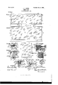
- Figure I is a top plan of a showcase embodying my invention.
- Fig. II is a front side elevation of the same.
- Fig. III is a right-hand end elevation.
- Fig. IV is a vertical section on any one of lines IV IV, Fig. I.
- Fig. V is a vertical section on line V V, Fig. IV, looking inwardly.
- Fig. VI is a vertical section on line VI VI, Fig. IV, looking inwardly.
- Fig. VII is a section of a rear portion of the case on any one of lines VII VII, Figs. II and III.
- Fig. VIII is a vertical section on line VIII VIII', Fig. VII, looking outwardly.
- Fig. II is a front side elevation of the same.
- Fig. III is a right-hand end elevation.
- Fig. IV is a vertical section on any one of lines IV IV, Fig. I.
- Fig. V is a vertical section on line V V
- IX is a vertical section on line IX IX, Fig. VII, looking outwardly.
- Fig. X is a vertical section taken through one of the forward upper corners of the show-case on line X X, Fig. I, or line X X, Fig. XI.
- Fig. XI is a bottom plan in section on line XI XI, Fig. X.
- ct designates the glass top or top plate of the case; b, the glass front or front plate of the case; c c, the glass end plates of the case, and d the base, and e the back of the case, which back comprises a stationary Wooden frame e' and suitably-ap plied sliding doors e2.
- the said doors e2 are only partially shown in Fig.VII,and theframe e is partially shown in Figs. VII and VIII and shown also in dotted lines in Figs. I and III.
- the upright plates l) and c c are placed upon or connected with the base d in any ap pro ved manner.
- the top plate a is connected with the upright plates h and c c at the upper forward corners of the case and is connected with the upper portion of the front plate at any suitable number of points intermediate of the said corners.
- the top plate not only overlaps and rests upon the upper edges of the upright plates, but projects beyond the outer sides of the said upright plates.
- Each fastening devicef for connecting together the front plate and the top plate between the upper forward corners of the case comprises two metallic members f' and f2, overlapping opposite sides, respectively, of the front plate.
- Membersf' and f2 are secured to the top plate in any approved man ner and are formed, preferably, upon and depend from two different narrow metallic pieces f3 and f4, respectively, that are secured to the top of the case by means of a screw g and a nut h.
- said fastening-forming pieces f3 and f4 are arranged one upon the other below the top ct.
- the upper piece f3 extends between the said top and the front plate and transversely of the latter, and the front plate is recessed in its upper edge, as at b', to accommodate the location of the said piece f3 flush with the upper edge of the front plate, so as to avoid interference with the tight fit desired between the top plate and the front.
- the said piece f3 at the outer side of the front plate is provided with a depending flange close to the said plate, which flange forms the member f', already referred to.
- the lower piece]4 at the inner side of the front plate is provided with a depending flange that forms the member f2, to which reference has already been made.
- Flangefz is provided with a lugf, that engages a niche b2, formed in the inner side of the front plate h.
- the two pieces f3 and f4 are perforated vertically, as at f6, to accommodate the ex tension of the screw g therethrough.
- screw has a head g', arranged to engage the upper side of the top plate a, and the nut 7L upon the screw is arranged to engage the un* der side of the lower piece f4.
- the screw-receiving perforation in the lower piece f4 is elongated longitudinally of the said piece to accommodate the longitudinal adjustment of the piece]E4 toward or from the front plate b upon loosening Jthe nut, which adjustment is required to accommodate different thicknesses of front plates in the manufacture of showcases.
- the fastening devicesf brace the front plate and will assist in resisting any force-such for instance, as that of a lateral external push upon the plate.
- the top plate is of course perforated, as at a', to accommodate the location and operation of the screw g.
- the lug f5 prevents upward displacement of or injury to the top plate by any force accidentally or otherwise applied upwardly upon the plates portion that projects beyond the forward. plate b.
- the opposing surfaces of the two pieces]c3 and f4 are provided, preferably,with atongue-andgrooveconnection.
- Thetongue f7 of this connection in the case illustrated is formed upon the lower piece]c4 and engages a shallow groovefg, formed in the under side of the upper piece f3, and the said groove is sufficiently longer than the engaging tongue to accommodate the longitudinal adjustment of the piece f3.
- the said tongue-and-groove connection assists in holding the members]E3 and f4 together.
- the end plates are fastened at their rear ends to the back frame e', and the means preferably employed for the said purpose comprises any suitable number of comparatively small angle-plates le, arranged at suitable intervals vertically of the corners formed between the said frame and plates.
- One wing or arm t" of each angle-plate is secured to the frame e' by a wood-screw Z, and the said frame is at its rear or outer surface recessed, as at e3, to receive the said member k flush with the said surface of the frame.
- the other arm or wing k2 of the-angleplate engages the outer side of the respective end plate c and is provided upon its inner side with a lug k3, that engages a niche c', formed in the outer side of the end plate, that in its rear edge is provided with a recess c2 for accommodating the reception of the angleplates member Za flush with the said edge when the end plate has its said edge iiush with the rear or outer surface of the frame el as is the fact in the preferred -construction illustrated.
- the top plate a is secured near its rear edge at 'm in any approved manner to the frame e of the back.
- the top plate is secured to corner-fasteners 0, employed in fastening together the front plate and end plates.
- a fastener o is provided at the junction of each end plate and the front plate next below the top plate and comprises two angle-plates or jaws 02 and o', engaging the inner sides and outer sides, respectively, of the said upright plates, and a screw 03, that secures the said angle-plates or jaws together and extends through the joint formed between the said upright glass plates.
- the outer jaw or angle-plate 0' is gradually enlarged upwardly to accommodate the formation of a vertical screw-threaded hole o4 in the upper end of the said jaw without detracting from the appearance of the corner-fastener.
- Hole 04 is engaged by a screw o5, that extends into the said hole through the top plate a, that is perforated, as at a2, to accommodate the introduction of the said screw, that at its upper end has a head overlapping Athe upper surface of the top a and holding the said top downwardly upon the upright plates below.
- the projection of the top a beyond the outer sides of the upright plates of the show-case is desirable not only because it beauties the case, but because it forms a guard to prevent or deter persons from bodily striking, leaning against, or touching the upright plates of the case. rlhe formation of this guard renders desirable the location of the top-plate securing screw o5 of each corner-fastener o as near to the edge of the said guard as is practicable and out-side of the case proper, and this object is attained by the construction ⁇ illustrated, wherein the said screw extends into and cooperates with the nut-forming outer jaw o1" angle-plate of the said fastener,
- the outer clamping member has its upper end forming a nut that is engaged by a screw whose head, in conjunc- 1 tion with the said nut, clam ps the top c1, downf wardly upon the upright plates.
- the combination with the front having its upper edge provided with a recess b and having one of its sides provided, near the said edge, with a lateral recess b2, and the top overlapping said edge, of a fastening device engaging the first-mentioned recess and comprising two depending members overlapping opposite sides, respectively, of the front, means securing the said fastening device to the top, and a lug formed upon one of the aforesaid depending members and engaging the aforesaid lateral recess b2.
- the combination with the front plate and the top plate overlapping the upper edge of the front plate of a fastening device arranged at the under side of the top plate and comprising two pieces arranged, one above the other, and one of said pieces being adjustable longitudinally of the other; means securing the said fastening-forming pieces to the top plate and instrumental in securing the adjustable piece in the desired adjustment; flanges formed upon the two different pieces, respectively, of the fastening device and overlapping opposite sides, respectively, of the front plate; atongue-andgroove connection formed between the opposing surfaces of the said pieces, and the groove of the said tongue-and-groove connecton being longer than the tongue to accommodate the longitudinal adjustment of the aforesaid adjustable piece, substantially as shown, for the purpose specified.
- a fastening device for connecting the said plates together at each of the aforesaid recesses, which fastening device is arranged at the under side of and suitably secured to the top plate and comprises two flanged pieces, one of said flanged pieces extending through one of the aforesaid recesses and having its flange overlapping the outer side of the front plate, and the other flanged piece having its flange overlapping the inner side of 'the front plate, substantially as shown, for the purpose specified.
Landscapes
- Assembled Shelves (AREA)
Description
Patented Nov. 6, |900. J. L. CRANE.
SHOW CASE.
(Application tiled Aug. 27, 1899.)
(No Windel.)
13V/ TNE SSE S ma@ AMT @d//f/Mm [mms Pneus co.A PHnro-glruo.. wA
JAMES L. CRANE, OF CLEVELAND, OI'IIO.
snow-CASE'.
srnoiricnrion arming part of Letters Patent No. 661,237, dated November e, leoo.
Application tiled April 27,1899. berial No. 714,667. (No model.)
To @ZZ who-m. it may concern.-
Be it known that I, JAMES L. CRANE, residing at Cleveland, county of Cuyahoga, and State of Ohio, have invented certain new and useful Improvements in Show-Cases; and I do hereby declare the following to be a full, clear, and exact description of the invention, such as will enable others skilled in the art to which it pertains to make and use the same.
My invention relates to improvements in show-cases, and more especially to a showcase that is practically an all-glass case and is known in the trade as an allglass case.
The object of this invention is to provide improved means for bracing and preventing displacement of the glass platesfor instance, to laterally brace or prevent lateral displaceinent of the upright glass plates, to prevent upward displacement of the top plate, and to prevent edgewise displacement of the plates generally.
With this object in view my invention consists in certain features of construction and combinations of parts hereinafter described, and pointed out in the claims.
In the accompanying drawings, Figure I is a top plan of a showcase embodying my invention. Fig. II is a front side elevation of the same. Fig. III is a right-hand end elevation. Fig. IV is a vertical section on any one of lines IV IV, Fig. I. Fig. V is a vertical section on line V V, Fig. IV, looking inwardly. Fig. VI is a vertical section on line VI VI, Fig. IV, looking inwardly. Fig. VII is a section of a rear portion of the case on any one of lines VII VII, Figs. II and III. Fig. VIII is a vertical section on line VIII VIII', Fig. VII, looking outwardly. Fig. IX is a vertical section on line IX IX, Fig. VII, looking outwardly. Fig. X is a vertical section taken through one of the forward upper corners of the show-case on line X X, Fig. I, or line X X, Fig. XI. Fig. XI is a bottom plan in section on line XI XI, Fig. X.
Referring to the drawings, ct designates the glass top or top plate of the case; b, the glass front or front plate of the case; c c, the glass end plates of the case, and d the base, and e the back of the case, which back comprises a stationary Wooden frame e' and suitably-ap plied sliding doors e2. The said doors e2 are only partially shown in Fig.VII,and theframe e is partially shown in Figs. VII and VIII and shown also in dotted lines in Figs. I and III.
The upright plates l) and c c are placed upon or connected with the base d in any ap pro ved manner. The top plate a is connected with the upright plates h and c c at the upper forward corners of the case and is connected with the upper portion of the front plate at any suitable number of points intermediate of the said corners. The top plate not only overlaps and rests upon the upper edges of the upright plates, but projects beyond the outer sides of the said upright plates.
Each fastening devicef for connecting together the front plate and the top plate between the upper forward corners of the case comprises two metallic members f' and f2, overlapping opposite sides, respectively, of the front plate. Membersf' and f2 are secured to the top plate in any approved man ner and are formed, preferably, upon and depend from two different narrow metallic pieces f3 and f4, respectively, that are secured to the top of the case by means of a screw g and a nut h. In the case illustrated t-he said fastening-forming pieces f3 and f4 are arranged one upon the other below the top ct. The upper piece f3 extends between the said top and the front plate and transversely of the latter, and the front plate is recessed in its upper edge, as at b', to accommodate the location of the said piece f3 flush with the upper edge of the front plate, so as to avoid interference with the tight fit desired between the top plate and the front.
plate. The said piece f3 at the outer side of the front plate is provided with a depending flange close to the said plate, which flange forms the member f', already referred to. The lower piece]4 at the inner side of the front plate is provided with a depending flange that forms the member f2, to which reference has already been made. Flangefz is provided with a lugf, that engages a niche b2, formed in the inner side of the front plate h. The two pieces f3 and f4 are perforated vertically, as at f6, to accommodate the ex tension of the screw g therethrough. The
screw has a head g', arranged to engage the upper side of the top plate a, and the nut 7L upon the screw is arranged to engage the un* der side of the lower piece f4.
Upon tight- IOO 2 v sci as ening this nut the screws head will cause the top plate to be tightened upon the upright plates h and c c. The screw-receiving perforation in the lower piece f4 is elongated longitudinally of the said piece to accommodate the longitudinal adjustment of the piece]E4 toward or from the front plate b upon loosening Jthe nut, which adjustment is required to accommodate different thicknesses of front plates in the manufacture of showcases. The fastening devicesf brace the front plate and will assist in resisting any force-such for instance, as that of a lateral external push upon the plate. The top plate is of course perforated, as at a', to accommodate the location and operation of the screw g. The lug f5 prevents upward displacement of or injury to the top plate by any force accidentally or otherwise applied upwardly upon the plates portion that projects beyond the forward. plate b. The opposing surfaces of the two pieces]c3 and f4 are provided, preferably,with atongue-andgrooveconnection. Thetongue f7 of this connection in the case illustrated is formed upon the lower piece]c4 and engages a shallow groovefg, formed in the under side of the upper piece f3, and the said groove is sufficiently longer than the engaging tongue to accommodate the longitudinal adjustment of the piece f3. The said tongue-and-groove connection assists in holding the members]E3 and f4 together.
The end plates are fastened at their rear ends to the back frame e', and the means preferably employed for the said purpose comprises any suitable number of comparatively small angle-plates le, arranged at suitable intervals vertically of the corners formed between the said frame and plates. One wing or arm t" of each angle-plate is secured to the frame e' by a wood-screw Z, and the said frame is at its rear or outer surface recessed, as at e3, to receive the said member k flush with the said surface of the frame. The other arm or wing k2 of the-angleplate engages the outer side of the respective end plate c and is provided upon its inner side with a lug k3, that engages a niche c', formed in the outer side of the end plate, that in its rear edge is provided with a recess c2 for accommodating the reception of the angleplates member Za flush with the said edge when the end plate has its said edge iiush with the rear or outer surface of the frame el as is the fact in the preferred -construction illustrated.
The top plate a is secured near its rear edge at 'm in any approved manner to the frame e of the back. The top plate is secured to corner-fasteners 0, employed in fastening together the front plate and end plates. A fastener ois provided at the junction of each end plate and the front plate next below the top plate and comprises two angle-plates or jaws 02 and o', engaging the inner sides and outer sides, respectively, of the said upright plates, and a screw 03, that secures the said angle-plates or jaws together and extends through the joint formed between the said upright glass plates. The outer jaw or angle-plate 0' is gradually enlarged upwardly to accommodate the formation of a vertical screw-threaded hole o4 in the upper end of the said jaw without detracting from the appearance of the corner-fastener. Hole 04 is engaged by a screw o5, that extends into the said hole through the top plate a, that is perforated, as at a2, to accommodate the introduction of the said screw, that at its upper end has a head overlapping Athe upper surface of the top a and holding the said top downwardly upon the upright plates below.
The projection of the top a beyond the outer sides of the upright plates of the show-case is desirable not only because it beauties the case, but because it forms a guard to prevent or deter persons from bodily striking, leaning against, or touching the upright plates of the case. rlhe formation of this guard renders desirable the location of the top-plate securing screw o5 of each corner-fastener o as near to the edge of the said guard as is practicable and out-side of the case proper, and this object is attained by the construction `illustrated, wherein the said screw extends into and cooperates with the nut-forming outer jaw o1" angle-plate of the said fastener,
, that comprises clamp-forming angle-plates or jaws between which the upright glass plates are clamped, and the outer clamping member has its upper end forming a nut that is engaged by a screw whose head, in conjunc- 1 tion with the said nut, clam ps the top c1, downf wardly upon the upright plates.
What I claim isl. In ashow-case, the coinbination,with the front plate h having its upper edge provided with recesses h extending transversely of the said edge and arranged at suitable intervals longitudinally of the plate, and the top plate overlappingthe said recessed edge of the front plate, of fastening devices engaging the different aforesaid recesses, respectively, and secured to the top plate at the under side of the latter, and each of the said fastening devices having two members depending from the top plate at and overlapping opposite sides, respectively, ofthe front plate, substantially as shown, for the purpose specified.
2. In a show-case, the combination,with the front having its upper edge provided with a recess b and having one of its sides provided, near the said edge, with a lateral recess b2, and the top overlapping said edge, of a fastening device engaging the first-mentioned recess and comprising two depending members overlapping opposite sides, respectively, of the front, means securing the said fastening device to the top, and a lug formed upon one of the aforesaid depending members and engaging the aforesaid lateral recess b2.
TOO
IIO
3. In ashow-case, the combination with the front plate and the top plate overlapping the upper edge of the front plate: of a fastening device arranged at the under side of the top plate and comprising two pieces arranged, one above the other, and one of said pieces being adjustable longitudinally of the other; means securing the said fastening-forming pieces to the top plate and instrumental in securing the adjustable piece in the desired adjustment; flanges formed upon the two different pieces, respectively, of the fastening device and overlapping opposite sides, respectively, of the front plate; atongue-andgroove connection formed between the opposing surfaces of the said pieces, and the groove of the said tongue-and-groove connecton being longer than the tongue to accommodate the longitudinal adjustment of the aforesaid adjustable piece, substantially as shown, for the purpose specified.
a. In a show-case, the combination with the front plate provided, in its upper edge, with recesses arranged at suitable intervals between the ends of the case, and the top plate overlapping the upper edge of the front plate; of a fastening device for connecting the said plates together at each of the aforesaid recesses, which fastening device is arranged at the under side of and suitably secured to the top plate and comprises two flanged pieces, one of said flanged pieces extending through one of the aforesaid recesses and having its flange overlapping the outer side of the front plate, and the other flanged piece having its flange overlapping the inner side of 'the front plate, substantially as shown, for the purpose specified.
5. In a show-case, the combination with the upright front plate, upright end plates, and the tcp plate overlapping the upper edges of the said upright plates and extending beyond the outer sides of the front plate and end plates; of a fastening device located at each upper forward corner of the case and comprising two suitably-connected angle-plates or jaws engaging the inner sides and outer sides, respectively, of the upright plates at the said corners, and the outer jaw being provided with an upright threaded hole in 4its upper end, and a screw extending through the projecting portion of the top plate and engaging the said hole, which screw, at its upper end, has a head that overlaps the outer side of the top plate, substantially as shown, for the purpose specied.
6. In a show-case, the combination with the upright front plate, the top plate and the upright end plates; of a fastening device located at each upper forward corner of the case and comprising two ang1eplates or jaws engaging the inner sides and outer sides, respectively, of the upright plates at the said corner, and the outer jaw being gradually enlarged in thickness toward its upper end; an upright screw-threaded hole formed in the upper end of the outer jaw; a perforation formed in the top plate and registering with the aforesaid screw-threaded hole, and a screw engaging the said screw-threaded hole and extending through the perforation in the top plate and having a head at the outer side of the top plate, substantially as shown, for the purpose specified.
'7. In a showcase, the combination with the back recessed, as at e3, and the end plates c having' the recesses c2 and the niches o'; of the angle-plates 7c having the lugs k3, all arranged and operating,substantially as shown, for the purpose specified.
Signed by me at Cleveland, Ohio, this 21st day of April, 1899.
JAMES L. CRANE.
Witnesses:
C. H. Donna, A. I-I. PARRATT.
Priority Applications (1)
| Application Number | Priority Date | Filing Date | Title |
|---|---|---|---|
| US71466799A US661237A (en) | 1899-04-27 | 1899-04-27 | Show-case. |
Applications Claiming Priority (1)
| Application Number | Priority Date | Filing Date | Title |
|---|---|---|---|
| US71466799A US661237A (en) | 1899-04-27 | 1899-04-27 | Show-case. |
Publications (1)
| Publication Number | Publication Date |
|---|---|
| US661237A true US661237A (en) | 1900-11-06 |
Family
ID=2729801
Family Applications (1)
| Application Number | Title | Priority Date | Filing Date |
|---|---|---|---|
| US71466799A Expired - Lifetime US661237A (en) | 1899-04-27 | 1899-04-27 | Show-case. |
Country Status (1)
| Country | Link |
|---|---|
| US (1) | US661237A (en) |
-
1899
- 1899-04-27 US US71466799A patent/US661237A/en not_active Expired - Lifetime
Similar Documents
| Publication | Publication Date | Title |
|---|---|---|
| US9826828B1 (en) | Cabinet assembly system utilizing cooperating grooved components | |
| US2869953A (en) | Cabinet | |
| US1948602A (en) | Doorframe | |
| US2570850A (en) | Connector for attaching backsplash panels to counter tops | |
| US661237A (en) | Show-case. | |
| US2502166A (en) | Gauge and method for mounting and securing doors | |
| US8875449B2 (en) | Closure system for memorial product | |
| US1330936A (en) | Drawer construction | |
| US1223609A (en) | Pane-fastening. | |
| US1182229A (en) | Box-strike for locks. | |
| US1086392A (en) | Glass-locking device for show-cases. | |
| US1074640A (en) | Glass show-case. | |
| US988900A (en) | Metallic window-sash construction. | |
| US1105502A (en) | Dispensing-refrigerator. | |
| US747148A (en) | Show-front or show-case. | |
| US1002166A (en) | Fireproof window construction. | |
| US837437A (en) | Corner-post, transom-bar, or mullion. | |
| US1379553A (en) | Counter-guard construction | |
| US1009089A (en) | Sheet-metal structure. | |
| US235861A (en) | Billiard-table chuck | |
| US798017A (en) | Corner-post, transom-bar, and the like. | |
| US1042118A (en) | Show-case. | |
| US1009104A (en) | Cellar-door. | |
| US848859A (en) | Striker-plate. | |
| US1130754A (en) | Lock-strike. |