US6591040B1 - Ultra-dense wavelength division multiplexing/demultiplexing devices - Google Patents
Ultra-dense wavelength division multiplexing/demultiplexing devices Download PDFInfo
- Publication number
- US6591040B1 US6591040B1 US10/056,487 US5648702A US6591040B1 US 6591040 B1 US6591040 B1 US 6591040B1 US 5648702 A US5648702 A US 5648702A US 6591040 B1 US6591040 B1 US 6591040B1
- Authority
- US
- United States
- Prior art keywords
- optical
- wavelength division
- multiplexed
- division multiplexing
- polychromatic
- Prior art date
- Legal status (The legal status is an assumption and is not a legal conclusion. Google has not performed a legal analysis and makes no representation as to the accuracy of the status listed.)
- Expired - Lifetime
Links
- 230000003287 optical effect Effects 0.000 claims abstract description 336
- 239000013307 optical fiber Substances 0.000 claims description 47
- 238000000034 method Methods 0.000 claims description 9
- 239000000835 fiber Substances 0.000 description 99
- 230000008878 coupling Effects 0.000 description 58
- 238000010168 coupling process Methods 0.000 description 58
- 238000005859 coupling reaction Methods 0.000 description 58
- 230000005540 biological transmission Effects 0.000 description 10
- 238000003491 array Methods 0.000 description 7
- 238000013461 design Methods 0.000 description 6
- 238000005516 engineering process Methods 0.000 description 6
- 238000001228 spectrum Methods 0.000 description 5
- 230000008901 benefit Effects 0.000 description 4
- 238000012986 modification Methods 0.000 description 4
- 230000004048 modification Effects 0.000 description 4
- 238000013459 approach Methods 0.000 description 3
- 238000000926 separation method Methods 0.000 description 3
- XUIMIQQOPSSXEZ-UHFFFAOYSA-N Silicon Chemical compound [Si] XUIMIQQOPSSXEZ-UHFFFAOYSA-N 0.000 description 2
- 229910052782 aluminium Inorganic materials 0.000 description 2
- XAGFODPZIPBFFR-UHFFFAOYSA-N aluminium Chemical compound [Al] XAGFODPZIPBFFR-UHFFFAOYSA-N 0.000 description 2
- 230000001419 dependent effect Effects 0.000 description 2
- PCHJSUWPFVWCPO-UHFFFAOYSA-N gold Chemical compound [Au] PCHJSUWPFVWCPO-UHFFFAOYSA-N 0.000 description 2
- 229910052737 gold Inorganic materials 0.000 description 2
- 239000010931 gold Substances 0.000 description 2
- 238000003780 insertion Methods 0.000 description 2
- 230000037431 insertion Effects 0.000 description 2
- 239000000463 material Substances 0.000 description 2
- 229910052751 metal Inorganic materials 0.000 description 2
- 239000002184 metal Substances 0.000 description 2
- 229920000642 polymer Polymers 0.000 description 2
- 230000004044 response Effects 0.000 description 2
- 229910052710 silicon Inorganic materials 0.000 description 2
- 239000010703 silicon Substances 0.000 description 2
- 230000000712 assembly Effects 0.000 description 1
- 238000000429 assembly Methods 0.000 description 1
- 230000003796 beauty Effects 0.000 description 1
- 230000015556 catabolic process Effects 0.000 description 1
- 238000006731 degradation reaction Methods 0.000 description 1
- 238000005530 etching Methods 0.000 description 1
- -1 for example Substances 0.000 description 1
- 239000011521 glass Substances 0.000 description 1
- 238000004519 manufacturing process Methods 0.000 description 1
- 238000004806 packaging method and process Methods 0.000 description 1
- 239000002861 polymer material Substances 0.000 description 1
- 238000012545 processing Methods 0.000 description 1
- 230000003362 replicative effect Effects 0.000 description 1
- 238000012360 testing method Methods 0.000 description 1
Images


Classifications
-
- G—PHYSICS
- G02—OPTICS
- G02B—OPTICAL ELEMENTS, SYSTEMS OR APPARATUS
- G02B6/00—Light guides; Structural details of arrangements comprising light guides and other optical elements, e.g. couplings
- G02B6/24—Coupling light guides
- G02B6/26—Optical coupling means
- G02B6/28—Optical coupling means having data bus means, i.e. plural waveguides interconnected and providing an inherently bidirectional system by mixing and splitting signals
- G02B6/293—Optical coupling means having data bus means, i.e. plural waveguides interconnected and providing an inherently bidirectional system by mixing and splitting signals with wavelength selective means
- G02B6/29304—Optical coupling means having data bus means, i.e. plural waveguides interconnected and providing an inherently bidirectional system by mixing and splitting signals with wavelength selective means operating by diffraction, e.g. grating
- G02B6/29305—Optical coupling means having data bus means, i.e. plural waveguides interconnected and providing an inherently bidirectional system by mixing and splitting signals with wavelength selective means operating by diffraction, e.g. grating as bulk element, i.e. free space arrangement external to a light guide
- G02B6/2931—Diffractive element operating in reflection
-
- G—PHYSICS
- G02—OPTICS
- G02B—OPTICAL ELEMENTS, SYSTEMS OR APPARATUS
- G02B27/00—Optical systems or apparatus not provided for by any of the groups G02B1/00 - G02B26/00, G02B30/00
- G02B27/10—Beam splitting or combining systems
- G02B27/1086—Beam splitting or combining systems operating by diffraction only
-
- G—PHYSICS
- G02—OPTICS
- G02B—OPTICAL ELEMENTS, SYSTEMS OR APPARATUS
- G02B6/00—Light guides; Structural details of arrangements comprising light guides and other optical elements, e.g. couplings
- G02B6/24—Coupling light guides
- G02B6/26—Optical coupling means
- G02B6/28—Optical coupling means having data bus means, i.e. plural waveguides interconnected and providing an inherently bidirectional system by mixing and splitting signals
- G02B6/293—Optical coupling means having data bus means, i.e. plural waveguides interconnected and providing an inherently bidirectional system by mixing and splitting signals with wavelength selective means
- G02B6/29304—Optical coupling means having data bus means, i.e. plural waveguides interconnected and providing an inherently bidirectional system by mixing and splitting signals with wavelength selective means operating by diffraction, e.g. grating
- G02B6/29305—Optical coupling means having data bus means, i.e. plural waveguides interconnected and providing an inherently bidirectional system by mixing and splitting signals with wavelength selective means operating by diffraction, e.g. grating as bulk element, i.e. free space arrangement external to a light guide
- G02B6/29311—Diffractive element operating in transmission
-
- G—PHYSICS
- G02—OPTICS
- G02B—OPTICAL ELEMENTS, SYSTEMS OR APPARATUS
- G02B6/00—Light guides; Structural details of arrangements comprising light guides and other optical elements, e.g. couplings
- G02B6/24—Coupling light guides
- G02B6/26—Optical coupling means
- G02B6/28—Optical coupling means having data bus means, i.e. plural waveguides interconnected and providing an inherently bidirectional system by mixing and splitting signals
- G02B6/293—Optical coupling means having data bus means, i.e. plural waveguides interconnected and providing an inherently bidirectional system by mixing and splitting signals with wavelength selective means
- G02B6/29379—Optical coupling means having data bus means, i.e. plural waveguides interconnected and providing an inherently bidirectional system by mixing and splitting signals with wavelength selective means characterised by the function or use of the complete device
- G02B6/2938—Optical coupling means having data bus means, i.e. plural waveguides interconnected and providing an inherently bidirectional system by mixing and splitting signals with wavelength selective means characterised by the function or use of the complete device for multiplexing or demultiplexing, i.e. combining or separating wavelengths, e.g. 1xN, NxM
-
- H—ELECTRICITY
- H04—ELECTRIC COMMUNICATION TECHNIQUE
- H04J—MULTIPLEX COMMUNICATION
- H04J14/00—Optical multiplex systems
- H04J14/02—Wavelength-division multiplex systems
Definitions
- the present invention relates generally to wavelength division multiplexing and demultiplexing and, more particularly, to ultra-dense wavelength division multiplexing/demultiplexing devices.
- Wavelength division multiplexing is a rapidly emerging technology that enables a very significant increase in the aggregate volume of data that can be transmitted over optical fibers.
- WDM Wavelength division multiplexing
- the basic concept of WDM is to launch and retrieve multiple data channels in and out, respectively, of an optical fiber. Each data channel is transmitted at a unique wavelength, and the wavelengths are appropriately selected such that the channels do not interfere with each other, and the optical transmission losses of the fiber are low.
- WDM is a cost-effective method of increasing the volume of data (commonly termed bandwidth) transferred over optical fibers.
- Alternate competing technologies for increasing bandwidth include the burying of additional fiber optic cable or increasing the optical transmission rate over optical fiber.
- the burying of additional fiber optic cable is quite costly as it is presently on the order of $15,000 to $40,000 per kilometer.
- Increasing the optical transmission rate is limited by the speed and economy of the electronics surrounding the fiber optic system.
- TDM time division multiplexing
- WDM offers the potential of both an economical and technological solution to increasing bandwidth by using many parallel channels.
- WDM is complimentary to TDM. That is, WDM can allow many simultaneous high transmission rate TDM channels to be passed over a single optical fiber.
- the use of WDM to increase bandwidth requires two basic devices that are conceptually symmetrical.
- the first device is a wavelength division multiplexer. This device takes multiple beams, each with discrete wavelengths that are initially spatially separated in space, and provides a means for spatially combining all of the different wavelength beams into a single polychromatic beam suitable for launching into an optical fiber.
- the multiplexer may be a completely passive optical device or may include electronics that control or monitor the performance of the multiplexer.
- the input to the multiplexer is typically accomplished with optical fibers, although laser diodes or other optical sources may also be employed.
- the output from the multiplexer is a single polychromatic beam which is typically directed into an optical fiber.
- the second device for WDM is a wavelength division demultiplexer.
- This device is functionally the opposite of the wavelength division multiplexer. That is, the wavelength division demultiplexer receives a polychromatic beam from an optical fiber and provides a means of spatially separating the different wavelengths of the polychromatic beam.
- the output from the demultiplexer is a plurality of monochromatic beams which are typically directed into a corresponding plurality of optical fibers or photodetectors.
- WDM devices have been directed toward multiplexing or demultiplexing a standard number of data channels.
- many WDM devices are specifically manufactured to multiplex 33 individual data channels being carried on 33 corresponding monochromatic beams into a single polychromatic beam carrying all 33 data channels, or to demultiplex a single polychromatic beam carrying 33 separate data channels into 33 individual monochromatic beams each carrying a corresponding data channel.
- These WDM devices are typically limited to 33 data channels due to the manner in which they have been manufactured and the technologies employed to perform the multiplexing and demultiplexing functions therein.
- WDM devices employing fiber Bragg gratings and/or array waveguide gratings to perform multiplexing and demultiplexing functions are typically limited to the number of data channels that the WDM devices were specifically manufactured to handle.
- additional WDM devices are required, at a corresponding additional cost.
- enhanced WDM devices employing these technologies may be designed to accommodate additional numbers of data channels, but with corresponding additional design, manufacturing, and testing costs.
- such enhanced WDM devices are typically larger in size so as to accommodate the increased number of data channels, thereby requiring more space to operate, which usually translates into additional packaging costs.
- the primary object of the present invention is to provide ultra-dense wavelength division multiplexing/demultiplexing devices.
- ultra-dense wavelength division multiplexing/demultiplexing devices are provided.
- a wavelength division multiplexing device is used for combining at least one plurality of monochromatic optical beams into a corresponding at least one single, multiplexed, polychromatic optical beam, wherein the wavelength division multiplexing device has an input element and an output element.
- a plurality of optical input devices is disposed proximate the input element, wherein each of the plurality of optical input devices communicates a plurality of monochromatic optical beams to the wavelength division multiplexing device for combining the plurality of monochromatic optical beams into a single, multiplexed, polychromatic optical beam.
- a corresponding plurality of optical output devices is disposed proximate the output element, wherein each of the plurality of optical output devices receives a corresponding single, multiplexed, polychromatic optical beam.
- the wavelength division multiplexing device comprises a diffraction grating for combining the at least one plurality of monochromatic optical beams into the corresponding at least one single, multiplexed, polychromatic optical beam.
- the diffraction grating is preferably a reflective diffraction grating oriented at the Littrow diffraction angle.
- the diffraction grating can be a transmissive diffraction grating.
- the input element can beneficially be one of several items such as, for example, a collimating lens or a boot lens.
- the output element can beneficially be one of several items such as, for example, a focusing lens or a boot lens.
- the plurality of optical input devices is beneficially a plurality of input fiber coupling devices, wherein each of the plurality of input fiber coupling devices is arranged into an array of optical fibers, and each of the optical fibers transmits a monochromatic optical beam to the wavelength division multiplexing device.
- the plurality of optical input devices is beneficially a plurality of laser diode coupling devices, wherein each of the plurality of laser diode coupling devices is arranged into an array of laser diodes, and each of the laser diodes transmits a monochromatic optical beam to the wavelength division multiplexing device.
- the plurality of optical output devices is beneficially a plurality of output fiber coupling devices, wherein each of the plurality of output fiber coupling devices maintains at least one optical fiber, and each optical fiber receives a single, multiplexed, polychromatic optical beam from the wavelength division multiplexing device.
- a wavelength division demultiplexing device is used for separating at least one multiplexed, polychromatic optical beam into a corresponding at least one plurality of monochromatic optical beams, wherein the wavelength division demultiplexing device has an input element and an output element.
- a plurality of optical input devices is disposed proximate the input element, wherein each of the plurality of optical input devices communicates a single, multiplexed, polychromatic optical beam to the wavelength division demultiplexing device for separating the single, multiplexed, polychromatic optical beam into a plurality of monochromatic optical beams.
- a corresponding plurality of optical output devices is disposed proximate the output element, wherein each of the plurality of optical output devices receives a corresponding plurality of monochromatic optical beams.
- the wavelength division demultiplexing device comprises a diffraction grating for separating the at least one multiplexed, polychromatic optical beam into the corresponding at least one plurality of monochromatic optical beams.
- the diffraction grating is preferably a reflective diffraction grating oriented at the Littrow diffraction angle.
- the diffraction grating can be a transmissive diffraction grating.
- the input element can beneficially be one of several items such as, for example, a collimating lens or a boot lens.
- the output element can beneficially be one of several items such as, for example, a focusing lens or a boot lens.
- the plurality of optical input devices is beneficially a plurality of input fiber coupling devices, wherein each of the plurality of input fiber coupling devices maintains at least one optical fiber, and each optical fiber transmits a single, multiplexed, polychromatic optical beam to the wavelength division demultiplexing device.
- the plurality of optical output devices is beneficially a plurality of output fiber coupling devices, wherein each of the plurality of output fiber coupling devices is arranged into an array of optical fibers, and each of the optical fibers receives a monochromatic optical beam from the wavelength division demultiplexing device.
- the plurality of optical output devices is beneficially a plurality of photodetector coupling devices, wherein each of the plurality of photodetector coupling devices is arranged into an array of photodetectors, and each of the photodetectors receives a monochromatic optical beam from the wavelength division demultiplexing device.
- the at least one multiplexed, polychromatic optical beam can be at least two multiplexed, polychromatic optical beams.
- the ultra-dense wavelength division demultiplexing device may further comprise a splitter for splitting a single, pre-split, multiplexed, polychromatic optical beam into the at least two multiplexed, polychromatic optical beams.
- the single, pre-split, multiplexed, polychromatic optical beam can be split equally or unequally.
- the single, pre-split, multiplexed, polychromatic optical beam can be split in several manners such as, for example, according to beam wavelengths or according to beam intensity.
- the present invention also encompasses a method for increasing channel throughput in a wavelength division demultiplexing device.
- the method comprises splitting a single, multiplexed, polychromatic optical beam into at least two multiplexed, polychromatic optical beams, and then simultaneously separating each of the at least two multiplexed, polychromatic optical beams into a corresponding at least two pluralities of monochromatic optical beams.
- the method also preferably comprises collimating each of the at least two multiplexed, polychromatic optical beams, and focusing the corresponding at least two pluralities of monochromatic optical beams.
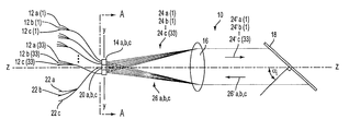
- FIG. 1 a is a side view of an ultra-dense wavelength division multiplexing devise having a plurality of optical input devices and a plurality of optical output devices in accordance with the present invention.
- FIG. 1 b is a top view of the ultra-dense wavelength division multiplexing device shown in FIG. 1 a.
- FIG. 1 c is an end view of a portion of the ultra-dense wavelength division multiplexing device shown in FIG. 1 a.
- FIG. 2 a is a perspective view of a coupling device containing a plurality of laser diodes for replacing the plurality of optical input fibers in the multiplexing device shown in FIG. 1 a.
- FIG. 2 b is a perspective view of a coupling device containing a plurality of photodetectors for replacing the plurality of optical input fibers in the demultiplexing device shown in FIG. 3 a.
- FIG. 3 a is a side view of an ultra-dense wavelength division demultiplexing device having a plurality of optical input devices and a plurality of optical output devices in accordance with the present invention.
- FIG. 3 b is a top view of the ultra-dense wavelength division demultiplexing device shown in FIG. 3 a.
- FIG. 4 is a top view of a demultiplexing system employing an ultra-dense wavelength division demultiplexing device having a plurality of optical input devices and a plurality of optical output devices in accordance with the present invention.
- the multiplexing device 10 comprises a plurality of optical input fibers 12 , a plurality of input fiber coupling devices 14 , a collimating/focusing lens 16 , a reflective diffraction grating 18 , a plurality of output fiber coupling devices 20 , and a plurality of optical output fibers 22 . All of the above-identified components of the multiplexing device 10 are disposed along an optical axis Z-Z of the multiplexing device 10 , as will be described in more detail below.
- optical input fibers 12 and the optical output fibers 22 are single mode optical fibers.
- the present invention WDM devices can also be used with multimode optical fibers.
- the plurality of optical input fibers 12 are grouped into three one-dimensional input fiber arrays (i.e., three 1 ⁇ 33 arrays) by the plurality of input fiber coupling devices 14 , while each of the plurality of optical output fibers 22 is secured to a corresponding one of the plurality of output fiber coupling devices 20 .
- Both the input fiber coupling devices 14 and the output fiber coupling devices 20 are used for purposes of ease of optical fiber handling and precision placement, and can be formed of, for example, silicon V-groove assemblies. Referring to FIG. 1 c, there is shown an end view of the plurality of input fiber coupling devices 14 and the plurality of output fiber coupling devices 20 , along section A-A of FIGS. 1 a and 1 b.
- Each of the plurality of input fiber coupling devices 14 is arranged as a 1 ⁇ 33 array for precisely and securely positioning thirty-three of the plurality of optical input fibers 12 , while each of the plurality of output fiber coupling devices 20 precisely and securely positions a corresponding one of the plurality of optical output fibers 22 .
- each of the plurality of optical input fibers 12 transmits a single, monochromatic optical input beam 24
- each of the plurality of optical output fibers 22 receives a single, multiplexed, polychromatic optical output beam 26 .
- Each of the monochromatic optical input beams 24 being transmitted from the plurality of optical input fibers 12 is carrying a single channel of data at a unique wavelength, which is preferably, but not required to be, within the infrared (IR) region of the electromagnetic spectrum.
- each monochromatic optical input beam 24 is superimposed on each corresponding unique wavelength by means (e.g., laser diodes connected to the plurality of optical input fibers 12 ), which are not shown here and which do not form a part of this invention, but are well known in the art.
- the unique wavelengths of the monochromatic optical input beams 24 are appropriately preselected such that the data channels do not interfere with each other (i.e., there is sufficient channel spacing), and the optical transmission losses through both the optical input fibers 12 and the optical output fibers 22 are low, as is also well known in the art.
- Each of the multiplexed, polychromatic optical output beams 26 being received by the plurality of optical output fibers 22 is carrying a plurality of channels of data at the unique wavelengths of corresponding ones of the plurality of monochromatic optical input beams 24 . That is, a first of the multiplexed, polychromatic optical output beams 26 a is carrying a plurality of channels of data (e.g., 33 channels of data) at the unique wavelengths of the monochromatic optical input beams 24 a that are transmitted from the optical input fibers 12 a being precisely and securely positioned by a first of the plurality of input fiber coupling devices 14 a.
- a plurality of channels of data e.g., 33 channels of data
- a second of the multiplexed, polychromatic optical output beams 26 b is carrying a plurality of channels of data (e.g., 33 channels of data) at the unique wavelengths of the monochromatic optical input beams 24 b that are transmitted from the optical input fibers 12 b being precisely and securely positioned by a second of the plurality of input fiber coupling devices 14 b.
- a plurality of channels of data e.g., 33 channels of data
- a third of the multiplexed, polychromatic optical output beams 26 c is carrying a plurality of channels of data (e.g., 33 channels of data) at the unique wavelengths of the monochromatic optical input beams 24 c that are transmitted from the optical input fibers 12 c being precisely and securely positioned by a third of the plurality of input fiber coupling devices 14 c.
- a plurality of channels of data e.g., 33 channels of data
- the plurality of monochromatic optical input beams 24 a are combined into the multiplexed, polychromatic optical output beam 26 a through the combined operation of the collimating/focusing lens 16 and the reflective diffraction grating 18 , as will be described in more detail below.
- the plurality of monochromatic optical input beams 24 b are combined into the multiplexed, polychromatic optical output beam 26 b through the combined operation of the collimating/focusing lens 16 and the reflective diffraction grating 18 , as will be described in more detail below.
- the plurality of monochromatic optical input beams 24 c are combined into the multiplexed, polychromatic optical output beam 26 c through the combined operation of the collimating/focusing lens 16 and the reflective diffraction grating 18 , as will be described in more detail below.
- the input fiber coupling device 14 a and the output fiber coupling device 20 a are disposed offset from, but symmetrically about, the optical axis Z-Z of the multiplexing device 10 so as to insure that the multiplexed, polychromatic optical output beam 26 a is directed to the optical output fiber 22 a secured to the output fiber coupling device 20 a, and not to any of the other optical output fibers 22 , or anywhere else.
- This offset spacing of the input fiber coupling device 14 a and the output fiber coupling device 20 a is determined based upon the focusing power of the collimating/focusing lens 16 , as well as the characteristics of the diffraction grating 18 and the wavelengths of each of the monochromatic optical input beams 24 a.
- the input fiber coupling device 14 b and the output fiber coupling device 20 b are disposed offset from, but symmetrically about, the optical axis Z-Z of the multiplexing device 10 so as to insure that the multiplexed, polychromatic optical output beam 26 b is directed to the optical output fiber 22 b secured to the output fiber coupling device 20 b, and not to any of the other optical output fibers 22 , or anywhere else.
- This offset spacing of the input fiber coupling device 14 b and the output fiber coupling device 20 b is determined based upon the focusing power of the collimating/focusing lens 16 , as well as the characteristics of the diffraction grating 18 and the wavelengths of each of the monochromatic optical input beams 24 b.
- the input fiber coupling device 14 c and the output fiber coupling device 20 c are disposed offset from, but symmetrically about, the optical axis Z-Z of the multiplexing device 10 so as to insure that the multiplexed, polychromatic optical output beam 26 c is directed to the optical output fiber 22 c secured to the output fiber coupling device 20 c, and not to any of the other optical output fibers 22 , or anywhere else.
- This offset spacing of the input fiber coupling device 14 c and the output fiber coupling device 20 c is determined based upon the focusing power of the collimating/focusing lens 16 , as well as the characteristics of the diffraction grating 18 and the wavelengths of each of the monochromatic optical input beams 24 c.
- Each of the plurality of monochromatic optical input beams 24 are transmitted from their corresponding optical input fiber 12 into the air space between the plurality of input fiber coupling devices 14 and the collimating/focusing lens 16 . Within this air space, the plurality of monochromatic optical input beams 24 are expanded in diameter until they become incident upon the collimating/focusing lens 16 . The collimating/focusing lens 16 collimates each of the plurality of monochromatic optical input beams 24 , and then transmits each collimated, monochromatic optical input beam 24 ′ to the reflective diffraction grating 18 .
- the optical axis of the collimating/focusing lens 16 coincides with the optical axis Z-Z of the multiplexing device 10 so as to insure that the multiplexed, polychromatic optical output beam 26 a is directed to the optical output fiber 22 a secured to the output fiber coupling device 20 a, and not to any of the other optical output fibers 22 , or anywhere else, as will be described in more detail below.
- the optical axis of the collimating/focusing lens 16 coincides with the optical axis Z-Z of the multiplexing device 10 so as to insure that the multiplexed, polychromatic optical output beam 26 b is directed to the optical output fiber 22 b secured to the output fiber coupling device 20 b, and not to any of the other optical output fibers 22 , or anywhere else, as will be described in more detail below.
- the optical axis of the collimating/focusing lens 16 coincides with the optical axis Z-Z of the multiplexing device 10 so as to insure that the multiplexed, polychromatic optical output beam 26 c is directed to the optical output fiber 22 c secured to the output fiber coupling device 20 c, and not to any of the other optical output fibers 22 , or anywhere else, as will be described in more detail below.
- the reflective diffraction grating 18 operates to angularly disperse the plurality of collimated, monochromatic optical input beams 24 ′ by an amount that is dependent upon the wavelength of each of the plurality of collimated, monochromatic optical input beams 24 ′. Also, the reflective diffraction grating 18 is oriented at a special angle (i.e., the Littrow diffraction angle, ⁇ i ) relative to the optical axis Z-Z of the multiplexing device 10 in order to obtain the Littrow diffraction condition for an optical beam having a wavelength that lies within or near the wavelength range of the plurality of collimated, monochromatic optical input beams 24 ′.
- a special angle i.e., the Littrow diffraction angle, ⁇ i
- the Littrow diffraction condition requires that an optical beam be incident on and reflected back from a reflective diffraction grating at the exact same angle. Therefore, it will be readily apparent to one skilled in the art that the reflective diffraction grating 18 is used to obtain near-Littrow diffraction for each of the plurality of collimated, monochromatic optical input beams 24 ′.
- the Littrow diffraction angle, ⁇ i is determined by the well-known diffraction grating equation,
- ⁇ i is the common angle of incidence and reflection.
- variables affecting the Littrow diffraction angle, ⁇ i include the desired grating diffraction order, the grating blaze angle, the number of data channels, the spacing of the data channels, and the wavelength range of the multiplexing device 10 .
- the reflective diffraction grating 18 can be formed from a variety of materials and by a variety of techniques.
- the reflective diffraction grating 18 can be formed by a three-dimensional hologram in a polymer medium, or by replicating a mechanically ruled master with a polymer material. In both cases, the polymer is overcoated with a thin, highly reflective metal layer such as, for example, gold or aluminum.
- the reflective diffraction grating 18 can be formed by chemically etching into a planar material such as, for example, glass or silicon, which is also overcoated with a thin, highly reflective metal layer such as, for example, gold or aluminum.
- the reflective diffraction grating 18 operates to angularly disperse the plurality of collimated, monochromatic optical input beams 24 ′.
- the reflective diffraction grating 18 removes the angular separation of the plurality of collimated, monochromatic optical input beams 24 ′ a, and reflects a collimated, polychromatic optical output beam 26 ′ a back towards the collimating/focusing lens 16 .
- the collimated, polychromatic optical output beam 26 ′ a contains each of the unique wavelengths of the plurality of collimated, monochromatic optical input beams 24 ′ a.
- the collimated, polychromatic optical output beam 26 ′ a is a collimated, multiplexed, polychromatic optical output beam 26 ′ a.
- the collimating/focusing lens 16 focuses the collimated, multiplexed, polychromatic optical output beam 26 ′ a, and then transmits the resulting multiplexed, polychromatic optical output beam 26 a to the output fiber coupling device 20 a where it becomes incident upon the optical output fiber 22 a.
- the multiplexed, polychromatic optical output beam 26 a is then coupled into the optical output fiber 22 a for transmission therethrough.
- the reflective diffraction grating 18 removes the angular separation of the plurality of collimated, monochromatic optical input beams 24 ′ b, and reflects a collimated, polychromatic optical output beam 26 ′ b back towards the collimating/focusing lens 16 .
- the collimated, polychromatic optical output beam 26 ′ b contains each of the unique wavelengths of the plurality of collimated, monochromatic optical input beams 24 ′ b.
- the collimated, polychromatic optical output beam 26 ′ b is a collimated, multiplexed, polychromatic optical output beam 26 ′ b.
- the collimating/focusing lens 16 focuses the collimated, multiplexed, polychromatic optical output beam 26 ′ b, and then transmits the resulting multiplexed, polychromatic optical output beam 26 b to the output fiber coupling device 20 b where it becomes incident upon the optical output fiber 22 b.
- the multiplexed, polychromatic optical output beam 26 b is then coupled into the optical output fiber 22 ba for transmission therethrough.
- the reflective diffraction grating 18 removes the angular separation of the plurality of collimated, monochromatic optical input beams 24 ′ c, and reflects a collimated, polychromatic optical output beam 26 ′ c back towards the collimating/focusing lens 16 .
- the collimated, polychromatic optical output beam 26 ′ c contains each of the unique wavelengths of the plurality of collimated, monochromatic optical input beams 24 ′ c.
- the collimated, polychromatic optical output beam 26 ′ c is a collimated, multiplexed, polychromatic optical output beam 26 ′ c.
- the collimating/focusing lens 16 focuses the collimated, multiplexed, polychromatic optical output beam 26 ′ c, and then transmits the resulting multiplexed, polychromatic optical output beam 26 c to the output fiber coupling device 20 c where it becomes incident upon the optical output fiber 22 c.
- the multiplexed, polychromatic optical output beam 26 c is then coupled into the optical output fiber 22 c for transmission therethrough.
- the plurality of optical input fibers 12 could be replaced in the multiplexing device 10 by a corresponding plurality of laser diodes 28 secured within a plurality of coupling devices 30 , such as shown in FIG. 2 a (although FIG. 2 a shows only a single 1 ⁇ 4 array).
- the coupling device 30 performs a similar function to that of each of the plurality of input fiber coupling devices 14 , that being to precisely group the plurality of laser diodes 28 into a one-dimensional input array.
- the plurality of laser diodes 28 are used in place of the plurality of optical input fibers 12 to transmit the plurality of monochromatic optical input beams 24 to the multiplexing device 10 .
- the array of laser diodes 28 , as well as the plurality of optical input fibers 12 may operate alone, or may be used with appropriate focusing lenses (not shown) to provide the best coupling and the lowest amount of signal loss and channel crosstalk.
- the multiplexing device 10 may be operated in a converse configuration as a demultiplexing device 40 , such as shown in FIGS. 3 a and 3 b.
- the demultiplexing device 40 is physically identical to the multiplexing device 10 , and is therefore numerically identified as such. However, the demultiplexing device 40 is functionally opposite to the multiplexing device 10 .
- a plurality of multiplexed, polychromatic optical input beams 42 are transmitted from the plurality of optical fibers 22 , and a plurality of monochromatic optical output beams 44 are transmitted to the plurality of optical fibers 12 , wherein each one of the plurality of monochromatic optical output beams 44 is transmitted to a corresponding one of the plurality of optical fibers 12 .
- the multiplexed, polychromatic optical input beam 42 a is simultaneously carrying a plurality of channels of data, each at a unique wavelength which is preferably, but not required to be, within the infrared (IR) region of the electromagnetic spectrum.
- the plurality of monochromatic optical output beams 44 a are each carrying a single channel of data at a corresponding one of the unique wavelengths of the multiplexed, polychromatic optical input beam 42 a.
- the multiplexed, polychromatic optical input beam 42 a is separated into the plurality of monochromatic optical output beams 44 a through the combined operation of the collimating/focusing lens 16 and the reflective diffraction grating 18 .
- the collimating/focusing lens 16 and the reflective diffraction grating 18 operate to perform a demultiplexing function.
- the multiplexed, polychromatic optical input beam 42 b is simultaneously carrying a plurality of channels of data, each at a unique wavelength which is preferably, but not required to be, within the infrared (IR) region of the electromagnetic spectrum.
- the plurality of monochromatic optical output beams 44 b are each carrying a single channel of data at a corresponding one of the unique wavelengths of the multiplexed, polychromatic optical input beam 42 b.
- the multiplexed, polychromatic optical input beam 42 b is separated into the plurality of monochromatic optical output beams 44 b through the combined operation of the collimating/focusing lens 16 and the reflective diffraction grating 18 .
- the collimating/focusing lens 16 and the reflective diffraction grating 18 operate to perform a demultiplexing function.
- the multiplexed, polychromatic optical input beam 42 c is simultaneously carrying a plurality of channels of data, each at a unique wavelength which is preferably, but not required to be, within the infrared (IR) region of the electromagnetic spectrum.
- the plurality of monochromatic optical output beams 44 c are each carrying a single channel of data at a corresponding one of the unique wavelengths of the multiplexed, polychromatic optical input beam 42 c.
- the multiplexed, polychromatic optical input beam 42 c is separated into the plurality of monochromatic optical output beams 44 c through the combined operation of the collimating/focusing lens 16 and the reflective diffraction grating 18 .
- the collimating/focusing lens 16 and the reflective diffraction grating 18 operate to perform a demultiplexing function.
- the plurality of optical fibers 12 could be replaced in the demultiplexing device 40 by a corresponding plurality of photodetectors 48 secured within a plurality of coupling devices 50 , such as shown in FIG. 2 b (although FIG. 2 b shows only a single 1 ⁇ 13 array).
- the coupling device 50 performs a similar function to that of each of the plurality of fiber coupling devices 14 , that being to precisely group the plurality of photodetectors 48 into a one-dimensional input array.
- the plurality of photodetectors 48 are used in place of the plurality of optical fibers 12 to receive the plurality of monochromatic optical output beams 44 from the demultiplexing device 40 .
- the array of photodetectors 48 , as well as the plurality of optical fibers 12 may operate alone, or may be used with appropriate focusing lenses (not shown) to provide the best coupling and the lowest amount of signal loss and channel crosstalk.
- FIG. 4 there is shown a demultiplexing system 60 wherein the demultiplexing device 40 of FIGS. 3 a and 3 b is used in a practical manner to demultiplex additional data channels without requiring additional WDM devices or significant design modifications in accordance with the present invention.
- the demultiplexing system 60 is physically identical to the multiplexing device 40 , except for the addition of optical input fiber 62 and optical filter 64 , and is therefore numerically identified as such.
- the optical input fiber 62 communicates a single, multiplexed, polychromatic optical input beam to the optical filter 64 .
- the single, multiplexed, polychromatic optical input beam being communicated by the optical input fiber 62 is simultaneously carrying a plurality of channels of data (e.g., 99 channels of data), each at a unique wavelength which is preferably, but not required to be, within the infrared (IR) region of the electromagnetic spectrum.
- the optical filter 64 equally splits the single, multiplexed, polychromatic optical input beam according to wavelength into three multiplexed, polychromatic optical input beams 42 .
- each of the three resulting multiplexed, polychromatic optical input beams 42 is simultaneously carrying a plurality of channels of data (e.g., 33 channels of data) at the unique wavelengths of corresponding ones of the unique wavelengths of the single, multiplexed, polychromatic optical input beam.
- the multiplexed, polychromatic optical input beam 42 a is simultaneously carrying a plurality of channels of data (e.g., 33 channels of data) at the unique wavelengths of corresponding ones of the unique wavelengths of the single, multiplexed, polychromatic optical input beam.
- the plurality of monochromatic optical output beams 44 a are each carrying a single channel of data at a corresponding one of the unique wavelengths of the multiplexed, polychromatic optical input beam 42 a.
- the multiplexed, polychromatic optical input beam 42 a is separated into the plurality of monochromatic optical output beams 44 a through the combined operation of the collimating/focusing lens 16 and the reflective diffraction grating 18 .
- the collimating/focusing lens 16 and the reflective diffraction grating 18 operate to perform a demultiplexing function.
- the multiplexed, polychromatic optical input beam 42 b is simultaneously carrying a plurality of channels of data (e.g., 33 channels of data) at the unique wavelengths of corresponding ones of the unique wavelengths of the single, multiplexed, polychromatic optical input beam.
- the plurality of monochromatic optical output beams 44 b are each carrying a single channel of data at a corresponding one of the unique wavelengths of the multiplexed, polychromatic optical input beam 42 b.
- the multiplexed, polychromatic optical input beam 42 b is separated into the plurality of monochromatic optical output beams 44 b through the combined operation of the collimating/focusing lens 16 and the reflective diffraction grating 18 .
- the collimating/focusing lens 16 and the reflective diffraction grating 18 operate to perform a demultiplexing function.
- the multiplexed, polychromatic optical input beam 42 c is simultaneously carrying a plurality of channels of data (e.g., 33 channels of data) at the unique wavelengths of corresponding ones of the unique wavelengths of the single, multiplexed, polychromatic optical input beam.
- the plurality of monochromatic optical output beams 44 c are each carrying a single channel of data at a corresponding one of the unique wavelengths of the multiplexed, polychromatic optical input beam 42 c.
- the multiplexed, polychromatic optical input beam 42 c is separated into the plurality of monochromatic optical output beams 44 c through the combined operation of the collimating/focusing lens 16 and the reflective diffraction grating 18 .
- the collimating/focusing lens 16 and the reflective diffraction grating 18 operate to perform a demultiplexing function.
- the single, multiplexed, polychromatic optical input beam could be split unequally according to wavelength.
- the single, multiplexed, polychromatic optical input beam could be split either equally or unequally according to beam intensity.
- the single, multiplexed, polychromatic optical input beam could be split such that any or all of the resultant multiplexed, polychromatic optical input beams are identical so as to create redundant channels.
- the single, multiplexed, polychromatic optical input beam could be split such that certain data channels are routed separately so as to provide security as to those data channels.
- the optical filter 64 could be, for example, a standard coupler, a fiber Bragg grating, an interference filter, a bandpass filter, a power splitter, or any other suitable splitting means.
- an ultra-dense wavelength division multiplexing/demultiplexing device in accordance with the present invention may be wholly or partially integrated, and different types of lenses and lens configurations may be used.
- the maximum number of arrays is only dependent upon the ability of the lens design to handle more than one array. Specifically, this relates to a basic tradeoff in performance as arrays are stacked next to one another. The farther away an array is placed from the optical axis Z-Z of the device, typically there is a degradation in fiber coupling efficiency since the lens cannot typically perform at very large field heights with high efficiency. Also, as arrays are placed away from the optical axis Z-Z of the device, there is an increased probability of crosstalk. However, by careful lens design, the performance of each array can be made to be the same as other arrays. For example, the inner-most array can be made to have the same performance as the outermost array.
- the placement of the arrays can be such that there is a non-flat, or unusual response (efficiency versus wavelength).
- the beauty of the present invention approach is that there is no significant insertion loss for creating a WDM device with very high data channel counts. This approach allows processing of more data channels in a more efficient manner than other WDM technologies such as, for example, fiber Bragg gratings or array waveguide gratings (AWGs). Also, the robustness of this approach allows a very large number of data channels to be processed (multiplexed or demultiplexed) in one single WDM device.
- the present invention ultra-dense wavelength division multiplexing/demultiplexing device has the benefits of low insertion loss, low crosstalk, low cost, and a very high number of data channels. More specifically, the present invention ultra-dense wavelength division multiplexing/demultiplexing device offers the new and non-obvious advantages of: (1) the ability to increase the data channel throughput (# of data channels) in a WDM device by simply splitting a signal and then attaching corresponding split signal optical fibers to extra input and output positions on the WDM device; (2) the ability to use a WDM device for the multiplexing or demultiplexing for more than one array of data channels without major changes to the lens design of the WDM device; (3) the ability to use a WDM device for bi-directional and simultaneous multiplexing and demultiplexing (use as a duplex mux/demux); (4) the ability to create a redundant or secure WDM device; and (5) the other new and non-obvious advantages that are apparent from the foregoing description.
Landscapes
- Physics & Mathematics (AREA)
- General Physics & Mathematics (AREA)
- Optics & Photonics (AREA)
- Engineering & Computer Science (AREA)
- Computer Networks & Wireless Communication (AREA)
- Signal Processing (AREA)
- Optical Communication System (AREA)
Abstract
Description
Claims (34)
Priority Applications (1)
| Application Number | Priority Date | Filing Date | Title |
|---|---|---|---|
| US10/056,487 US6591040B1 (en) | 1999-02-25 | 2002-01-28 | Ultra-dense wavelength division multiplexing/demultiplexing devices |
Applications Claiming Priority (11)
| Application Number | Priority Date | Filing Date | Title |
|---|---|---|---|
| US09/257,045 US6137933A (en) | 1997-12-13 | 1999-02-25 | Integrated bi-directional dual axial gradient refractive index/diffraction grating wavelength division multiplexer |
| US09/323,094 US6263135B1 (en) | 1997-12-13 | 1999-06-01 | Wavelength division multiplexing/demultiplexing devices using high index of refraction crystalline lenses |
| US09/342,142 US6289155B1 (en) | 1997-12-13 | 1999-06-29 | Wavelength division multiplexing/demultiplexing devices using dual high index of refraction crystalline lenses |
| US09/363,041 US6243513B1 (en) | 1997-12-13 | 1999-07-29 | Wavelength division multiplexing/demultiplexing devices using diffractive optic lenses |
| US09/363,042 US6236780B1 (en) | 1997-12-13 | 1999-07-29 | Wavelength division multiplexing/demultiplexing devices using dual diffractive optic lenses |
| US09/382,492 US6404945B1 (en) | 1997-12-13 | 1999-08-25 | Wavelength division multiplexing/demultiplexing devices using homogeneous refractive index lenses |
| US09/382,624 US6271970B1 (en) | 1997-12-13 | 1999-08-25 | Wavelength division multiplexing/demultiplexing devices using dual homogeneous refractive index lenses |
| US09/392,831 US6181853B1 (en) | 1997-12-13 | 1999-09-08 | Wavelength division multiplexing/demultiplexing device using dual polymer lenses |
| US09/392,670 US6298182B1 (en) | 1997-12-13 | 1999-09-08 | Wavelength division multiplexing/demultiplexing devices using polymer lenses |
| US09/583,764 US6343169B1 (en) | 1999-02-25 | 2000-05-31 | Ultra-dense wavelength division multiplexing/demultiplexing device |
| US10/056,487 US6591040B1 (en) | 1999-02-25 | 2002-01-28 | Ultra-dense wavelength division multiplexing/demultiplexing devices |
Related Parent Applications (1)
| Application Number | Title | Priority Date | Filing Date |
|---|---|---|---|
| US09/583,764 Continuation US6343169B1 (en) | 1999-02-25 | 2000-05-31 | Ultra-dense wavelength division multiplexing/demultiplexing device |
Publications (1)
| Publication Number | Publication Date |
|---|---|
| US6591040B1 true US6591040B1 (en) | 2003-07-08 |
Family
ID=24334463
Family Applications (2)
| Application Number | Title | Priority Date | Filing Date |
|---|---|---|---|
| US09/583,764 Expired - Lifetime US6343169B1 (en) | 1999-02-25 | 2000-05-31 | Ultra-dense wavelength division multiplexing/demultiplexing device |
| US10/056,487 Expired - Lifetime US6591040B1 (en) | 1999-02-25 | 2002-01-28 | Ultra-dense wavelength division multiplexing/demultiplexing devices |
Family Applications Before (1)
| Application Number | Title | Priority Date | Filing Date |
|---|---|---|---|
| US09/583,764 Expired - Lifetime US6343169B1 (en) | 1999-02-25 | 2000-05-31 | Ultra-dense wavelength division multiplexing/demultiplexing device |
Country Status (5)
| Country | Link |
|---|---|
| US (2) | US6343169B1 (en) |
| EP (1) | EP1303775A4 (en) |
| AU (1) | AU2001266626A1 (en) |
| CA (1) | CA2413832A1 (en) |
| WO (1) | WO2001092935A1 (en) |
Cited By (17)
| Publication number | Priority date | Publication date | Assignee | Title |
|---|---|---|---|---|
| US20020131702A1 (en) * | 2001-03-15 | 2002-09-19 | Morey William W. | Combined multiplexer and demultiplexer for optical communication systems |
| US7948680B2 (en) | 2007-12-12 | 2011-05-24 | Northrop Grumman Systems Corporation | Spectral beam combination using broad bandwidth lasers |
| EP2793071A1 (en) * | 2013-04-17 | 2014-10-22 | BAE Systems PLC | Alignment of radiation beams for a spectral beam combiner |
| WO2014170665A1 (en) * | 2013-04-17 | 2014-10-23 | Bae Systems Plc | Alignment of radiation beams |
| US10562132B2 (en) | 2013-04-29 | 2020-02-18 | Nuburu, Inc. | Applications, methods and systems for materials processing with visible raman laser |
| US10634842B2 (en) | 2017-04-21 | 2020-04-28 | Nuburu, Inc. | Multi-clad optical fiber |
| US10804680B2 (en) | 2017-06-13 | 2020-10-13 | Nuburu, Inc. | Very dense wavelength beam combined laser system |
| US10940562B2 (en) | 2017-01-31 | 2021-03-09 | Nuburu, Inc. | Methods and systems for welding copper using blue laser |
| US10971896B2 (en) | 2013-04-29 | 2021-04-06 | Nuburu, Inc. | Applications, methods and systems for a laser deliver addressable array |
| US20220072659A1 (en) * | 2016-04-29 | 2022-03-10 | Nuburu, Inc. | Methods and Systems for Reducing Hazardous Byproduct from Welding Metals Using Lasers |
| US11612957B2 (en) * | 2016-04-29 | 2023-03-28 | Nuburu, Inc. | Methods and systems for welding copper and other metals using blue lasers |
| US11646549B2 (en) | 2014-08-27 | 2023-05-09 | Nuburu, Inc. | Multi kW class blue laser system |
| US11862927B2 (en) | 2019-02-02 | 2024-01-02 | Nuburu, Inc. | High reliability high power high brightness blue laser diode systems and methods of making the same |
| US11870203B2 (en) | 2018-11-23 | 2024-01-09 | Nuburu, Inc. | Multi-wavelength visible laser source |
| US11980970B2 (en) | 2016-04-29 | 2024-05-14 | Nuburu, Inc. | Visible laser additive manufacturing |
| US12172377B2 (en) | 2016-04-29 | 2024-12-24 | Nuburu, Inc. | Blue laser metal additive manufacturing system |
| US12282198B2 (en) | 2021-11-10 | 2025-04-22 | Corning Research & Development Corporation | Dense wavelength division multiplexing modulization system |
Families Citing this family (9)
| Publication number | Priority date | Publication date | Assignee | Title |
|---|---|---|---|---|
| US6343169B1 (en) * | 1999-02-25 | 2002-01-29 | Lightchip, Inc. | Ultra-dense wavelength division multiplexing/demultiplexing device |
| US6731838B1 (en) | 2000-06-02 | 2004-05-04 | Confluent Photonics Corporation | Athermalization and pressure desensitization of diffraction grating based WDM devices |
| US6570652B1 (en) | 2000-06-02 | 2003-05-27 | Digital Lightwave, Inc. | Athermalization and pressure desensitization of diffraction grating based spectrometer devices |
| US6621958B1 (en) | 2000-06-02 | 2003-09-16 | Confluent Photonics Corporation | Athermalization and pressure desensitization of diffraction grating based WDM devices |
| US6556297B1 (en) | 2000-06-02 | 2003-04-29 | Digital Lightwave, Inc. | Athermalization and pressure desensitization of diffraction grating based spectrometer devices |
| US6741408B2 (en) * | 2000-06-15 | 2004-05-25 | Confluent Photonics Corporation | Thermally stable mounting for a diffraction grating device |
| US8639069B1 (en) * | 2003-06-30 | 2014-01-28 | Calient Technologies, Inc. | Wavelength dependent optical switch |
| FR2883384B1 (en) * | 2005-03-18 | 2008-01-18 | Thales Sa | OPTICAL DEVICE FOR WAVELENGTH MULTIPLEXING |
| FR2990524B1 (en) * | 2012-05-09 | 2016-05-13 | Archimej Tech | DEVICE FOR TRANSMITTING A CONTROLLED SPECTRUM LIGHT BEAM. |
Citations (71)
| Publication number | Priority date | Publication date | Assignee | Title |
|---|---|---|---|---|
| US4111524A (en) | 1977-04-14 | 1978-09-05 | Bell Telephone Laboratories, Incorporated | Wavelength division multiplexer |
| US4153330A (en) | 1977-12-01 | 1979-05-08 | Bell Telephone Laboratories, Incorporated | Single-mode wavelength division optical multiplexer |
| US4198117A (en) | 1976-12-28 | 1980-04-15 | Nippon Electric Co., Ltd. | Optical wavelength-division multiplexing and demultiplexing device |
| US4274706A (en) | 1979-08-30 | 1981-06-23 | Hughes Aircraft Company | Wavelength multiplexer/demultiplexer for optical circuits |
| US4279464A (en) | 1979-12-18 | 1981-07-21 | Northern Telecom Limited | Integrated optical wavelength demultiplexer |
| US4299488A (en) | 1979-11-23 | 1981-11-10 | Bell Telephone Laboratories, Incorporated | Time-division multiplexed spectrometer |
| US4343532A (en) | 1980-06-16 | 1982-08-10 | General Dynamics, Pomona Division | Dual directional wavelength demultiplexer |
| US4387955A (en) | 1981-02-03 | 1983-06-14 | The United States Of America As Represented By The Secretary Of The Air Force | Holographic reflective grating multiplexer/demultiplexer |
| US4479697A (en) | 1979-08-14 | 1984-10-30 | Kaptron, Inc. | Fiber optics communications modules |
| US4522462A (en) | 1983-05-27 | 1985-06-11 | The Mitre Corporation | Fiber optic bidirectional wavelength division multiplexer/demultiplexer with total and/or partial redundancy |
| US4583820A (en) | 1981-12-24 | 1986-04-22 | Instruments S.A. | Wavelength multiplexer/demultiplexer using optical fibers |
| US4622662A (en) | 1983-03-31 | 1986-11-11 | Instruments S.A. | Wavelength-selective multiplexer-demultiplexer |
| US4626069A (en) | 1979-04-21 | 1986-12-02 | U.S. Philips Corporation | Optical power divider |
| US4634215A (en) | 1983-03-16 | 1987-01-06 | Carl-Zeiss-Stiftung | Wavelength multi/demultiplexer |
| US4643519A (en) | 1983-10-03 | 1987-02-17 | International Telephone And Telegraph Corporation | Wavelength division optical multiplexer/demultiplexer |
| US4652080A (en) | 1982-06-22 | 1987-03-24 | Plessey Overseas Limited | Optical transmission systems |
| US4671607A (en) | 1982-12-08 | 1987-06-09 | Instruments, S.A. of France | Divided function optical component for optical teletransmissions |
| US4703472A (en) | 1985-03-14 | 1987-10-27 | Carl-Zeiss-Stiftung | Wavelength multi/demultiplexer |
| US4708425A (en) | 1983-10-11 | 1987-11-24 | Lignes Telegraphiques Et Telephoniques Ltt | Bidirectional optical wavelength multiplexer-demultiplexer |
| US4726645A (en) | 1983-08-12 | 1988-02-23 | Mitsubishi Denki Kabushiki Kaisha | Optical coupler |
| US4740951A (en) | 1985-03-13 | 1988-04-26 | Commissariat A L'energie Atomique | Reversible device for the demultiplexing of several light signals in integrated optics |
| US4741588A (en) | 1981-09-07 | 1988-05-03 | U.S. Philips Corporation | Optical multiplexer and demultiplexer |
| US4744618A (en) | 1982-05-03 | 1988-05-17 | Siemens Aktiengesellschaft | Optical device for use as a multiplexer or demultiplexer in accordance with the diffraction grating principle |
| US4746186A (en) | 1983-12-15 | 1988-05-24 | U.S. Philips Corp. | Integrated optical multiplexer/demultiplexer utilizing a plurality of blazed gratings |
| US4748614A (en) | 1982-04-15 | 1988-05-31 | U.S. Philips Corporation | Optical wavelength-multiplexing and/or demultiplexing device |
| US4749247A (en) | 1986-04-03 | 1988-06-07 | The Mitre Corporation | Self-monitoring fiber optic link |
| US4752108A (en) | 1985-01-31 | 1988-06-21 | Alcatel N.V. | Integrated optical lens/coupler |
| US4760569A (en) | 1985-12-10 | 1988-07-26 | Siemens Aktiengesellschaft | Integrated optical multiplex-demultiplex module for optical communications transmission |
| US4763969A (en) | 1981-09-07 | 1988-08-16 | U.S. Philips Corporation | Adjustable optical demultiplexer |
| US4773063A (en) | 1984-11-13 | 1988-09-20 | University Of Delaware | Optical wavelength division multiplexing/demultiplexing system |
| US4786133A (en) | 1986-12-31 | 1988-11-22 | Commissariat A L'energie Atomique | Multiplexer-demultiplexer using an elliptical concave grating and produced in integrated optics |
| US4819224A (en) | 1985-03-20 | 1989-04-04 | Instruments S.A. | Wavelength multiplexer-demultiplexer corrected of geometric and chromatic aberrations |
| US4834485A (en) | 1988-01-04 | 1989-05-30 | Pencom International Corporation | Integrated fiber optics transmitter/receiver device |
| US4836634A (en) | 1980-04-08 | 1989-06-06 | Instruments Sa | Wavelength multiplexer/demultiplexer using optical fibers |
| US4857726A (en) | 1988-02-29 | 1989-08-15 | Allied-Signal Inc. | Method to decode relative spectral data |
| US4923271A (en) | 1989-03-28 | 1990-05-08 | American Telephone And Telegraph Company | Optical multiplexer/demultiplexer using focusing Bragg reflectors |
| US4926412A (en) | 1988-02-22 | 1990-05-15 | Physical Optics Corporation | High channel density wavelength division multiplexer with defined diffracting means positioning |
| US4930855A (en) | 1988-06-06 | 1990-06-05 | Trw Inc. | Wavelength multiplexing of lasers |
| US4934784A (en) | 1989-03-20 | 1990-06-19 | Kaptron, Inc. | Hybrid active devices coupled to fiber via spherical reflectors |
| US5026131A (en) | 1988-02-22 | 1991-06-25 | Physical Optics Corporation | High channel density, broad bandwidth wavelength division multiplexer with highly non-uniform Bragg-Littrow holographic grating |
| US5107359A (en) | 1988-11-25 | 1992-04-21 | Ricoh Company, Ltd. | Optical wavelength-divison multi/demultiplexer |
| US5170451A (en) | 1990-11-29 | 1992-12-08 | Kabushiki Kaisha Toshiba | Optical wdm (wavelength division multiplex) coupler |
| US5228103A (en) | 1992-08-17 | 1993-07-13 | University Of Maryland | Monolithically integrated wavelength division multiplexing laser array |
| US5278687A (en) | 1990-10-18 | 1994-01-11 | Physical Optics Corporation | Multiwavelength data communication fiber link |
| US5355237A (en) | 1993-03-17 | 1994-10-11 | The United States Of America As Represented By The Administrator Of The National Aeronautics And Space Administration | Wavelength-division multiplexed optical integrated circuit with vertical diffraction grating |
| US5363220A (en) | 1988-06-03 | 1994-11-08 | Canon Kabushiki Kaisha | Diffraction device |
| US5440416A (en) | 1993-02-24 | 1995-08-08 | At&T Corp. | Optical network comprising a compact wavelength-dividing component |
| US5442472A (en) | 1991-09-03 | 1995-08-15 | Scientific-Atlanta, Inc. | Fiber optic status monitoring system |
| US5450510A (en) | 1994-06-09 | 1995-09-12 | Apa Optics, Inc. | Wavelength division multiplexed optical modulator and multiplexing method using same |
| US5457573A (en) | 1993-03-10 | 1995-10-10 | Matsushita Electric Industrial Co., Ltd. | Diffraction element and an optical multiplexing/demultiplexing device incorporating the same |
| US5500910A (en) | 1994-06-30 | 1996-03-19 | The Whitaker Corporation | Passively aligned holographic WDM |
| US5513289A (en) | 1988-10-27 | 1996-04-30 | Omron Tateisi Electronics | Optical integrated lens/grating coupling device |
| US5526155A (en) | 1993-11-12 | 1996-06-11 | At&T Corp. | High-density optical wavelength division multiplexing |
| US5541774A (en) | 1995-02-27 | 1996-07-30 | Blankenbecler; Richard | Segmented axial gradient lens |
| US5555334A (en) | 1993-10-07 | 1996-09-10 | Hitachi, Ltd. | Optical transmission and receiving module and optical communication system using the same |
| US5583683A (en) | 1995-06-15 | 1996-12-10 | Optical Corporation Of America | Optical multiplexing device |
| US5606434A (en) | 1994-06-30 | 1997-02-25 | University Of North Carolina | Achromatic optical system including diffractive optical element |
| US5657406A (en) | 1994-09-23 | 1997-08-12 | United Technologies Corporation | Efficient optical wavelength multiplexer/de-multiplexer |
| US5703722A (en) | 1995-02-27 | 1997-12-30 | Blankenbecler; Richard | Segmented axial gradinet array lens |
| US5742416A (en) | 1996-03-28 | 1998-04-21 | Ciena Corp. | Bidirectional WDM optical communication systems with bidirectional optical amplifiers |
| US5745612A (en) | 1995-12-18 | 1998-04-28 | International Business Machines Corporation | Wavelength sorter and its application to planarized dynamic wavelength routing |
| US5745271A (en) | 1996-07-31 | 1998-04-28 | Lucent Technologies, Inc. | Attenuation device for wavelength multiplexed optical fiber communications |
| US5745270A (en) | 1996-03-28 | 1998-04-28 | Lucent Technologies Inc. | Method and apparatus for monitoring and correcting individual wavelength channel parameters in a multi-channel wavelength division multiplexer system |
| US5748350A (en) | 1996-06-19 | 1998-05-05 | E-Tek Dynamics, Inc. | Dense wavelength division multiplexer and demultiplexer devices |
| US5748815A (en) | 1995-09-01 | 1998-05-05 | France Telecom | Optical component adapted to monitor a multiwavelength link and add-drop multiplexer using this component, application to optical networks |
| US5768450A (en) | 1996-01-11 | 1998-06-16 | Corning Incorporated | Wavelength multiplexer/demultiplexer with varied propagation constant |
| US5777763A (en) | 1996-01-16 | 1998-07-07 | Bell Communications Research, Inc. | In-line optical wavelength reference and control module |
| US5880834A (en) | 1996-10-16 | 1999-03-09 | The United States Of America As Represented By The Administrator Of The National Aeronautics And Space Administration | Convex diffraction grating imaging spectrometer |
| US6084695A (en) | 1997-02-14 | 2000-07-04 | Photonetics | Optical fiber wavelength multiplexer and demutiplexer |
| US6108471A (en) | 1998-11-17 | 2000-08-22 | Bayspec, Inc. | Compact double-pass wavelength multiplexer-demultiplexer having an increased number of channels |
| US6343169B1 (en) * | 1999-02-25 | 2002-01-29 | Lightchip, Inc. | Ultra-dense wavelength division multiplexing/demultiplexing device |
Family Cites Families (6)
| Publication number | Priority date | Publication date | Assignee | Title |
|---|---|---|---|---|
| US5457760A (en) * | 1994-05-06 | 1995-10-10 | At&T Ipm Corp. | Wavelength division optical multiplexing elements |
| JPH0943440A (en) * | 1995-07-28 | 1997-02-14 | Toshiba Corp | Integrated optical multiplexer / demultiplexer |
| US5912751A (en) * | 1996-05-28 | 1999-06-15 | Lucent Technologies Inc. | Fiber optic network using space and wavelength multiplexed data channel arrays |
| US6011884A (en) * | 1997-12-13 | 2000-01-04 | Lightchip, Inc. | Integrated bi-directional axial gradient refractive index/diffraction grating wavelength division multiplexer |
| FR2779535B1 (en) * | 1998-06-04 | 2000-09-01 | Instruments Sa | COMPACT MULTIPLEXER |
| JP3909969B2 (en) * | 1998-12-09 | 2007-04-25 | 日本板硝子株式会社 | Optical demultiplexer |
-
2000
- 2000-05-31 US US09/583,764 patent/US6343169B1/en not_active Expired - Lifetime
-
2001
- 2001-05-31 WO PCT/US2001/017503 patent/WO2001092935A1/en not_active Ceased
- 2001-05-31 CA CA002413832A patent/CA2413832A1/en not_active Abandoned
- 2001-05-31 EP EP01944189A patent/EP1303775A4/en not_active Withdrawn
- 2001-05-31 AU AU2001266626A patent/AU2001266626A1/en not_active Abandoned
-
2002
- 2002-01-28 US US10/056,487 patent/US6591040B1/en not_active Expired - Lifetime
Patent Citations (71)
| Publication number | Priority date | Publication date | Assignee | Title |
|---|---|---|---|---|
| US4198117A (en) | 1976-12-28 | 1980-04-15 | Nippon Electric Co., Ltd. | Optical wavelength-division multiplexing and demultiplexing device |
| US4111524A (en) | 1977-04-14 | 1978-09-05 | Bell Telephone Laboratories, Incorporated | Wavelength division multiplexer |
| US4153330A (en) | 1977-12-01 | 1979-05-08 | Bell Telephone Laboratories, Incorporated | Single-mode wavelength division optical multiplexer |
| US4626069A (en) | 1979-04-21 | 1986-12-02 | U.S. Philips Corporation | Optical power divider |
| US4479697A (en) | 1979-08-14 | 1984-10-30 | Kaptron, Inc. | Fiber optics communications modules |
| US4274706A (en) | 1979-08-30 | 1981-06-23 | Hughes Aircraft Company | Wavelength multiplexer/demultiplexer for optical circuits |
| US4299488A (en) | 1979-11-23 | 1981-11-10 | Bell Telephone Laboratories, Incorporated | Time-division multiplexed spectrometer |
| US4279464A (en) | 1979-12-18 | 1981-07-21 | Northern Telecom Limited | Integrated optical wavelength demultiplexer |
| US4836634A (en) | 1980-04-08 | 1989-06-06 | Instruments Sa | Wavelength multiplexer/demultiplexer using optical fibers |
| US4343532A (en) | 1980-06-16 | 1982-08-10 | General Dynamics, Pomona Division | Dual directional wavelength demultiplexer |
| US4387955A (en) | 1981-02-03 | 1983-06-14 | The United States Of America As Represented By The Secretary Of The Air Force | Holographic reflective grating multiplexer/demultiplexer |
| US4763969A (en) | 1981-09-07 | 1988-08-16 | U.S. Philips Corporation | Adjustable optical demultiplexer |
| US4741588A (en) | 1981-09-07 | 1988-05-03 | U.S. Philips Corporation | Optical multiplexer and demultiplexer |
| US4583820A (en) | 1981-12-24 | 1986-04-22 | Instruments S.A. | Wavelength multiplexer/demultiplexer using optical fibers |
| US4748614A (en) | 1982-04-15 | 1988-05-31 | U.S. Philips Corporation | Optical wavelength-multiplexing and/or demultiplexing device |
| US4744618A (en) | 1982-05-03 | 1988-05-17 | Siemens Aktiengesellschaft | Optical device for use as a multiplexer or demultiplexer in accordance with the diffraction grating principle |
| US4652080A (en) | 1982-06-22 | 1987-03-24 | Plessey Overseas Limited | Optical transmission systems |
| US4671607A (en) | 1982-12-08 | 1987-06-09 | Instruments, S.A. of France | Divided function optical component for optical teletransmissions |
| US4634215A (en) | 1983-03-16 | 1987-01-06 | Carl-Zeiss-Stiftung | Wavelength multi/demultiplexer |
| US4622662A (en) | 1983-03-31 | 1986-11-11 | Instruments S.A. | Wavelength-selective multiplexer-demultiplexer |
| US4522462A (en) | 1983-05-27 | 1985-06-11 | The Mitre Corporation | Fiber optic bidirectional wavelength division multiplexer/demultiplexer with total and/or partial redundancy |
| US4726645A (en) | 1983-08-12 | 1988-02-23 | Mitsubishi Denki Kabushiki Kaisha | Optical coupler |
| US4643519A (en) | 1983-10-03 | 1987-02-17 | International Telephone And Telegraph Corporation | Wavelength division optical multiplexer/demultiplexer |
| US4708425A (en) | 1983-10-11 | 1987-11-24 | Lignes Telegraphiques Et Telephoniques Ltt | Bidirectional optical wavelength multiplexer-demultiplexer |
| US4746186A (en) | 1983-12-15 | 1988-05-24 | U.S. Philips Corp. | Integrated optical multiplexer/demultiplexer utilizing a plurality of blazed gratings |
| US4773063A (en) | 1984-11-13 | 1988-09-20 | University Of Delaware | Optical wavelength division multiplexing/demultiplexing system |
| US4752108A (en) | 1985-01-31 | 1988-06-21 | Alcatel N.V. | Integrated optical lens/coupler |
| US4740951A (en) | 1985-03-13 | 1988-04-26 | Commissariat A L'energie Atomique | Reversible device for the demultiplexing of several light signals in integrated optics |
| US4703472A (en) | 1985-03-14 | 1987-10-27 | Carl-Zeiss-Stiftung | Wavelength multi/demultiplexer |
| US4819224A (en) | 1985-03-20 | 1989-04-04 | Instruments S.A. | Wavelength multiplexer-demultiplexer corrected of geometric and chromatic aberrations |
| US4760569A (en) | 1985-12-10 | 1988-07-26 | Siemens Aktiengesellschaft | Integrated optical multiplex-demultiplex module for optical communications transmission |
| US4749247A (en) | 1986-04-03 | 1988-06-07 | The Mitre Corporation | Self-monitoring fiber optic link |
| US4786133A (en) | 1986-12-31 | 1988-11-22 | Commissariat A L'energie Atomique | Multiplexer-demultiplexer using an elliptical concave grating and produced in integrated optics |
| US4834485A (en) | 1988-01-04 | 1989-05-30 | Pencom International Corporation | Integrated fiber optics transmitter/receiver device |
| US4926412A (en) | 1988-02-22 | 1990-05-15 | Physical Optics Corporation | High channel density wavelength division multiplexer with defined diffracting means positioning |
| US5026131A (en) | 1988-02-22 | 1991-06-25 | Physical Optics Corporation | High channel density, broad bandwidth wavelength division multiplexer with highly non-uniform Bragg-Littrow holographic grating |
| US4857726A (en) | 1988-02-29 | 1989-08-15 | Allied-Signal Inc. | Method to decode relative spectral data |
| US5363220A (en) | 1988-06-03 | 1994-11-08 | Canon Kabushiki Kaisha | Diffraction device |
| US4930855A (en) | 1988-06-06 | 1990-06-05 | Trw Inc. | Wavelength multiplexing of lasers |
| US5513289A (en) | 1988-10-27 | 1996-04-30 | Omron Tateisi Electronics | Optical integrated lens/grating coupling device |
| US5107359A (en) | 1988-11-25 | 1992-04-21 | Ricoh Company, Ltd. | Optical wavelength-divison multi/demultiplexer |
| US4934784A (en) | 1989-03-20 | 1990-06-19 | Kaptron, Inc. | Hybrid active devices coupled to fiber via spherical reflectors |
| US4923271A (en) | 1989-03-28 | 1990-05-08 | American Telephone And Telegraph Company | Optical multiplexer/demultiplexer using focusing Bragg reflectors |
| US5278687A (en) | 1990-10-18 | 1994-01-11 | Physical Optics Corporation | Multiwavelength data communication fiber link |
| US5170451A (en) | 1990-11-29 | 1992-12-08 | Kabushiki Kaisha Toshiba | Optical wdm (wavelength division multiplex) coupler |
| US5442472A (en) | 1991-09-03 | 1995-08-15 | Scientific-Atlanta, Inc. | Fiber optic status monitoring system |
| US5228103A (en) | 1992-08-17 | 1993-07-13 | University Of Maryland | Monolithically integrated wavelength division multiplexing laser array |
| US5440416A (en) | 1993-02-24 | 1995-08-08 | At&T Corp. | Optical network comprising a compact wavelength-dividing component |
| US5457573A (en) | 1993-03-10 | 1995-10-10 | Matsushita Electric Industrial Co., Ltd. | Diffraction element and an optical multiplexing/demultiplexing device incorporating the same |
| US5355237A (en) | 1993-03-17 | 1994-10-11 | The United States Of America As Represented By The Administrator Of The National Aeronautics And Space Administration | Wavelength-division multiplexed optical integrated circuit with vertical diffraction grating |
| US5555334A (en) | 1993-10-07 | 1996-09-10 | Hitachi, Ltd. | Optical transmission and receiving module and optical communication system using the same |
| US5526155A (en) | 1993-11-12 | 1996-06-11 | At&T Corp. | High-density optical wavelength division multiplexing |
| US5450510A (en) | 1994-06-09 | 1995-09-12 | Apa Optics, Inc. | Wavelength division multiplexed optical modulator and multiplexing method using same |
| US5500910A (en) | 1994-06-30 | 1996-03-19 | The Whitaker Corporation | Passively aligned holographic WDM |
| US5606434A (en) | 1994-06-30 | 1997-02-25 | University Of North Carolina | Achromatic optical system including diffractive optical element |
| US5657406A (en) | 1994-09-23 | 1997-08-12 | United Technologies Corporation | Efficient optical wavelength multiplexer/de-multiplexer |
| US5541774A (en) | 1995-02-27 | 1996-07-30 | Blankenbecler; Richard | Segmented axial gradient lens |
| US5703722A (en) | 1995-02-27 | 1997-12-30 | Blankenbecler; Richard | Segmented axial gradinet array lens |
| US5583683A (en) | 1995-06-15 | 1996-12-10 | Optical Corporation Of America | Optical multiplexing device |
| US5748815A (en) | 1995-09-01 | 1998-05-05 | France Telecom | Optical component adapted to monitor a multiwavelength link and add-drop multiplexer using this component, application to optical networks |
| US5745612A (en) | 1995-12-18 | 1998-04-28 | International Business Machines Corporation | Wavelength sorter and its application to planarized dynamic wavelength routing |
| US5768450A (en) | 1996-01-11 | 1998-06-16 | Corning Incorporated | Wavelength multiplexer/demultiplexer with varied propagation constant |
| US5777763A (en) | 1996-01-16 | 1998-07-07 | Bell Communications Research, Inc. | In-line optical wavelength reference and control module |
| US5745270A (en) | 1996-03-28 | 1998-04-28 | Lucent Technologies Inc. | Method and apparatus for monitoring and correcting individual wavelength channel parameters in a multi-channel wavelength division multiplexer system |
| US5742416A (en) | 1996-03-28 | 1998-04-21 | Ciena Corp. | Bidirectional WDM optical communication systems with bidirectional optical amplifiers |
| US5748350A (en) | 1996-06-19 | 1998-05-05 | E-Tek Dynamics, Inc. | Dense wavelength division multiplexer and demultiplexer devices |
| US5745271A (en) | 1996-07-31 | 1998-04-28 | Lucent Technologies, Inc. | Attenuation device for wavelength multiplexed optical fiber communications |
| US5880834A (en) | 1996-10-16 | 1999-03-09 | The United States Of America As Represented By The Administrator Of The National Aeronautics And Space Administration | Convex diffraction grating imaging spectrometer |
| US6084695A (en) | 1997-02-14 | 2000-07-04 | Photonetics | Optical fiber wavelength multiplexer and demutiplexer |
| US6108471A (en) | 1998-11-17 | 2000-08-22 | Bayspec, Inc. | Compact double-pass wavelength multiplexer-demultiplexer having an increased number of channels |
| US6343169B1 (en) * | 1999-02-25 | 2002-01-29 | Lightchip, Inc. | Ultra-dense wavelength division multiplexing/demultiplexing device |
Non-Patent Citations (53)
| Title |
|---|
| A. Cohen et al., Active management of 100-GHz-spaced WDM channels, Optical Fiber Communication Conference and the International Conference on Integrated Optics and Optical Fiber Communication, Technical Digest, Conference Edition (Feb. 24, 1999). |
| A. Koonen, A Compact Wavelength Demultiplexer Using Both Interference Filters and a Diffraction Grating, European Conference of Optical Communication, Conference Proceedings (Sep. 8-11, 1981). |
| A. Livanos et al., Chirped-grating demultiplexers in dielectric waveguides, Applied Physics Letters, vol. 30, No. 10 (May 1977). |
| A. Nicia, Wavelength Multiplexing and Demultiplexing Systems for Singlemode and Multimode Fibers, Conference Proceedings, European Conference on Optical Communication (Sep. 8-11, 1981). |
| A. Stavdas et al., Design of a holographic concave grating used as a multiplexer/demultiplexer in dense wavelength-routed optical networks with subnanometer channel spacing, Journal of Modern Optics, vol. 42, No. 9, pp. 1863-1874 (Sep. 1995). |
| A. Stavdas et al., Free-Space Aberration-Corrected Diffraction Grating Demultiplexer for Application in Densely-Spaced, Subnanometer Wavelength Routed Optical Networks, IEEE Electronic Letters, vol. 31, No. 16, pp. 1368-1370 (Aug. 1995). |
| A. Willner et al., 2-D WDM Optical Interconnections Using Multiple-Wavelength VCSEL's for Simultaneous and Reconfigurable Communication Among Many Planes, IEEE Phoyonics Technology Letters, vol. 5, No. 7 (Jul. 1993). |
| Adrain Meldrum, C- and L-band Channel Monitoring, Lightwave Special Reports, pp. 68, 70 & 72 (Feb. 2000). |
| B. Hillerich et al., Wide Passband Grating Multiplexer for Multimode Fibers, Journal of Lightwave Technology, vol. LT-3, No. 3 (Jun. 1985). |
| B. Keyworth et al., Low Loss, Temperature Stable Diffraction Grating Wavelength (DE) Multiplexer, National Fiber Optic Engineers Conference, Technical Proceedings, vol. I (Sep. 13-17, 1998). |
| B. Moslehi et al., Fiber-optic wavelength-division multiplexing and demultiplexing using volume holographic gratings, Optics Letters, vol. 14, No. 19 (Oct. 1, 1989). |
| B.D. Metcalf et al., High-capacity wavelength demultiplexing with a large-diameter Grin rod lens, Applied Optics, vol. 21, No. 5 (Mar. 1, 1982). |
| C. Koeppen, et al., High Resolution Fiber Grating Optical Network Monitor, National Fiber Optic Engineers Conference, Technicla Proceedings, vol. II (Sep. 13-17, 1998). |
| C. Zhou et al., Four Channel Multimode Wavelength Division Demultiplexer (WMD) System Based on Surface-normal Volume Holographic Gratings and Substrate-guided Waves, SPIE, vol. 3288. |
| D. Maystre et al., Optimization of wavelength demultiplexer in fiber optics using gold echelette gratings, SPIE vol. 503, Application, Theory, and Fabrication of Periodic Structures (1984). |
| D. R. Wisely, 32 Channel WDM Multiplexer with Inm Channel Spacing and 0.7 nm Bandwidth, Electronics Letters, vol. 27, No. 6, pp. 520-521 (Mar. 14, 1991). |
| D. Wisely, High performance 32 channel HDWDM multiplexer with Inm channels spacing and 0.7nm bandwidth, SPIE, vol. 1578, Fiber Networks for Telephony and CATV (1991). |
| G. D. Khoe, New Integrated Subscriber Star Network Combining Maximum Versatility With Minimum Costs of Installation and Maintenance, European Conference on Optical Communication, Conference Proceedings, Copenhagen, Bella Center (Sep. 8-11, 1981). |
| G. R. Harrison, Ph.D, Sc.D. et al., Practical Spectroscopy, Chapter 4-Diffraction-Grafting Spectrographs, Prentice-Hall (1948). |
| G. Winzer, Wavelength Multiplexing Components-A Review of Single-Mode Devices and their Applications, Journal of Lightwave Technology, vol. LT-2, No. 4 (Aug. 1984). |
| H. Ishio et al., Review and Status of Wavelength-Division-Multiplexing Technology and Its Application, Journal of Lightwave Technology, vol. LT-2, No. 4 (Aug. 1984). |
| H. Obara et al., Star Coupler Based WDM Switch Employing Tunable Devices With Reduced Tunability Range, Electronic Letters, vol. 28, No. 13 (Jun. 1992). |
| I. Nishi et al., Broad Passband Multi/Demultiplexer for Multimode Fibers Using a Diffraction Grating and Retroreflectors, Journal of Lightwave Technology vol. LT-5, No. 12 (Dec. 1987). |
| J. Conradi et al., Laser Based WDM Multichannel Video Transmission System, Electronic Letters, vol. 17, No. 2 (Jan. 22, 1981). |
| J. Laude et al., Stimax, A Grating Multiplexer for Monomode of Multimode Fibers, Ninth European Conference on Optical Communication-ECOC83, Geneva, Switzerland (Oct. 23-26, 1983). |
| J. Laude et al., Wavelength division multiplexing/demultiplexing (WDM) using diffraction gratings, SPIE, vol. 503, Application, Theory, and Fabrication of Periodic Structures (1984). |
| J. Lipson et al., A Four-Channel Lightwave Subsystem Using Wavelength Division Multiplexing, IEEE Journal of Lightwave Technology, vol. LT-3, No. 1 (Feb. 1985). |
| J. Lipson et al., A Six-Channel Wavelength Multiplexer and Demultiplexer for Single Mode Systems, Journal of Lightwave Technology, vol. LT-3, No. 5 (Oct. 1985). |
| J. Lipson et al., Low-Loss Wavelength Division Multiplexing (WDM) Devices for Single-Mode Systems, Journal of Lightwave Technology, vol. LT-1, No. 2 (Jun. 1983). |
| J.P. Laude, Wavelength Division Multiplexing, pp. 116-117, (1993). |
| K. Aoyama et al., Low-loss optical demultiplexer for WDM system in the 0.8 mum wavelength region, Applied Optics, vol. 18, No. 16 (Aug. 15, 1979). |
| K. Aoyama et al., Low-loss optical demultiplexer for WDM system in the 0.8 μm wavelength region, Applied Optics, vol. 18, No. 16 (Aug. 15, 1979). |
| K. Aoyama et al., Optical demultiplexer for a wavelength division multiplexing system, Applied Optics, vol. 18, No. 8 (Apr. 15, 1979). |
| K. Kobayashi et al., Microoptic Grating Multiplexers and Optical Isolators for Fibers-Optic Communications, Journal of Quantum Electronics, vol. QE-16, No. 1 (Jan. 1980). |
| M. Li et al., Two-channel surface-normal wavelength demultiplexer using substrate guided waves in conjunction with numtiplexed waveguide holograms, Appl. Phys. Lett., vol. 66, No. 3 (Jan. 1995). |
| M. Seki et al., 20-Channel Micro-Optic Grating Demultiplexer for 1.1-1.6um Band Using a Small Focusing Parameter Graded-Index Rod Lens, Electroncis Letters, vol. 18, No. 6 (Mar. 18, 1982). |
| M. Wang et al., Five Channel Polymer Waveguide Wavelength Division Demultiplexer for the Near Infrared, IEEE Photonics Technology Letters, vol. 3, No. 1 (Jan. 1991). |
| M. Wu et al., Design Considerations for Rowland Circle Grating Used in Photonic Integrated Devices for WDM Applications, Journal of Lightwave Technology, vol. 12, No. 11 (Nov. 1994). |
| M.J. Cohen, et al. InGaAs photodiode arrays for DWDM monitoring and receiving, Lightwave, pp. 99-101 (Aug. 1999). |
| R. Watanabe et al., Optical Demulplexer Using Concave Grating in 0.7-0.9 um Wavelength Region, Electronics Letters, vol. 16, No. 3 (Jan. 31, 1980). |
| R. Watanabe et al., Optical Grating Multiplexer in the 1.1-1.5mm Wavelength Region, Electronics Letters, vol. 16, No. 3 (Jan. 31, 1980). |
| S. Bourzeix et al., Athermalized DWDM Multiplexer/Demultiplexer, National Fiber Optic Engineers Conference, Technical Proceedings, Aug. 27-31, 2000. |
| Sami Hendow, et al., Performance Monitors Enable Remote Channel Management, Lightwave Special Reports, pp. 62-66 and 72 (Feb. 2000). |
| T. Lingelsheim et al., Fabrication of micro-optical wavelength division multiplexer (WDM) gratings on glass using an ion etching technique, SPIE vol. 503, Application, Theory, and Fabrication of Periodic Structures (1984). |
| T. Miki et al., Viabilities of the wavelength-division-multiplexing transmission system over an optical fiber cable, IEEE Transactions on Communications, vol. Com-26, No. 7 (Jul. 1978). |
| W. J. Tomlinson et al., Optical wavelength-division-multiplexer for the 1-1.4 mum spectral region, Electronics Letters, vol. 14, No. 11 (May 25, 1973). |
| W. J. Tomlinson et al., Optical wavelength-division-multiplexer for the 1-1.4 μm spectral region, Electronics Letters, vol. 14, No. 11 (May 25, 1973). |
| W. J. Tomlinson, Applications of GRIN-rod lenses in optical fiber communication systems, Applied Optics, vol. 19, No. 7 (Apr. 1, 1980). |
| W. J. Tomlinson, Wavelength multiplexing in multimode optical fibers, Applied Optics, vol. 16, No. 8 (Aug. 1977). |
| W.J. Tomlinson et al., Optical multiplexer for multimode fiber transmission systems, Appl. Phys. Lett., vol. 31, No. 3 (Aug. 1977). |
| Y. Fujii et al., Optical Demultiplexer Using a Silison Echelette Grating, IEEE Journal of Quantum Electronics, vol. QE-16, No. 2 (Feb. 1980). |
| Y. Fujii et al., Optical Demultiplexer Utilizing an Ebert Mounting Silicon Grating, Journal of Lightwave Technology, vol. LT-2, No. 5 (Oct. 1984). |
| Y. Huang et al., Wavelength-division-multiplexing and -demultiplexing by using a substrate-mode grating pair, Optics Letters, vol. 17, No. 22 (Nov. 15, 1992). |
Cited By (20)
| Publication number | Priority date | Publication date | Assignee | Title |
|---|---|---|---|---|
| US20020131702A1 (en) * | 2001-03-15 | 2002-09-19 | Morey William W. | Combined multiplexer and demultiplexer for optical communication systems |
| US7006727B2 (en) * | 2001-03-15 | 2006-02-28 | Fluisar Corporation | Combined multiplexer and demultiplexer for optical communication systems |
| US7948680B2 (en) | 2007-12-12 | 2011-05-24 | Northrop Grumman Systems Corporation | Spectral beam combination using broad bandwidth lasers |
| EP2793071A1 (en) * | 2013-04-17 | 2014-10-22 | BAE Systems PLC | Alignment of radiation beams for a spectral beam combiner |
| WO2014170665A1 (en) * | 2013-04-17 | 2014-10-23 | Bae Systems Plc | Alignment of radiation beams |
| US9829636B2 (en) * | 2013-04-17 | 2017-11-28 | Bae System Plc | Alignment of radiation beams |
| US10971896B2 (en) | 2013-04-29 | 2021-04-06 | Nuburu, Inc. | Applications, methods and systems for a laser deliver addressable array |
| US10562132B2 (en) | 2013-04-29 | 2020-02-18 | Nuburu, Inc. | Applications, methods and systems for materials processing with visible raman laser |
| US11646549B2 (en) | 2014-08-27 | 2023-05-09 | Nuburu, Inc. | Multi kW class blue laser system |
| US20220072659A1 (en) * | 2016-04-29 | 2022-03-10 | Nuburu, Inc. | Methods and Systems for Reducing Hazardous Byproduct from Welding Metals Using Lasers |
| US11612957B2 (en) * | 2016-04-29 | 2023-03-28 | Nuburu, Inc. | Methods and systems for welding copper and other metals using blue lasers |
| US20240058896A1 (en) * | 2016-04-29 | 2024-02-22 | Nuburu, Inc. | Methods and Systems for Welding Copper and Other Metals Using Blue Lasers |
| US11980970B2 (en) | 2016-04-29 | 2024-05-14 | Nuburu, Inc. | Visible laser additive manufacturing |
| US12172377B2 (en) | 2016-04-29 | 2024-12-24 | Nuburu, Inc. | Blue laser metal additive manufacturing system |
| US10940562B2 (en) | 2017-01-31 | 2021-03-09 | Nuburu, Inc. | Methods and systems for welding copper using blue laser |
| US10634842B2 (en) | 2017-04-21 | 2020-04-28 | Nuburu, Inc. | Multi-clad optical fiber |
| US10804680B2 (en) | 2017-06-13 | 2020-10-13 | Nuburu, Inc. | Very dense wavelength beam combined laser system |
| US11870203B2 (en) | 2018-11-23 | 2024-01-09 | Nuburu, Inc. | Multi-wavelength visible laser source |
| US11862927B2 (en) | 2019-02-02 | 2024-01-02 | Nuburu, Inc. | High reliability high power high brightness blue laser diode systems and methods of making the same |
| US12282198B2 (en) | 2021-11-10 | 2025-04-22 | Corning Research & Development Corporation | Dense wavelength division multiplexing modulization system |
Also Published As
| Publication number | Publication date |
|---|---|
| EP1303775A1 (en) | 2003-04-23 |
| US6343169B1 (en) | 2002-01-29 |
| CA2413832A1 (en) | 2001-12-06 |
| EP1303775A4 (en) | 2005-03-23 |
| AU2001266626A1 (en) | 2001-12-11 |
| WO2001092935A1 (en) | 2001-12-06 |
Similar Documents
| Publication | Publication Date | Title |
|---|---|---|
| US6591040B1 (en) | Ultra-dense wavelength division multiplexing/demultiplexing devices | |
| US6011884A (en) | Integrated bi-directional axial gradient refractive index/diffraction grating wavelength division multiplexer | |
| US6263127B1 (en) | Free-space/arrayed-waveguide router | |
| US5808763A (en) | Optical demultiplexor | |
| US6271970B1 (en) | Wavelength division multiplexing/demultiplexing devices using dual homogeneous refractive index lenses | |
| JPS6161107A (en) | Optical multiplex separation transmitter | |
| US6243513B1 (en) | Wavelength division multiplexing/demultiplexing devices using diffractive optic lenses | |
| US6181853B1 (en) | Wavelength division multiplexing/demultiplexing device using dual polymer lenses | |
| US20030063385A1 (en) | Optical multiplexer/demultiplexer and adjustment method thereof | |
| US6236780B1 (en) | Wavelength division multiplexing/demultiplexing devices using dual diffractive optic lenses | |
| US6829096B1 (en) | Bi-directional wavelength division multiplexing/demultiplexing devices | |
| US6434299B1 (en) | Wavelength division multiplexing/demultiplexing devices having concave diffraction gratings | |
| US6298182B1 (en) | Wavelength division multiplexing/demultiplexing devices using polymer lenses | |
| US6404945B1 (en) | Wavelength division multiplexing/demultiplexing devices using homogeneous refractive index lenses | |
| US20010055442A1 (en) | Optical wavelength-division multiplexing and demultiplexing by using a common optical bandpass filter for adding, dropping, or excanging one or more channels | |
| JP2000131542A (en) | Optical transmission and reception module | |
| US7006727B2 (en) | Combined multiplexer and demultiplexer for optical communication systems | |
| JPS6247005A (en) | Diffraction grating for wavelength multiplexing and demultiplexing | |
| JPH03239207A (en) | optical multiplexer |
Legal Events
| Date | Code | Title | Description |
|---|---|---|---|
| AS | Assignment |
Owner name: CONFLUENT PHOTONICS CORPORATION, MASSACHUSETTS Free format text: ASSIGNMENT OF ASSIGNORS INTEREST;ASSIGNOR:LIGHTCHIP, INC.;REEL/FRAME:013578/0269 Effective date: 20021008 |
|
| STCF | Information on status: patent grant |
Free format text: PATENTED CASE |
|
| AS | Assignment |
Owner name: ASM GENITECH KOREA LTD., KOREA, REPUBLIC OF Free format text: CHANGE OF NAME;ASSIGNOR:ASM GENITECH, INC.;REEL/FRAME:017223/0177 Effective date: 20060102 |
|
| FPAY | Fee payment |
Year of fee payment: 4 |
|
| AS | Assignment |
Owner name: SQUARE 1 BANK, NORTH CAROLINA Free format text: SECURITY AGREEMENT;ASSIGNOR:CONFLUENT PHOTONICS CORPORATION;REEL/FRAME:020599/0574 Effective date: 20060605 |
|
| FPAY | Fee payment |
Year of fee payment: 8 |
|
| FPAY | Fee payment |
Year of fee payment: 12 |
|
| AS | Assignment |
Owner name: CONFLUENT PHOTONICS CORPORATION, CALIFORNIA Free format text: RELEASE BY SECURED PARTY;ASSIGNOR:PACIFIC WESTERN BANK (SUCCESSOR BY MERGER TO SQUARE 1 BANK);REEL/FRAME:049738/0749 Effective date: 20190712 |
|
| AS | Assignment |
Owner name: AUXORA, INC., CALIFORNIA Free format text: ASSIGNMENT OF ASSIGNORS INTEREST;ASSIGNOR:CONFLUENT PHOTONICS CORPORATION;REEL/FRAME:050081/0351 Effective date: 20161127 |