US6588694B1 - Take-up reel leader for DLT tape drive - Google Patents
Take-up reel leader for DLT tape drive Download PDFInfo
- Publication number
- US6588694B1 US6588694B1 US09/515,463 US51546300A US6588694B1 US 6588694 B1 US6588694 B1 US 6588694B1 US 51546300 A US51546300 A US 51546300A US 6588694 B1 US6588694 B1 US 6588694B1
- Authority
- US
- United States
- Prior art keywords
- cartridge
- leader
- drive
- neck
- nose
- Prior art date
- Legal status (The legal status is an assumption and is not a legal conclusion. Google has not performed a legal analysis and makes no representation as to the accuracy of the status listed.)
- Expired - Fee Related
Links
Images


Classifications
-
- G—PHYSICS
- G11—INFORMATION STORAGE
- G11B—INFORMATION STORAGE BASED ON RELATIVE MOVEMENT BETWEEN RECORD CARRIER AND TRANSDUCER
- G11B15/00—Driving, starting or stopping record carriers of filamentary or web form; Driving both such record carriers and heads; Guiding such record carriers or containers therefor; Control thereof; Control of operating function
- G11B15/675—Guiding containers, e.g. loading, ejecting cassettes
- G11B15/68—Automatic cassette changing arrangements; automatic tape changing arrangements
- G11B15/682—Automatic cassette changing arrangements; automatic tape changing arrangements with fixed magazines having fixed cassette storage cells, e.g. in racks
- G11B15/6835—Automatic cassette changing arrangements; automatic tape changing arrangements with fixed magazines having fixed cassette storage cells, e.g. in racks the cassettes being transferred to a fixed recorder or player using a moving carriage
-
- G—PHYSICS
- G11—INFORMATION STORAGE
- G11B—INFORMATION STORAGE BASED ON RELATIVE MOVEMENT BETWEEN RECORD CARRIER AND TRANSDUCER
- G11B15/00—Driving, starting or stopping record carriers of filamentary or web form; Driving both such record carriers and heads; Guiding such record carriers or containers therefor; Control thereof; Control of operating function
- G11B15/60—Guiding record carrier
- G11B15/66—Threading; Loading; Automatic self-loading
- G11B15/67—Threading; Loading; Automatic self-loading by extracting end of record carrier from container or spool
-
- G—PHYSICS
- G11—INFORMATION STORAGE
- G11B—INFORMATION STORAGE BASED ON RELATIVE MOVEMENT BETWEEN RECORD CARRIER AND TRANSDUCER
- G11B23/00—Record carriers not specific to the method of recording or reproducing; Accessories, e.g. containers, specially adapted for co-operation with the recording or reproducing apparatus ; Intermediate mediums; Apparatus or processes specially adapted for their manufacture
- G11B23/20—Record carriers not specific to the method of recording or reproducing; Accessories, e.g. containers, specially adapted for co-operation with the recording or reproducing apparatus ; Intermediate mediums; Apparatus or processes specially adapted for their manufacture with provision for splicing to provide permanent or temporary connections
- G11B23/26—Record carriers not specific to the method of recording or reproducing; Accessories, e.g. containers, specially adapted for co-operation with the recording or reproducing apparatus ; Intermediate mediums; Apparatus or processes specially adapted for their manufacture with provision for splicing to provide permanent or temporary connections of leaders for loading or threading, e.g. to form a temporary connection
Definitions
- the present invention relates generally to tape drives which use a removable cartridge having a storage tape. More specifically, the present invention relates to a buckle for a tape drive and cartridge that minimizes the likelihood of leader runaway.
- Tape drives are widely used for storing information in digital form. These tape drives commonly use a storage tape having a thin film of magnetic material which receives the information. Typically, the storage tape is guided with a plurality of tape guides between a pair of spaced apart reels, past a data transducer. The data transducer records information onto the moving storage tape and/or reads information from the moving storage tape.
- one of the reels is part of the tape drive, while the other reel is part of a removable cartridge.
- the reel that is a part of the tape drive is commonly referred to as a take-up reel
- the reel that is a part of the cartridge is commonly referred to as a cartridge reel.
- a cartridge leader on the storage tape is automatically coupled to a drive leader that is connected to the take-up reel during insertion of the cartridge into the tape drive.
- the procedure of connecting the drive leader to the cartridge leader is commonly referred to as “buckling” or “coupling”. Subsequently, during ejection of the cartridge, the cartridge leader is unbuckled from the drive leader.
- FIGS. 1A and 1B illustrate a prior art cartridge leader 10 P and a prior art drive leader 12 P at two alternate positions during coupling.
- FIG. 1A illustrates the prior art leaders 10 P, 12 P prior to coupling
- FIG. 1B illustrates the prior art leaders 10 P, 12 P coupled together.
- the cartridge leader 10 P includes a hoop portion 14 P and a slot portion 16 P
- the drive leader 12 P includes a tab 18 P having a nose 20 P and a neck 22 P.
- the nose 20 P includes a pair of proximal, opposed edges 23 P that extend away from the neck 22 P, substantially perpendicular to the neck 22 P. Stated another way, the nose 20 P includes a pair of opposed ears 24 P that cantilever away from the neck 22 P
- the hoop portion 14 P is dimensioned to enable the nose 20 P and neck 22 P of the drive leader 12 P to pass therethrough.
- the slot portion 16 P is dimensioned to receive the neck 22 P, but prevent the ears 24 P of the nose 20 P from passing therethrough. Buckling of the two leaders 10 P, 12 P is done by initially tucking the tab 18 P within the hoop portion 14 P as illustrated in FIG. 1 A and subsequently pulling the drive leader 12 P until the neck 22 P slides into the slot portion 16 P of the cartridge leader 10 P as illustrated in FIG. 1 B.
- FIG. 1C illustrates a prior art buckler 26 P that automatically couples the prior art cartridge leader 10 P of a cartridge 28 P to the prior art drive leader 12 P.
- the prior art buckler 26 P includes a hook 30 P that fits into a drive leader aperture 32 P (illustrated in FIGS. 1A and 1B) in the drive leader 12 P.
- FIG. 1C utilizes the movement of the cartridge 28 P into and out of the tape drive to buckle and subsequently unbuckle the cartridge leader 10 P and the drive leader 12 P. More specifically, with this system, the hook 30 P is rotated by the cartridge 28 P during insertion of the cartridge 28 P into the tape drive. At the same time, a take-up motor pulls the drive leader 12 P away from the cartridge 28 P. If the leaders 10 P, 12 P are in good condition and are properly positioned, the neck 22 P of the drive leader 12 P slides into the slot portion 16 P of the cartridge leader 10 P and both ears 24 P slide behind the slot portion 16 P to successfully couple the leaders 10 P, 12 P.
- Commonly assigned U.S. Pat. Nos. 4,662,049 and 4,720,913 provide a detailed discussion of this type of tape buckling arrangement.
- this type of buckling operation provides only one opportunity to couple the leaders 10 P, 12 P.
- the buckling operation will be successful if the leaders 10 P, 12 P are in good condition and are properly positioned.
- one or both of the leaders 10 P, 12 P may not be in the proper position for coupling.
- the cartridge leader 10 P may not be in the correct position if the cartridge 28 P is inserted too slowly or too quickly into the tape drive.
- the cartridge leader 10 P may be damaged from improper or excessive use and may not be in the correct position.
- the leaders 10 P, 12 P may not securely couple. For example, only a portion of the tab 18 P, e.g.
- only one of the opposed ears 24 P may be positioned within the hoop portion 14 P.
- this situation as the neck 22 P of the drive leader 12 P slides into the slot portion 16 P of the cartridge leader 10 P, only one of the ears 24 P is positioned behind the slot portion 16 P of the cartridge leader 10 P. This situation is commonly referred to as a “half-ear situation”.
- the hook 30 P releases the drive leader 12 P upon insertion of the cartridge 28 even if the leaders 10 P, 12 P are only partly coupled. Subsequently, during movement of the leaders 10 P, 12 P towards the take-up reel, the partly coupled leaders 10 P, 12 P can become uncoupled. This will cause the drive leader 12 P to retract onto the take-up reel. This is commonly referred to as “leader runaway”.
- leader runaway the tape drive must be disassembled to reposition the drive leader 12 P on the hook 30 P. This can be very expensive. Further, the tape drive can't be used until the drive leader 12 P is repositioned on the hook 30 P. This can be very inconvenient to the customer because of the down time of the tape drive.
- U.S. patent application Ser. No. 09/515,461 by Kumar Kasetty, entitled “BUCKLING SYSTEM FOR A TAPE DRIVE”, filed concurrently herewith and assigned to Quantum Corporation discloses a buckling system that provides multiple opportunities to couple the drive leader to the cartridge leader.
- the buckling system includes a detector for testing whether coupling was successful prior to the buckler releasing the drive leader.
- the contents of U.S. patent application Ser. No. 09/515,461 are incorporated herein by reference.
- a partly coupled leader can fool the detector. More specifically, in a half-ear situation, one of the ears 24 P of the drive leader 12 P can retain the cartridge leader 10 P sufficiently to fool the detector. Subsequently, however, the one ear 24 P can release the cartridge leader 10 P during movement of the leaders 10 P, 12 P past the tape guides and transducer. This will cause leader runaway.
- an object of the present invention to provide a buckle for a tape drive and cartridge that resists half-ear situations and other situations in which the leaders are only partly coupled. Another object is to provide a tape drive that automatically and reliably couples and de-couples the storage tape to the take-up reel. Still another object is to provide a tape drive having an improved drive leader that minimizes the likelihood of leader runaway. Another object is to provide a tape drive which is compatible with prior art cartridges.
- the present invention is directed to a combination of a tape drive and cartridge that satisfies these objectives.
- the tape drive and cartridge include an improved buckle that couples a drive leader of the tape drive to a cartridge leader of the cartridge.
- the buckle includes a first buckle component that is secured to one of the leaders and a second buckle component that is secured to the other leader.
- the first buckle component includes a receiver having a slot portion and a hoop portion.
- the second buckle component includes a tab that engages the receiver to couple the buckle components and the leaders.
- the tab has a nose and a neck.
- the nose is sized and shaped to fit within the hoop portion but not the slot portion of the receiver.
- the neck is sized and shaped to fit within both the hoop portion and the slot portion of the receiver.
- the nose includes a pair of opposed proximal edges that cantilever away from the neck and engage the first buckle component to couple buckle components.
- At least one, and more preferably both, of the opposed proximal edges are curved or arc shaped.
- the cartridge leader will not move with the drive leader unless both proximal edges of the nose are tucked behind the slot portion of the receiver.
- the tab will release the receiver if only one of opposed proximal edges is engaging the receiver. This reduces the likelihood of a half-ear situation resulting in leader runaway.
- the present invention is also directed to a method for coupling a drive leader of a tape drive to a cartridge leader of a cartridge.
- the method includes the step of providing a first buckle component and a second buckle component.
- the second buckle component includes a nose having opposed proximal edges that are curved. As discussed above, this inhibits half-ear situations, reduces the likelihood of leader runaway and improves the reliability of the tape drive.
- FIG. 1A is a top plan view of an uncoupled, prior art cartridge leader and drive leader
- FIG. 1B is a top plan view of a coupled, prior art cartridge leader and drive leader
- FIG. 1C is a top plan view of a prior art buckler and a portion of a prior art cartridge
- FIG. 2 is a top plan view of a portion of a tape drive and a cartridge, in partial cut-away, having features of the present invention
- FIG. 3 is a perspective, partly cut-away view of a tape library having features of the present invention.
- FIGS. 4A-4C are top plan views of a portion of a cartridge leader and a portion of a drive leader having features of the present invention during alternate stages of coupling;
- FIG. 5 is a perspective view of a buckler having features of the present invention.
- FIG. 6A is a perspective view of a detector having features of the present invention.
- FIG. 6B is a side plan view of the detector of FIG. 6A;
- FIG. 7A is a simplified top plan illustration of a cartridge and a portion of a tape drive during buckling
- FIG. 7B is a view of a portion of the drive leader and the cartridge leader taken on line 7 B— 7 B in FIG. 7A;
- FIG. 8A is a simplified top plan illustration of the cartridge and a portion of a tape drive during buckling
- FIG. 8B is a view of a portion of the drive leader and the cartridge leader taken on line 8 B— 8 B in FIG. 8A;
- FIG. 9 is a simplified top plan illustration of the cartridge and a portion of the tape drive during buckling.
- a tape drive 10 having features of the present invention includes a drive housing 12 , a data transducer 14 , a take-up reel 16 , a cartridge receiver 18 , and a buckling system 20 .
- the tape drive 10 is designed for use in conjunction with a cartridge 22 including a cartridge reel 24 and a storage tape 26 having a cartridge leader 28 .
- a buckle 30 (illustrated in FIGS. 4A-4C) secures a drive leader 32 of the tape drive 10 to the cartridge leader 28 .
- the buckling system 20 includes a buckler 31 that moves the drive leader 32 relative to the cartridge leader 28 to couple and uncouple the buckle 30 and the leaders 28 , 32 . After coupling of the leaders 28 , 32 , rotation of the take-up reel 16 results in movement of the storage tape 26 from the cartridge reel 24 past the data transducer 14 .
- the buckling system 20 also includes a detector 33 that checks to determine if the cartridge leader 28 is securely coupled to the drive leader 32 . This feature allows the tape drive 10 to make multiple attempts, if necessary, to couple the drive leader 32 to the cartridge leader 28 .
- the buckle 30 is designed to inhibit partly coupled leaders 28 , 32 , including half-ear situations. This minimizes the likelihood that partly coupled leaders 28 , 32 can fool the detector 33 . This also minimizes the likelihood of leader runaway.
- the tape drive 10 is typically installed within a computer (not shown), or a word processor (not shown). Alternately, as illustrated in FIG. 3, the tape drive 10 can be utilized as part of a tape library 34 .
- the tape library 34 includes a plurality of cartridges 22 which are retained in a cartridge magazine 36 , a robotic cartridge handler 38 and a pair of tape drives 10 .
- the robotic cartridge handler 38 selectively retrieves one of the cartridges 22 from the cartridge magazine 36 and places the cartridge 22 within one of the tape drives 10 .
- a suitable tape library 34 is sold under the trademark DLTstorTM, by Quantum Corporation.
- the drive housing 12 retains the various components of the tape drive 10 .
- the drive housing 12 typically includes a base 40 , four spaced apart side walls 42 and a cover (not illustrated in FIG. 2 for clarity).
- the tape drive 10 also includes a plurality of spaced apart tape guides 44 for guiding the storage tape 26 past the data transducer 14 and onto the take-up reel 16 .
- the number, design and location of the tape guides 44 can be varied to suit the design requirements of the tape drive 10 .
- the tape drive 10 includes six, spaced apart tape guides 44 that guide the storage tape 26 along a path between the cartridge reel 24 and the take-up reel 16 , past the data transducer 14 .
- Each tape guide 44 can include a guide body 46 and a guide shaft 48 .
- each guide body 46 is cylindrically shaped and rotates about the guide shaft 48 .
- the guide shaft 48 is secured to the drive housing 12 .
- the tape drive 10 also includes a take-up motor 45 for selectively rotating the take-up reel 16 . Rotation of the take-up reel 16 in the clockwise direction results in movement of the drive leader 32 relative to the rest of the tape drive 10 .
- the storage tape 26 stores data in a form that can be subsequently retrieved if necessary.
- a magnetic storage tape 26 is commonly used to store data in digital form.
- the storage tape 26 has a tape width of preferably at least approximately one-half inch (0.5 in). Alternately, for example, the storage tape 26 can have a tape width of between approximately four millimeters and eight millimeters (4.0 mm-8.0 mm).
- the storage tape 26 includes a storage surface on one side of the storage tape 26 for storing data. The storage surface is divided into a plurality of tracks (not shown). Each track can be a linear pattern that extends the length of the storage tape 26 . Alternately, for example, the data can be recorded in diagonal strips across the storage tape 26 .
- the storage tape 26 is initially retained on the cartridge reel 24 of the cartridge 22 .
- the cartridge 22 includes a substantially rectangular cartridge housing 50 that encloses the cartridge reel 24 and the storage tape 26 .
- the cartridge housing 50 includes a cartridge door 52 (illustrated in FIGS. 7A, 8 A and 9 ) that pivots between an open position, in which the cartridge leader 28 is exposed, and a closed position.
- the cartridge receiver 18 is positioned within the drive housing 12 and selectively receives the cartridge 22 .
- the cartridge receiver 18 includes a protruding wall 53 that contacts the cartridge door 52 during movement of the cartridge 22 into the cartridge receiver 18 . This causes the cartridge door 52 to move from the closed position to the open position.
- the tape drive 10 also includes a cartridge reel motor 49 that engages the cartridge reel 24 and rotates the cartridge reel 24 . More specifically, the cartridge reel motor 49 is coupled to a drive gear 51 that selectively extends into the cartridge receiver 18 . The drive gear 51 engages a similar cartridge gear (not shown) on the bottom of the cartridge reel 24 to link the cartridge reel motor 49 to the cartridge reel 24 . Subsequently, the cartridge reel motor 49 is able to rotate the cartridge reel 24 in.the cartridge 22 .
- the buckle 30 secures the drive leader 32 of the tape drive 10 to the cartridge leader 28 of the cartridge 22 .
- the buckle 30 includes a first buckle component 54 attached to the cartridge leader 28 and a second buckle component 56 attached to the drive leader 32 .
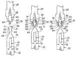
- FIGS. 4A-4C illustrate a buckle 30 that can be used to securely couple the drive leader 32 to the cartridge leader 28 .
- the second buckle component 56 includes a tab 58 integrally formed into a distal end of the drive leader 32
- the first buckle component 54 includes a receiver 60 integrally formed into a distal end of the cartridge leader 28 .
- FIGS. 4A-4C sequentially illustrate the tab 58 of the drive leader 32 being inserted and subsequently connected to the receiver 60 of the cartridge leader 28 . More specifically, FIG. 4A illustrates the buckle 30 in an uncoupled position, FIG. 4B illustrates the buckle 30 in an intermediate position and FIG. 4C illustrates the buckle 30 in a coupled position.
- the tab 58 inserts into the receiver 60 to couple the drive leader 32 to the cartridge leader 28 .
- the tab 58 includes a nose 62 and a neck 64 .
- the receiver 60 includes a rounded hoop portion 66 and a slot portion 68 .
- the nose 62 is dimensioned to fit through the hoop portion 66 but not the slot portion 68 .
- the neck 64 is dimensioned to fit in both the hoop portion 66 and the slot portion 68 . Stated another way, the hoop portion 66 of the receiver 60 is wide enough to receive the nose 62 and the neck 64 of the tab 58 and the slot portion 68 is wide enough to receive the neck 64 of the tab 58 but block the nose 62 .
- the nose 62 includes a pair of opposed proximal edges 69 that cantilever away from the neck 64 and engage the receiver 60 to couple the buckle components 54 , 56 .
- at least one, and more preferably both of the opposed proximal edges 69 are curved or arc shaped.
- the nose 62 defines a pair of opposed ears 71 that cantilever away from the neck 64 .
- This design reduces the likelihood of partly coupled leaders 28 , 32 and/or a half-ear situation in which only one of the ears 71 is positioned behind the slot portion 68 . Stated another way, with this design, the receiver 60 releases the tab 58 if only one of the opposed proximal edges 69 is engaging the slot portion 68 of the receiver 60 . This reduces the likelihood of a half-ear situation fooling the detector 33 and reduces the likelihood of leader runaway.
- the nose 62 also includes a distal end 74 .
- the distal end 74 is rounded or arc shaped to facilitate the movement of the nose 62 into the hoop portion 66 of the receiver 60 during the coupling process.
- the nose 62 has a rounded or oval profile.
- each ear 71 is semi-circular shaped.
- the tab and the receiver can be reversed for the buckle 30 .
- the tab could be formed as part of the cartridge leader 28 and the receiver can be formed as part of the drive leader 32 .
- the drive leader 32 also includes a buckler aperture 70 that is selectively retained by the buckler 31 .
- the buckler aperture 70 is sized and shaped to retain a portion of the buckler 31 during the coupling process and allow that portion of the buckler 31 to slide out when the coupling process is successfully completed as provided below.
- the buckler aperture 70 illustrated in FIGS. 4A-4C is somewhat rectangular shaped. However, a width 72 of the buckler aperture 70 gradually increases as the distance from the second buckle component 56 increases. Stated another way, a proximal portion 73 of the buckler aperture 70 is wider than a distal portion 75 of the buckler aperture 70 .
- the buckler 31 moves relative to the cartridge receiver 18 to couple and uncouple the buckle 30 . More specifically, the buckler 31 selectively retains and moves the drive leader 32 to couple the drive leader 32 to the cartridge leader 28 . Preferably, the buckler 31 retains the drive leader 32 until the detector 33 indicates that the cartridge leader 28 is securely coupled to the drive leader 32 . This feature allows the buckler 31 to move the drive leader 32 and make multiple attempts, if necessary, to couple the cartridge leader 28 to the drive leader 32 . Further, this allows the tape drive 10 to notify the operator to take appropriate corrective action prior to a “leader runaway” failure.
- the location and design of the buckler 31 can be varied to suit the design requirements of the tape drive 10 .
- the buckler 31 is positioned near the rear of the cartridge receiver 18 between the take-up reel 16 and the cartridge receiver 18
- FIG. 5 illustrates a perspective view of a suitable buckler 31 that can be used with the present invention.
- the buckler 31 includes a leader retainer 76 , a buckler shaft 77 , a tucker 78 , a buckler support 80 that mounts the buckler 31 to the drive housing 12 , and a buckler mover 82 .
- the leader retainer 76 selectively retains the drive leader 32 .
- the leader retainer 76 fits within the buckler aperture 70 to selectively retain and move the drive leader 32 .
- the leader retainer 76 includes (i) a tubular shaped retainer hub 84 that fits over and is rigidly secured to the buckler shaft 77 , (ii) a retainer beam 86 that cantilevers away from the retainer hub 84 and (iii) a catch 88 that extends transversely from a distal end of the retainer beam 86 .
- the catch 88 is dimensioned to fit through a portion of the buckler aperture 70 but not the entire buckler aperture 70 . More specifically, the catch 88 fits through the proximal portion 73 of buckler aperture 70 but not the distal portion 75 of the buckler aperture 70 .
- the retainer beam 86 is designed to fit in any portion of the buckler aperture 70 . Stated another way, the proximal portion 73 of the buckler aperture 70 is wide enough to receive the retainer beam 86 and the catch 88 and the distal portion 75 of the buckler aperture 70 is wide enough to receive the retainer beam 86 but block the catch 88 . With this design, the catch 88 keeps the buckler 31 engaged with the drive leader 32 until the detector 33 indicates that a successful coupling has occurred. Because the catch 88 does not fit through the distal portion 75 of the buckler aperture 70 , the leaders 28 , 32 can be moved robustly with the leader retainer 76 securely retaining the drive leader 32 .
- the tucker 78 supports the tab 58 of the second buckle component 56 and moves the tab 58 towards the cartridge leader 28 for coupling with the first buckle component 54 . More specifically, during coupling, the tucker 78 moves the tab 58 within the receiver 60 of the first buckle component 54 .
- the tucker 78 includes a tucker hub 90 , a tucker beam 92 , and a tucker spring (not shown).
- the tucker hub 90 loosely encircles the buckler shaft 77 below the retainer hub 84 and allows the tucker 78 to rotate, at least partly around the buckler shaft 77 .
- the tucker beam 92 cantilevers away from the tucker hub 90 .
- a distal end of the tucker beam 92 engages the tab 58 .
- the tucker spring encircles the buckler shaft 77 and is connected between the buckler support 80 and the tucker 78 .
- the tucker spring biases the tucker 78 to rotate in a clockwise direction. As the leader retainer 76 rotates clockwise, the tucker 78 follows the leader retainer 76 until the tucker 78 engages and contacts a stop (not shown) on the buckler support 80 .
- the buckler mover 82 moves the buckler 31 to couple and decouple the drive leader 32 to the cartridge leader 28 .
- the buckler mover 82 rotates the buckler shaft 77 and the leader retainer 76 .
- the design of the buckler mover 82 can be varied.
- the buckler mover 82 illustrated is a small, electric stepper motor.
- the buckling system 20 also includes a detector 33 that checks to determine if the cartridge leader 28 is securely coupled to the drive leader 32 . This feature allows the tape drive 10 to make multiple attempts, if necessary, to couple the drive leader 32 to the cartridge leader 28 .
- the detector 33 determines if the drive leader 32 is securely coupled to the cartridge leader 28 . This feature allows the tape drive 10 to make multiple attempts, if necessary, to couple the cartridge leader 28 to the drive leader 32 . Further, this allows the tape drive 10 to notify the operator to take appropriate corrective action prior to a “leader runaway” failure.
- the design and location of the detector 33 can be varied to suit the design requirements of the tape drive 10 .
- the detector 33 monitors and measures rotation of one of the tape guides 44 . More specifically, the detector 33 monitors rotation of the tape guide 44 closest to the take-up reel 16 to determine if buckling was successful. With this information, the detector 33 is able to determine if the leaders 28 , 32 are securely coupled.
- FIG. 6A illustrates a top perspective view
- FIG. 6B illustrates a side plan view of a detector 33 having features of the present invention.
- this type of detector 33 is commonly referred to as an encoder.
- the detector 33 includes a detector disk 94 and a sensor 96 .
- the detector disk 94 is secured to one of the tape guides 44 and rotates with one of the tape guides 44 .
- the detector disk 94 is secured to and rotates with the guide body 46 of the tape guide 44 closest to the take-up reel 16 .
- the detector disk 94 includes (i) an opaque disk body 98 and (ii) a plurality of spaced apart, radially oriented, transparent, windows 99 .
- the shape, number and spacing of the windows 99 in the detector disk 94 can be varied.
- a suitable detector disk 94 can include between approximately 180 and 360 spaced apart windows 99 .
- the windows 99 illustrated in FIG. 6A are provided to facilitate the discussion of the detector 33 .
- the sensor 96 measures and monitors the movement of the detector disk 94 . More specifically, the sensor 96 measures the amount of rotation of the detector disk 94 .
- the design of the sensor 96 can be varied. For example, in the embodiment illustrated in FIG. 6B, the sensor 96 includes a “C” shaped detector body 100 , an illumination source 102 and a sensor receiver 104 .
- the detector body 100 is secured to the drive housing 12 and maintains the illumination source 102 and the sensor receiver 104 on opposite sides of the detector disk 94 .
- the illumination source 102 directs a light beam at the detector disk 94 near the windows 99 at the sensor receiver 104 .
- the sensor receiver 104 detects light.
- the detector disk 94 rotates relative to the detector sensor 96 .
- the light from the illumination source 102 is directed towards the disk body 98 near the windows 99 .
- the light beam is either directed at one of the windows 99 or the disk body 98 between adjacent windows 99 .
- the windows 99 allow the light to pass to the sensor receiver 104 while the disk body 98 blocks the passage of light to the sensor receiver 104 .
- the sensor receiver 104 detects and counts the number of successive windows 99 that are moved into the path of the light beam. By counting the number of windows 99 that are successively positioned in the path of the light beam, the detector sensor 96 monitors the rotation of the detector disk 94 and one of the tape guides 44 .
- FIGS. 7A, 8 A and 9 illustrate a top view of a portion of the tape drive 10 and the cartridge 22 at alternate stages of coupling. More specifically, FIG. 7A illustrates the relative positions of the take-up reel 16 , the buckler 31 and the buckle 30 upon insertion of the cartridge 22 . FIG. 8A illustrates the relative positions of the take-up reel 16 , the buckler 31 and the buckle 30 during testing to determine if the buckling was successful. FIG. 9 illustrates the relative positions of the take-up reel 16 , the buckler 31 and the buckle 30 after successful buckling. A number of components of the tape drive 10 are omitted from FIGS. 7A, 8 A and 9 for clarity. FIGS. 7B and 8B are cut-away views of the leaders 28 , 32 .
- the cartridge 22 is inserted into the cartridge receiver 18 . Insertion of the cartridge 22 causes the cartridge door 52 to engage the protruding wall 53 and rotate to the open position.
- the tab 58 is positioned near the hoop portion 66 of the receiver 60 .
- the buckler 31 is in an uncoupled position. In this position, the buckler 31 retains the drive leader 32 so that the tab 58 is positioned near the hoop portion 66 of the receiver 60 when the cartridge 22 is inserted into the cartridge receiver 18 .
- the take-up motor 45 rotates the take-up reel 16 in the clockwise direction.
- the buckler mover 82 rotates the leader retainer 76 clockwise to the position illustrated in FIG. 8 A.
- the tucker 78 which is biased in the clockwise direction, tucks the nose 62 of the tab 58 into the hoop portion 66 of the receiver 60 .
- the buckle 30 is securely coupled.
- the detector 33 monitors the amount of rotation in the clockwise direction of the tape guide 44 closest to the take-up reel 16 .
- tape drive 10 tests to make sure that coupling was successful. More specifically, the cartridge reel motor 49 rotates the cartridge reel 24 in the counterclockwise direction. This pulls the cartridge leader 28 towards the cartridge 22 . If the two leaders 28 , 32 are securely coupled, the drive leader 32 will move towards the cartridge 22 and the detector 33 will detect and measure counterclockwise rotation of the tape guide 44 closest to the take-up reel 16 . If the detector 33 does not sense the rotation in the counterclockwise direction, the two leaders 28 , 32 were not successfully coupled.
- the buckler 31 is in a test position during the test to make sure that coupling was successful. More specifically, the leader retainer 76 is still positioned within the distal portion 75 of the buckler aperture 70 during testing of the adequacy of the coupling process. With this design, the leader retainer 76 is maintained within the buckler aperture 70 until the detector 33 determines that the buckling process was successful. This prevents leader runaway.
- the leader retainer 76 will be rotated counterclockwise by the buckler mover 82 to the uncoupled position illustrated in FIG. 7 A and the coupling operation can be repeated. After a set number of unsuccessful attempts at coupling, the tape drive 10 can indicate to an operator that the cartridge 22 may be defective.
- the leader retainer 76 is further rotated in the clockwise direction by the buckler mover 82 so that the catch 88 slides out of the proximal portion 73 of the buckler aperture 70 in the drive leader 32 . Subsequently, the buckler mover 82 rotates the leader retainer 76 away from the tape path as illustrated in FIG. 9 . After the leaders 28 , 32 are coupled, rotation of the take-up reel 16 results in movement of the storage tape 26 from the cartridge reel 24 past the data transducer 14 to the take-up reel 16 .
- At least one, and more preferably both of the opposed proximal edges 69 are curved or arc shaped.
- the nose 62 slides out of the slot portion 68 of the receiver 60 unless both of the proximal edges 69 are securely tucked within the slot portion 68 .
- This design reduces the likelihood of partly coupled leaders 28 , 32 and/or a half-ear situation in which only one of the ears 71 is positioned behind the slot portion 68 .
- the receiver 60 releases the tab 58 if only one of opposed proximal edges 69 is engaging the slot portion 68 of the receiver 60 . This reduces the likelihood of a half-ear situation fooling the detector 33 .
- the storage tape 26 is wound back onto the cartridge reel 24 .
- the buckle 30 will be right in front of the buckler 31 .
- the leader retainer 76 is rotated counter-clockwise by the buckler mover 82 so that the catch 88 and the retainer beam 86 slides through the proximal portion 73 of the buckler aperture 70 . Additional rotation of the leader retainer 76 moves the retainer beam 86 into the distal portion 75 of the buckler aperture 70 . Further rotation of the leader retainer 76 results in the leader retainer 76 moving the drive leader 32 to the unbuckle position and the tab 58 being moved into the hoop portion 66 of the receiver 60 .
Landscapes
- Replacement Of Web Rolls (AREA)
Abstract
Description
Claims (20)
Priority Applications (1)
| Application Number | Priority Date | Filing Date | Title |
|---|---|---|---|
| US09/515,463 US6588694B1 (en) | 2000-02-29 | 2000-02-29 | Take-up reel leader for DLT tape drive |
Applications Claiming Priority (1)
| Application Number | Priority Date | Filing Date | Title |
|---|---|---|---|
| US09/515,463 US6588694B1 (en) | 2000-02-29 | 2000-02-29 | Take-up reel leader for DLT tape drive |
Publications (1)
| Publication Number | Publication Date |
|---|---|
| US6588694B1 true US6588694B1 (en) | 2003-07-08 |
Family
ID=24051450
Family Applications (1)
| Application Number | Title | Priority Date | Filing Date |
|---|---|---|---|
| US09/515,463 Expired - Fee Related US6588694B1 (en) | 2000-02-29 | 2000-02-29 | Take-up reel leader for DLT tape drive |
Country Status (1)
| Country | Link |
|---|---|
| US (1) | US6588694B1 (en) |
Cited By (7)
| Publication number | Priority date | Publication date | Assignee | Title |
|---|---|---|---|---|
| US20030122015A1 (en) * | 2001-12-28 | 2003-07-03 | Fuji Photo Film Co., Ltd. | Recording tape cartridge |
| US20050082407A1 (en) * | 2003-10-20 | 2005-04-21 | Saliba George A. | Multiple format magnetic storage media drive |
| US7172149B1 (en) * | 2005-08-22 | 2007-02-06 | Tandberg Storage Asa | Long tape path guide system and method |
| US20070170294A1 (en) * | 2006-01-20 | 2007-07-26 | Quantum Corporation | Cartridge buckle reinforcement and damage indicator |
| US7913943B1 (en) * | 2005-11-10 | 2011-03-29 | Oracle America, Inc. | Tape drive |
| US11017810B2 (en) * | 2013-12-16 | 2021-05-25 | International Business Machines Corporation | Spring clip leader and housing for magnetic tape |
| US11676635B1 (en) * | 2021-06-23 | 2023-06-13 | Quantum Corporation | Large form factor extended tape path magnetic tape storage device |
Citations (16)
| Publication number | Priority date | Publication date | Assignee | Title |
|---|---|---|---|---|
| US1655297A (en) * | 1925-12-01 | 1928-01-03 | Thornton John Edward | Motion-picture-projecting machine |
| GB716632A (en) | 1951-01-02 | 1954-10-13 | Loewe Opta Ag | Magnetic recording and reproducing device |
| GB1167445A (en) | 1967-01-23 | 1969-10-15 | Grundig Emv | Improvements in or relating to Devices for Signal Recording and Playback Equipment |
| US3706423A (en) * | 1971-01-04 | 1972-12-19 | Bell & Howell Co | Automatic loading and unloading tape transport apparatus utilizing a captive leader |
| US3724776A (en) * | 1971-02-09 | 1973-04-03 | Eastman Kodak Co | Film feeding apparatus |
| US3880382A (en) * | 1972-10-26 | 1975-04-29 | Int Video Corp | Tape extractor for magnetic tape cartridge system |
| US4572460A (en) * | 1984-02-13 | 1986-02-25 | Digital Equipment Corporation | Means for pulling tape from a reel |
| US4662049A (en) | 1984-02-13 | 1987-05-05 | Digital Equipment Corporation | Mechanism for joining tape leaders |
| US4720913A (en) | 1984-02-13 | 1988-01-26 | Digital Equipment Corporation | Mechanism for joining tape leaders |
| US5542620A (en) | 1990-07-18 | 1996-08-06 | Fujitsu Limited | Tape threading apparatus used in a tape unit |
| US5769346A (en) * | 1996-06-19 | 1998-06-23 | Quantum Corporation | Tape buckling mechanism for single reel cartridge tape recording |
| US6092754A (en) * | 1998-09-08 | 2000-07-25 | Quantum Corporation | Buckler for a tape drive |
| US6095445A (en) * | 1998-09-02 | 2000-08-01 | Quantum Corporation | Cartridge buckler for a tape drive |
| US6186430B1 (en) * | 1999-04-16 | 2001-02-13 | Benchmark Tape Systems Corporation | Tape drive connection sensing assembly |
| US6227475B1 (en) * | 1998-07-23 | 2001-05-08 | Hewlett-Packard Co. | Tape threading apparatus |
| US6257514B1 (en) * | 1999-06-25 | 2001-07-10 | Benchmark Tape Systems Corporation | Guiding assembly for protecting a magnetic tape head |
-
2000
- 2000-02-29 US US09/515,463 patent/US6588694B1/en not_active Expired - Fee Related
Patent Citations (16)
| Publication number | Priority date | Publication date | Assignee | Title |
|---|---|---|---|---|
| US1655297A (en) * | 1925-12-01 | 1928-01-03 | Thornton John Edward | Motion-picture-projecting machine |
| GB716632A (en) | 1951-01-02 | 1954-10-13 | Loewe Opta Ag | Magnetic recording and reproducing device |
| GB1167445A (en) | 1967-01-23 | 1969-10-15 | Grundig Emv | Improvements in or relating to Devices for Signal Recording and Playback Equipment |
| US3706423A (en) * | 1971-01-04 | 1972-12-19 | Bell & Howell Co | Automatic loading and unloading tape transport apparatus utilizing a captive leader |
| US3724776A (en) * | 1971-02-09 | 1973-04-03 | Eastman Kodak Co | Film feeding apparatus |
| US3880382A (en) * | 1972-10-26 | 1975-04-29 | Int Video Corp | Tape extractor for magnetic tape cartridge system |
| US4720913A (en) | 1984-02-13 | 1988-01-26 | Digital Equipment Corporation | Mechanism for joining tape leaders |
| US4662049A (en) | 1984-02-13 | 1987-05-05 | Digital Equipment Corporation | Mechanism for joining tape leaders |
| US4572460A (en) * | 1984-02-13 | 1986-02-25 | Digital Equipment Corporation | Means for pulling tape from a reel |
| US5542620A (en) | 1990-07-18 | 1996-08-06 | Fujitsu Limited | Tape threading apparatus used in a tape unit |
| US5769346A (en) * | 1996-06-19 | 1998-06-23 | Quantum Corporation | Tape buckling mechanism for single reel cartridge tape recording |
| US6227475B1 (en) * | 1998-07-23 | 2001-05-08 | Hewlett-Packard Co. | Tape threading apparatus |
| US6095445A (en) * | 1998-09-02 | 2000-08-01 | Quantum Corporation | Cartridge buckler for a tape drive |
| US6092754A (en) * | 1998-09-08 | 2000-07-25 | Quantum Corporation | Buckler for a tape drive |
| US6186430B1 (en) * | 1999-04-16 | 2001-02-13 | Benchmark Tape Systems Corporation | Tape drive connection sensing assembly |
| US6257514B1 (en) * | 1999-06-25 | 2001-07-10 | Benchmark Tape Systems Corporation | Guiding assembly for protecting a magnetic tape head |
Cited By (12)
| Publication number | Priority date | Publication date | Assignee | Title |
|---|---|---|---|---|
| US20030122015A1 (en) * | 2001-12-28 | 2003-07-03 | Fuji Photo Film Co., Ltd. | Recording tape cartridge |
| US6926220B2 (en) * | 2001-12-28 | 2005-08-09 | Fuji Photo Film Co., Ltd. | Recording tape cartridge |
| US20050082407A1 (en) * | 2003-10-20 | 2005-04-21 | Saliba George A. | Multiple format magnetic storage media drive |
| US7099102B2 (en) | 2003-10-20 | 2006-08-29 | Quantum Corporation | Multiple format magnetic storage media drive |
| US7172149B1 (en) * | 2005-08-22 | 2007-02-06 | Tandberg Storage Asa | Long tape path guide system and method |
| US7913943B1 (en) * | 2005-11-10 | 2011-03-29 | Oracle America, Inc. | Tape drive |
| US20110139917A1 (en) * | 2005-11-10 | 2011-06-16 | Oracle America, Inc. | Tape drive |
| US8220734B2 (en) | 2005-11-10 | 2012-07-17 | Oracle America, Inc. | Tape drive |
| US20070170294A1 (en) * | 2006-01-20 | 2007-07-26 | Quantum Corporation | Cartridge buckle reinforcement and damage indicator |
| US7484681B2 (en) | 2006-01-20 | 2009-02-03 | Quantum Corporation | Cartridge buckle reinforcement and damage indicator |
| US11017810B2 (en) * | 2013-12-16 | 2021-05-25 | International Business Machines Corporation | Spring clip leader and housing for magnetic tape |
| US11676635B1 (en) * | 2021-06-23 | 2023-06-13 | Quantum Corporation | Large form factor extended tape path magnetic tape storage device |
Similar Documents
| Publication | Publication Date | Title |
|---|---|---|
| US5971310A (en) | Positive engagement buckle for a tape drive and cartridge | |
| US5547142A (en) | Tape cassette with internal tape cleaning and locking | |
| US4262860A (en) | Tape cartridge with increased tape capacity | |
| US6034850A (en) | Two-part tape cartridge reel locking mechanism | |
| JPH0559676U (en) | Video tape cartridge | |
| JPH11149750A (en) | Tape cartridge | |
| US6344944B2 (en) | Mini-cartridge adapter for adapting a mini-cartridge to an industry standard tape cartridge format | |
| US6364232B1 (en) | Recording and/or reproducing device having a take-up reel and having a tape pull-out assembly which can be positioned tangentially with respect to the take-up reel | |
| US6588694B1 (en) | Take-up reel leader for DLT tape drive | |
| US6311915B1 (en) | Buckler for a tape drive | |
| US6092754A (en) | Buckler for a tape drive | |
| EP0409534A2 (en) | Carrier with tape connector interlock for videocassette | |
| US6550710B2 (en) | Tape cartridge leader for single reel tape cartridges having increased flexibility for improved performance | |
| EP1191534B1 (en) | Drive leader and take-up reel for a tape drive | |
| US6330983B1 (en) | Recording and/or reproducing device having a tape pull-out element and a coupling element and having guide means for these two parts | |
| JPH08511123A (en) | Mechanically non-compliant magnetic recording tape cartridge with identical type elements | |
| US6964391B2 (en) | Recording tape cartridge | |
| US20030227715A1 (en) | Head shield for a tape drive | |
| EP0450976A2 (en) | Tape cassette | |
| JP2003123433A (en) | Recording tape cartridge | |
| US6375108B1 (en) | Multi-layered drive leader for a tape drive | |
| US6267325B1 (en) | Tape support | |
| US20080135663A1 (en) | Tape leader buckler having increased hooking area | |
| JP3723763B2 (en) | Recording tape cartridge | |
| US6915975B2 (en) | Tape leader means for pulling tape from a reel |
Legal Events
| Date | Code | Title | Description |
|---|---|---|---|
| AS | Assignment |
Owner name: QUANTUM CORPORATION, CALIFORNIA Free format text: ASSIGNMENT OF ASSIGNORS INTEREST;ASSIGNOR:WILKERSON, DALE A.;REEL/FRAME:010677/0419 Effective date: 20000222 |
|
| AS | Assignment |
Owner name: KEYBANK NATIONAL ASSOCIATION, IDAHO Free format text: SECURITY AGREEMENT;ASSIGNOR:QUANTUM CORP.;REEL/FRAME:013616/0759 Effective date: 20021217 |
|
| AS | Assignment |
Owner name: KEYBANK NATIONAL ASSOCIATION, AS ADMINISTRATIVE AGENT, CALIFORNIA Free format text: INTELLECTUAL PROPERTY SECURITY AGREEMENT (SECOND LIEN);ASSIGNOR:QUANTUM CORPORATION;REEL/FRAME:018268/0475 Effective date: 20060822 Owner name: KEYBANK NATIONAL ASSOCIATION, AS ADMINISTRATIVE AG Free format text: INTELLECTUAL PROPERTY SECURITY AGREEMENT (SECOND LIEN);ASSIGNOR:QUANTUM CORPORATION;REEL/FRAME:018268/0475 Effective date: 20060822 |
|
| AS | Assignment |
Owner name: KEYBANK NATIONAL ASSOCIATION, AS ADMINISTRATIVE AGENT, WASHINGTON Free format text: INTELLECTUAL PROPERTY SECURITY AGREEMENT (FIRST LIEN);ASSIGNOR:QUANTUM CORPORATION;REEL/FRAME:018303/0282 Effective date: 20060822 Owner name: KEYBANK NATIONAL ASSOCIATION, AS ADMINISTRATIVE AG Free format text: INTELLECTUAL PROPERTY SECURITY AGREEMENT (FIRST LIEN);ASSIGNOR:QUANTUM CORPORATION;REEL/FRAME:018303/0282 Effective date: 20060822 |
|
| FPAY | Fee payment |
Year of fee payment: 4 |
|
| AS | Assignment |
Owner name: QUANTUM CORPORATION, CALIFORNIA Free format text: TERMINATION OF SECURITY INTEREST IN PATENTS REEL 018269 FRAME 0005 AND REEL 018268 FRAME 0475;ASSIGNOR:KEY BANK, NATIONAL ASSOCIATION;REEL/FRAME:019550/0659 Effective date: 20070712 Owner name: QUANTUM CORPORATION,CALIFORNIA Free format text: TERMINATION OF SECURITY INTEREST IN PATENTS REEL 018269 FRAME 0005 AND REEL 018268 FRAME 0475;ASSIGNOR:KEY BANK, NATIONAL ASSOCIATION;REEL/FRAME:019550/0659 Effective date: 20070712 |
|
| AS | Assignment |
Owner name: QUANTUM CORPORATION, CALIFORNIA Free format text: RELEASE OF INTELLECTUAL PROPERTY SECURITY AGREEMENT AT REEL 018303 FRAME 0282;ASSIGNOR:KEYBANK NATIONAL ASSOCIATION;REEL/FRAME:019573/0001 Effective date: 20070712 |
|
| AS | Assignment |
Owner name: CREDIT SUISSE, NEW YORK Free format text: SECURITY AGREEMENT;ASSIGNORS:QUANTUM CORPORATION;ADVANCED DIGITAL INFORMATION CORPORATION;CERTANCE HOLDINGS CORPORATION;AND OTHERS;REEL/FRAME:019605/0159 Effective date: 20070712 Owner name: CREDIT SUISSE,NEW YORK Free format text: SECURITY AGREEMENT;ASSIGNORS:QUANTUM CORPORATION;ADVANCED DIGITAL INFORMATION CORPORATION;CERTANCE HOLDINGS CORPORATION;AND OTHERS;REEL/FRAME:019605/0159 Effective date: 20070712 |
|
| FPAY | Fee payment |
Year of fee payment: 8 |
|
| AS | Assignment |
Owner name: QUANTUM CORPORATION, CALIFORNIA Free format text: RELEASE OF SECURITY INTEREST IN PATENT COLLATERAL RECORDED AT REEL/FRAME NO 013616/0759;ASSIGNOR:KEYBANK NATIONAL ASSOCIATION;REEL/FRAME:027941/0352 Effective date: 20120327 |
|
| AS | Assignment |
Owner name: ADVANCED DIGITAL INFORMATION CORPORATION, WASHINGTON Free format text: RELEASE BY SECURED PARTY;ASSIGNOR:CREDIT SUISSE, CAYMAN ISLANDS BRANCH (FORMERLY KNOWN AS CREDIT SUISSE), AS COLLATERAL AGENT;REEL/FRAME:027968/0007 Effective date: 20120329 Owner name: WELLS FARGO CAPITAL FINANCE, LLC, AS AGENT, CALIFORNIA Free format text: SECURITY AGREEMENT;ASSIGNOR:QUANTUM CORPORATION;REEL/FRAME:027967/0914 Effective date: 20120329 Owner name: CERTANCE HOLDINGS CORPORATION, WASHINGTON Free format text: RELEASE BY SECURED PARTY;ASSIGNOR:CREDIT SUISSE, CAYMAN ISLANDS BRANCH (FORMERLY KNOWN AS CREDIT SUISSE), AS COLLATERAL AGENT;REEL/FRAME:027968/0007 Effective date: 20120329 Owner name: ADVANCED DIGITAL INFORMATION CORPORATION, WASHINGT Free format text: RELEASE BY SECURED PARTY;ASSIGNOR:CREDIT SUISSE, CAYMAN ISLANDS BRANCH (FORMERLY KNOWN AS CREDIT SUISSE), AS COLLATERAL AGENT;REEL/FRAME:027968/0007 Effective date: 20120329 Owner name: QUANTUM INTERNATIONAL, INC., WASHINGTON Free format text: RELEASE BY SECURED PARTY;ASSIGNOR:CREDIT SUISSE, CAYMAN ISLANDS BRANCH (FORMERLY KNOWN AS CREDIT SUISSE), AS COLLATERAL AGENT;REEL/FRAME:027968/0007 Effective date: 20120329 Owner name: CERTANCE, LLC, WASHINGTON Free format text: RELEASE BY SECURED PARTY;ASSIGNOR:CREDIT SUISSE, CAYMAN ISLANDS BRANCH (FORMERLY KNOWN AS CREDIT SUISSE), AS COLLATERAL AGENT;REEL/FRAME:027968/0007 Effective date: 20120329 Owner name: WELLS FARGO CAPITAL FINANCE, LLC, AS AGENT, CALIFO Free format text: SECURITY AGREEMENT;ASSIGNOR:QUANTUM CORPORATION;REEL/FRAME:027967/0914 Effective date: 20120329 Owner name: CERTANCE (US) HOLDINGS, INC., WASHINGTON Free format text: RELEASE BY SECURED PARTY;ASSIGNOR:CREDIT SUISSE, CAYMAN ISLANDS BRANCH (FORMERLY KNOWN AS CREDIT SUISSE), AS COLLATERAL AGENT;REEL/FRAME:027968/0007 Effective date: 20120329 Owner name: QUANTUM CORPORATION, WASHINGTON Free format text: RELEASE BY SECURED PARTY;ASSIGNOR:CREDIT SUISSE, CAYMAN ISLANDS BRANCH (FORMERLY KNOWN AS CREDIT SUISSE), AS COLLATERAL AGENT;REEL/FRAME:027968/0007 Effective date: 20120329 |
|
| REMI | Maintenance fee reminder mailed | ||
| LAPS | Lapse for failure to pay maintenance fees | ||
| STCH | Information on status: patent discontinuation |
Free format text: PATENT EXPIRED DUE TO NONPAYMENT OF MAINTENANCE FEES UNDER 37 CFR 1.362 |
|
| FP | Lapsed due to failure to pay maintenance fee |
Effective date: 20150708 |
|
| AS | Assignment |
Owner name: QUANTUM CORPORATION, CALIFORNIA Free format text: RELEASE BY SECURED PARTY;ASSIGNOR:WELLS FARGO CAPITAL FINANCE, LLC, AS AGENT;REEL/FRAME:040474/0079 Effective date: 20161021 |