US658757A - Band sawing-machine. - Google Patents
Band sawing-machine. Download PDFInfo
- Publication number
- US658757A US658757A US1899715164A US658757A US 658757 A US658757 A US 658757A US 1899715164 A US1899715164 A US 1899715164A US 658757 A US658757 A US 658757A
- Authority
- US
- United States
- Prior art keywords
- band
- saw
- roll
- feeding
- slide
- Prior art date
- Legal status (The legal status is an assumption and is not a legal conclusion. Google has not performed a legal analysis and makes no representation as to the accuracy of the status listed.)
- Expired - Lifetime
Links
Images


Classifications
-
- B—PERFORMING OPERATIONS; TRANSPORTING
- B26—HAND CUTTING TOOLS; CUTTING; SEVERING
- B26D—CUTTING; DETAILS COMMON TO MACHINES FOR PERFORATING, PUNCHING, CUTTING-OUT, STAMPING-OUT OR SEVERING
- B26D1/00—Cutting through work characterised by the nature or movement of the cutting member or particular materials not otherwise provided for; Apparatus or machines therefor; Cutting members therefor
- B26D1/01—Cutting through work characterised by the nature or movement of the cutting member or particular materials not otherwise provided for; Apparatus or machines therefor; Cutting members therefor involving a cutting member which does not travel with the work
- B26D1/12—Cutting through work characterised by the nature or movement of the cutting member or particular materials not otherwise provided for; Apparatus or machines therefor; Cutting members therefor involving a cutting member which does not travel with the work having a cutting member moving about an axis
- B26D1/25—Cutting through work characterised by the nature or movement of the cutting member or particular materials not otherwise provided for; Apparatus or machines therefor; Cutting members therefor involving a cutting member which does not travel with the work having a cutting member moving about an axis with a non-circular cutting member
- B26D1/34—Cutting through work characterised by the nature or movement of the cutting member or particular materials not otherwise provided for; Apparatus or machines therefor; Cutting members therefor involving a cutting member which does not travel with the work having a cutting member moving about an axis with a non-circular cutting member moving about an axis parallel to the line of cut
- B26D1/38—Cutting through work characterised by the nature or movement of the cutting member or particular materials not otherwise provided for; Apparatus or machines therefor; Cutting members therefor involving a cutting member which does not travel with the work having a cutting member moving about an axis with a non-circular cutting member moving about an axis parallel to the line of cut and coacting with a fixed blade or other fixed member
- B26D1/385—Cutting through work characterised by the nature or movement of the cutting member or particular materials not otherwise provided for; Apparatus or machines therefor; Cutting members therefor involving a cutting member which does not travel with the work having a cutting member moving about an axis with a non-circular cutting member moving about an axis parallel to the line of cut and coacting with a fixed blade or other fixed member for thin material, e.g. for sheets, strips or the like
-
- Y—GENERAL TAGGING OF NEW TECHNOLOGICAL DEVELOPMENTS; GENERAL TAGGING OF CROSS-SECTIONAL TECHNOLOGIES SPANNING OVER SEVERAL SECTIONS OF THE IPC; TECHNICAL SUBJECTS COVERED BY FORMER USPC CROSS-REFERENCE ART COLLECTIONS [XRACs] AND DIGESTS
- Y10—TECHNICAL SUBJECTS COVERED BY FORMER USPC
- Y10T—TECHNICAL SUBJECTS COVERED BY FORMER US CLASSIFICATION
- Y10T83/00—Cutting
- Y10T83/202—With product handling means
- Y10T83/2074—Including means to divert one portion of product from another
- Y10T83/2077—By kerf entering guide
-
- Y—GENERAL TAGGING OF NEW TECHNOLOGICAL DEVELOPMENTS; GENERAL TAGGING OF CROSS-SECTIONAL TECHNOLOGIES SPANNING OVER SEVERAL SECTIONS OF THE IPC; TECHNICAL SUBJECTS COVERED BY FORMER USPC CROSS-REFERENCE ART COLLECTIONS [XRACs] AND DIGESTS
- Y10—TECHNICAL SUBJECTS COVERED BY FORMER USPC
- Y10T—TECHNICAL SUBJECTS COVERED BY FORMER US CLASSIFICATION
- Y10T83/00—Cutting
- Y10T83/202—With product handling means
- Y10T83/2092—Means to move, guide, or permit free fall or flight of product
- Y10T83/2196—Roller[s]
-
- Y—GENERAL TAGGING OF NEW TECHNOLOGICAL DEVELOPMENTS; GENERAL TAGGING OF CROSS-SECTIONAL TECHNOLOGIES SPANNING OVER SEVERAL SECTIONS OF THE IPC; TECHNICAL SUBJECTS COVERED BY FORMER USPC CROSS-REFERENCE ART COLLECTIONS [XRACs] AND DIGESTS
- Y10—TECHNICAL SUBJECTS COVERED BY FORMER USPC
- Y10T—TECHNICAL SUBJECTS COVERED BY FORMER US CLASSIFICATION
- Y10T83/00—Cutting
- Y10T83/647—With means to convey work relative to tool station
- Y10T83/6579—With means to press work to work-carrier
-
- Y—GENERAL TAGGING OF NEW TECHNOLOGICAL DEVELOPMENTS; GENERAL TAGGING OF CROSS-SECTIONAL TECHNOLOGIES SPANNING OVER SEVERAL SECTIONS OF THE IPC; TECHNICAL SUBJECTS COVERED BY FORMER USPC CROSS-REFERENCE ART COLLECTIONS [XRACs] AND DIGESTS
- Y10—TECHNICAL SUBJECTS COVERED BY FORMER USPC
- Y10T—TECHNICAL SUBJECTS COVERED BY FORMER US CLASSIFICATION
- Y10T83/00—Cutting
- Y10T83/707—By endless band or chain knife
- Y10T83/7226—With means to guard the tension
- Y10T83/7239—With means to vary distance between pulley or sprocket axes
- Y10T83/7251—Including means to yieldably bias pulley
Definitions
- My invention relates to band sawing-malowering the feeding devices and setting mechanism for the latter; in so mounting the feeding mechanism and saw-guide for the band-saw blade that they act in unison in accommodating themselves to the varying thicknesses of the stock, and, further, in the parts and in the construction, arrangement, and combinations of parts hereinafter shown and described,
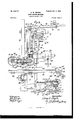
- Figure l is a side elevation of my improved device,and Fig. 2 afront elevalion thereof.
- Fig. 3 is a plan view of the upper saw-wheel mounting and connected parts.
- Fig. 4 is a rear elevation of the same.
- Fig. 5 is a plan view of the knife-bar for the sawwheel bearing and its side adjustments.
- Fig. 6 is a vertical cross-section of the feeding-out roll, and
- Fig. 7 a detailof the feeding-roll connectionsin side elevation.
- Fig. Sis a plan view of the feed-roll and saw-guide mechanisms, showing the primary slide in section on the line 8 8, Fig. 2.
- Fig. 9 is a plan view of my' machine with the upper part of the column,
- A represents the frame of the machine, and B B the upper and lower band-saw wheels, respectively, the wheel B being mounted in thefrax suitable mannerand being preferably a solid wheel, as shown in Fig. 1, to provide the necessary weight and to prevent the objectionable scattering of the sawdust common when a lower spoke-wheel is used caused by the air-currents produced by the spokes.
- Aband-saw blade 0 is propelled about the wheels.
- the wheel B is preferably mounted on a bracket, preferably adjustable vertically of the frame of the machine in the-following manner: Ways 1 are provided, on which the bracket is given its adjustment by means of a screw-shaft 2, journaled in a bearing 3 on the frame and taking through a lug 4 on the bracket.
- a collar 5 is secured to the screwshaft to retain it in place.
- a disk 6 has apertures or notches 7, into which a finger 8on a lever 9 may take.
- the lever is pivoted on a pivot 10 on a strap 11, which takes over the shaft and is revolubly secured thereto.
- a fixed collar 12 on the shaft holds the disk and lever collar in place.
- the lever is preferably forked at its pivoted end, the forks taking about the collars having sufficient clearance forthat purpose. Its outer end extends, preferably, beyond the periphery of the sawwheel.
- the lever is raised to bringits finger out of contactwith the notch on the disk and turned sidewise to bring the finger into contact with another suitable notch, when it is drawn sidewise to turn thescrew and again advanced to anothernotch, as may be necessary for the adjustment.
- the lever is allowed to remain in position after adjustment without danger of its being jarred out of position or into contact with the spokes .of the wheel and isat all timesready for additional adjustment; Adjustment of the bracket gives the saw-blade its proper tension.
- the saw-wheel is secured to an axle E, journaled in a hearing or bearings on a lever 16, fulcrumed on a bar 17, extending parallel to the axis of the wheel and supported near one end on a bolt 18, which may take through a threaded lug 19 on the bracket D and secured in place my means of a set-nut 20.
- a screw-shaft 21 is journaled in lugs 22 on the bracket and takes through a threaded aperture in the bar.
- the screw-shaft is secured against endwise movement by means of collars 23 24. It may have a squared end to receive a suitable wrench.
- This shaft may form the pivotal support for the angling vertical adjustment of the bar, and also serves to give the bar its sidewise adjustment at the end through which it takes.
- suitable bolts 25 may take through threaded apertures in lugs 27 on the bracket against the respective sides of the bar for the purpose of giving the bar its sidewise adjustment at that end.
- the bolt 18 gives to the bar a delicate vertical angling adjustment for horizontal alinement of the saw-wheel shaft, and the screw-shaft and setbolts give it a delicate sidewise adjustment.
- the bar 17 is provided with a knife-edge 28, on which the lever 16 is fulcrumed, as in the depression 29 thereon.
- a plate 30 is bolted to the bracket in suitable position and carries a lug 31, having a knife-edge 32, to which a pressure-lever 33, which may carry a suitable weight 34, is fulcrumed in a depression 35.
- the saw-wheel lever and the pressure-lever may also be provided, respectively, with depressions 36 37, into which the knife-edges 38 39 of a link 40 may take, connecting the two levers.
- a lug 41 may be secured to the plate to limit the depression of the pressure-lever.
- the bar 17 may also be provided with a plate 42, secured thereto by a bolt 43, and having a finger 44, taking over the lever 16 above its fulcrumed point, to retain the lever on its fulcrum in case of jar, as in the accidental breaking of the band-saw blade or from other causes.
- a finger 45 is secured to the bracket and has a rib on its under side which takes into a groove 46 in the saw-wheel lever or bearing to prevent endwise displacement of the latter. The upper saw-wheel and its adjustments and the pressure arrangements are all of them carried by the bracket.
- Motion is imparted to the lower saw-wheel in any suitable manner, which imparts motion to the saw-blade which encircles both wheels and communicates it to the upper saw-wheel.
- I provide a mandrel 47 for the lower saw-wheel, supporting tight and loose pulleys 48 and 49. (See Fig. 9.)
- a shaft 51 is journaled in a sleeve 52, secured to the frame of the machine, and carries a series of pulleys 53,which .2 was? may be operated from the shaft of the lower wheel bya series of similar pulleys attached thereto in any suitable way and operatingin the well-known manner of cone-pulleys. This latter series of pulleys I have designated 50.
- the shaft 51 also carries a worm 54, meshing with the worm-wheel 55 on a shaft 56, mounted in a bearing 57 in the frame of the machine.
- the worm-wheel 55 has a lubricator-reservoir 58, taking about the same for the purpose of feeding the worm-wheel and worm with the requisite amount of lubricator to insure easy operation and prevent wear of the parts.
- the shaft 56 communicates with an extensible shaft 59 by means of knuckle-joint 60.
- the extensible shaft consists, preferably, of the sleeve part 61 and the insert-ible part 62, telescoping therein and insured against revolving relatively thereto by means of splines and groove.
- a slide 65 which I shall call a primary slide, preferably slides in ways 66 in the bracket D, slidingly secured therein by suitable gibs.
- a slide 68 which I shall term a secondary slide, slides on the primary slide in ways 69, slidingly secured or dovetailed thereto in any suitable manner.
- the primary slide has a feeding-in roll 70, mounted therein on a horizontal shaft 71 in a bearing 72, the shaft 71 being secured to the shaft 59 by a knuckle-joint 73.
- the primary slide is preferably made with an extension 74, which may be pivoted to the slide, as by a pivot 75, so as to allow the extension to be raised out of range of the saw-blade for the ready removal of the latter and to accommodate itself to the varying thicknesses of stock.
- the extension may have a heel 76, adapted to strike a rubber or other cushion 77, secured in a socket 78, in which it may be given adjustment by a set-bolt 79.
- a feeding-out roll is mounted on a horizontal shaft 81, journaled in a bearing 2 in the extension 74. The feeding-rolls thus have horizontal axes, which they maintain throughout their adjustments.
- the shafts 71 and 81 carry sprocket-wheels 83 84, connected by a chain 85 and forming a driving mechanism for the feeding-out roll.
- the secondary slide 68 is preferably divided, forming an adjustable arm 68 guided on a rib 48 and secured in place by a bolt 49, passing through a slot into the slide proper.
- a suitable saw-guide 86 for the band-saw blade is secured on ways 63 on the adjustable arm of the secondary slide in any suitable manner, as by means of a set-screw 64, and is adjustable thereon to and away from the rear of the saw-blade in a line parallel to the sides of the latter and adjustable vertically with the secondary slide.
- a bolt 88 serves to secure the two slides together.
- the secondary slide is also adjustable with relation to the primary slide.
- the saw-guide thus has adjustments
- the band-saw guide 86 is provided at its forward end with guiding-blocks 103, which take against the band-saw blade adjacentto its tooth edge to both sides thereof, leaving the rear part of the band-saw blade free to guide the bandsaw blade in its cutting.
- a second saw-guide 89 may also be provided for the guidance of the blade after it passes the surface of the table 90 on which the stock is placed and over which it is fed when operated upon.
- Suitable rolls 91 92 may be placed in the table opposite the feed-rolls 7 0 and 80.
- the rolls 91 and 92 are preferably placed in juxtaposition to the band-saw blade position.
- the table and the rolls therein preferably act as suitable work-supporting agencies.
- the table has a slot 90 to allow the saw-blade to be inserted, the roll 92 being divided at the slot to permit the blade to pass to proper position about the wheels.
- the front or feedingin roll 70 is preferably provided with sharp teeth, that may bite into the wood and give a powerful feed, the marks being in the line of travel of the saw and obliterated by it when the cut is taken.
- the feeding-out roll may be of sufficient breadth to span the kerf of the blade and actuate both sides of the severed piece of stock.
- a guiding or parting tongue or disk or spreader 93 may have a guiding or parting tongue or disk or spreader 93, preferably intermediate of its ends and rotating with it to take into the kerf or cut of the saw-blade, and thereby guide the board, and may also relieve the blade of frictional contact with the sides of the stock through which it has just passed, forming an easily-operating and practically-frictionless feed, the guiding-tongue itself being a revolving moving agency in the feed.
- the guiding-tongue also serves as a guide when edging stock-that is, providing stock with a straight edge by which it can be fed against a side gage.
- the tongue takes into the saw-kerf and guides the board.
- the band-saw guide located between the feeding-in and the feeding-out roll acts on the band-saw blade near its tooth edge and guides the band-saw blade in its cutting.
- the contact of the saw-kerf in the board with the rear part of the band-saw blade will cause the tooth edge of the band-saw blade to swing back into its proper track, with the vertical plane of the contact between the band-saw blade and the band-saw guide acting as a pivot in a similar manner to the pivot of a weather-vane, in which the wind striking the broad tail of the vane to rear of its pivot causes the nose of the vane to be always pointed in the direction from which the wind proceeds.
- the board After being provided with a straight edge, as stated, the board can then be fed against the side gage.
- the peculiar construction of applicants device and its novel use and mode of operation dispenses with the long and unwieldy edging-table, which it has been the custom to use heretofore in edging stock, and dispenses with the preliminary edging of the stock, which has heretofore been necessary and which it has been the custom to effect on an independent machine, thus saving one handling of the stock and effecting a great saving in cost not only of machinery, but in handling.
- the lever communicates with the primary slide by means of a link 97, secured to the lever and primary slide, respectively, by pivots 98 and 99.
- the pivot 99 is preferably in the form of a T- bolt, the head of the T- bolt impinging against the back of the primaryslide and the bolt proper extending through and sliding in a slot 100 in the slide 65 and secured in position in the slot stationarily relatively to the slide by means of a jam-nut 101, which may be in the form of a wrench 102.
- a rack is made integral with or secured, preferably, to the primary slide.
- a pawl 106 is mounted on apivot 107 in a lug 108 on the bracket and is normally out of contact with the rack, resting against a pin 109 in a heel 110 on the lug.
- the adjustment of the slide orslides is such that the feed-rolls may be set by means of the primary slide at a distance from the table which would accommodate the thinnest stock which it is desired to work. This adjustment is accomplished by means of the lever 95 communicating with the primary slide.
- the pivot 99 is adapted to strike or impinge against the upper end of the slot 100.
- the pawl 106 by gravity naturally trips out of engagement with the rack 105.
- the pawl is, after the lever has been thrown to its limit, thrown into contact with the rack and the slide temporarily supported thereby.
- the pivot 99 is then released, the lever raised, and the pivot again clamped, which will carry the slide in a further operation of the lever, which action allows the pawl to drop to normal position.
- the plate 111 is secured to the arm 94. It has a number of graduated apertures 112, into which a pin 113 may take, against which latter the lever is adapted to strike and limit the downward movement of the slides.
- the arm 9a may also be provided with one or more projections 114:, adapted to receive the lever when raising the rolls out of contact with the stock for immediately stopping the feed.
- the projections 11a may he provided with inclined faces allowing the lever to readily slide thereon. This projection or projections are primarily for the purposeof instantly stopping the feed of the stock when desired by raising the rolls out of contact with the stock. The depressing of the lever will cause it to slide on the inclined faces against the resistance of the natural spring in the material, which spring will also throw the lever back under the projection when it has passed the inclined faces.
- the peculiar mounting and adjustment for the feed mechanism I employ permits the latter to be placed close to the saw-blade and to be adjusted in lines parallel to the cutting edge of the band-saw blade and permits the feeding-in roll to yield to inequalities in the stock in similar lines, thereby preserving the feeding-in roll at similar distance from the cutting edge of the band-saw blade at all times, insuring an even feed and allowing extremely-short pieces of stock to be fed through It will be noted the machine.
- the secondary slide may be set near the lower limit of its ways on the primary slide, thereby bringing the saw-guide materially below the line of the feed-rolls and the rolls raised out of the way of the operator to its full limit, when the machine may be used as a hand feed-saw for edging, ripping, or truing up or an ordinary hand scroll-saw.
- the belt is preferably thrown off the pulley 53, thereby disconnecting the propelling power for the feeding mechanism.
- the upper or supporting saw-wheel shaft, the saw-guiding mechanism, and the feedrolls, with their connections, are mounted on the same bracket, so that the whole bracket with all the mechanisms supported thereby may be raised to give an extremely wide cut at the saw-blade and provide the space necessary to do it.
- the feed-rolls in my device retain their axes in a horizontal position capable of feeding at any point as effectively as when the rolls are near the table, which is accomplished by the peculiar construction of power-shaft employed and manner of mounting the rolls.
- a plate 121 is secured, preferably, to the under side of the table and has a second plate 122 secured thereto.
- a way 123 is thus formed to receive a corresponding projection 124 on a slide 125, to which a gage 126 may be secured or be integral therewith, which latter may extend throughout the length of the table and form a continuous'fence for the material.
- the slide may be provided with lugs 127, in which a cam or roll 128 may be eccentrically mounted, as on pivots 129.
- a lever 130 may extend from the cam or roll for the purpose of manipulating the slide.
- a finger 131 extends upwardly from the gage and indicates on a scale 132, secured on the frame of the machine, the distance of the face of the gage from the sawblade.
- the slide 125 may also have a roller 134, rotating. on a shaft 125, readily slipped into slot-bearings 136 to receive the impact of the board when placed on the table.
- I claiin 1 In a band rip-sawing machine, the combination of an upper and a lower band-saw wheel and a band-saw blade therefor, with a feeding-in and a feeding-out roll located in close proximity to the band-saw blade, and mechanism for driving the rolls, with means for raising and lowering the rolls in parallel lines and parallel with and maintained in like close proximity to the cutting edge of the bandsaw blade, and constructed and arranged for permitting a roll to automatically yield in like lines to inequalitiesin the stock, substantially as described.
- a band sawing-machine a lower bandsaw wheel, an upper band-saw wheel, and a band-saw blade therefor, a column, with a work-support extending horizontally to one side thereof, in combination with a feeding mechanism comprising a horizontal feed-roll, with means for maintaining the feed roll horizontal, and a compensating shaft for the feed -roll for compensating for the raising and lowering of the feed-roll with the latter maintained horizontal, a horizontal bearing for the shaft at the column above the plane of the work-support with the latter bearing and the horizontal bearing for the roll in substantially the same vertical plane, substantially as described.
- a band sawingmachine In a band sawingmachine, the combination of an upper band-saw wheel, a lower hand-saw wheel, and a baud-saw blade therefor, a column, with a work-support extending horizontally to one side thereof, a work-support, with a feed-roll-carrying slide above the work-support, a horizontal bearing therefor, a feed-roll for the bearing, and a compensating shaft above the plane of the work-support for driving the feed-roll and compensating for the raising and lowering of the feedroll bearing, a horizontal bearing for the shaft at the column above the plane of the worksupport, with the latter bearing and the horizontal bearing for the roll in substantially the same vertical plane, substantially as described.
- a band sawing-machine the combination of a column, with a work-support extending horizontally to one side thereof, an upper baud-saw wheel, a lower band-saw wheel, a band-saw blade therefor, with a feed-roll-carrying slide, a lever for raising and lowering the slide relatively to the column, a horizontal bearing in the slide, a feed-roll for the bearing, with a compensating shaft for rotating the feed-roll extending from the hearing in the slide, a horizontal bearing for the shaft at the column above the plane of the work-support, with the latter bearing and the horizontal bearing for the roll in substantially the same vertical plane, substantially as described.
- a lower band saw wheel, an upper band-saw wheel, and a baud-saw blade therefor in combination with a feeding mechanism comprising a feedingroll in front of the band-saw blade, a feedingroll in rear of the band-saw blade having horizontal axes, means for operatively interconnecting the rolls, and a knuckle-jointed extensible shaft for compensating for the raising and lowering of the rolls, substantiaily as described.
- a band sawing-machine the combination of a lower band-saw wheel, an upper band-saw wheel, and a band-saw blade therefor, with a feeding mechanism comprising a horizontal feeding-roll, a slide therefor, ways for the slide, means for adjusting the slide on the ways, means for allowing the roll to rise and fall automatically to inequalities in the stock, means for maintaining the feedingroll horizontal throughout its various adjustments and positions, and a horizontal bearing at the frame for the roll, with a knucklejointed extensible shaft extending from the hearing at the frame to the feeding-roll for rotating the feeding-roll continuously horizontal, and compensating for the raising and lowering of the'feediug-roll, substantially as described.
- a band sawing-machine the combination of a frame, an upper band-saw wheel, a lower band-saw wheel, a band-saw blade therefor, with a feed-roll-carrying slide, a lever for raising and lowering the slide vertically relatively to the frame, a feed-roll for the slide, means for permitting the roll to rise and fall automatically to inequalities in the stock, a horizontal bearing in the slide for the latter, a horizontal bearing at the frame,
- a band sawing-machine the combination of a frame, an upper band-saw wheel, a lower band-saw wheel, a band-saw blade therefor, with a feed-roll-carrying slide, ver tical ways for the slide, means for adjusting the slide vertically on the Ways, means for allowing the roll to rise and fall vertically automatically to inequalities in the stock, a
- lever for raising and lowering the slide relatively to the frame, a feed-roll for the slide, a horizontal bearing in the slide for the latter, a horizontal bearing at the frame, with a knuckle-jointed extensible shaft for rotating the feed-roll extending from the latter hearing to the bearing in the slide.
- a band sawing-machine the combination of bandsaw wheels, a bandsaw blade therefor, a work-support, with a feeding-in roll in front of the band-saw bladeand a feeding-out roll in rear of the band-saw blade having horizontal axes for feeding the stock and located above the work-support, means for operatively interconnectingthe rolls,and'with a band-sawguide for the band-saw blade between the feeding-in roll and the feeding-out roll, means for raising the feeding-rolls substantially above the work-support, and a compensating shaft for driving a feeding-roll and compensating for the raising of the same and permitting the turning thereof with the axes of the rolls horizontally disposed throughout, substantially as described.
- a band sawing-machine the combination of band-saw wheels, a band-saw blade therefor, a work-support, with a feeding-in roll in front of the bandsaw blade and a feeding-out roll in rear of the bandsaw blade having horizontal axes for feeding the stock and located above the work-support, means for operatively interconnecting the rolls, means for raising and lowering the rolls, and with a band-saw guide for the band-saw blade between the feeding-in roll and the feeding-out roll, and means for permitting the automatic raising and lowering of the rolls to inequalities in the stock, with a knuckle-jointed extensibie shaft for driving, a feeding-roll with the axes of the rolls horizontal throughout and compensating for the raising and lowering of the feeding-roll, substantially as described.
- a band sawing-machine the combination of band-saw wheels, a band-saw blade therefor, a work-support, with a feeding-in roll in front of the band-saw blade and a feeding-out roll in rear of the band-saw blade arranged to raise and lower, with means for maintaining the feeding rolls horizontal, means for operatively interconnecting the rolls, and with a band-saw guide for the bandsaw blade between the feeding-in roll and the feeding-out roll, and a guiding extension for the feeding-out roll, with a compensating shaft for driving a roll, substantially as described.
- a band rip-sawing machine the combination of band-saw wheels, a band -saw blade therefor, a work-support with a feeding-in roll in front of the band-saw blade and a feedingbut roll in rear of the band-saw blade having horizontal axes for feeding the stock, and located above the work-support, means for raising and lowering the rolls and with a bandsaw guide for the band-saw blade between the feeding-in roll and the feedingout roll, and a guiding extension for the feeding-out roll extending beyond its periphery and rotating therewith, and taking into the kerf in the stock and guiding, the stock in a straight line in connection with the band-saw blade and the band-saw guide, with the feeding-in roll, the feeding-out roll, the band-saw blade and the ban d-saw guide located and operating in sul'tstantially a common vertical plane, and constructed and arranged substantially as described.
- a band sawingunachine the combination of band-saw wheels, a band-saw blade therefor, a work-su 'iport, with a feeding-in roll in frontof the band-saw blade and a feeding-out roll in rear of the bandsaw blade having horizontal axes for feeding the stock and located above the work-support, means for raising and lowering the rolls, and with a band-saw guide for the band-saw blade between the feeding-in roll and the feeding-out roll, and a guiding extension for the feedingout roll extending beyond its periphery and rotating therewith, and taking into the kert' in the stock and guiding the stock in a straight line in connection with the l)andsaw blade and the band-saw guide, and means for per mitting the automatic raising and lowering of the rolls to inequalities in the stock, substantially as described.
- a band sawing-machine the combination of band-saw wheels, a band-saw blade therefor, a work-support, with a feeding-in roll in front of the band-saw blade and a feeding-out roll in rear of the band-saw blade having horizontal axes for feeding the stock and located above the work-support, means for raising and lowering the rolls, and with a band-saw guide for the band-saw blade between the feeding-in roll, a support for a feedroll and the feeding-out roll, a connection between a feed-roll support and the bandsaw guide, and a guiding extension for the feeding-out roll extending beyond its periphery and rotating therewith, and taking into the kerf in the stock and guiding the stock in a straightline in connection with the bandsaw blade and the band-saw guide, and means for permitting the automatic raising and lowering of the band-saw guide with a feed-roll to inequalities in the stock, substantially as described.
- a band rip-sawing machine the combination of band-saw wheels, a band -saw blade therefor, a work-support with a feeding-in roll in front of the band-saw blade and a feeding-out roll in rear of the band-saw blade having horizontal axes for feeding the stock, and located above the work-support, means for raising and lowering the rolls and with a band-saw guide for the band-saw blade bet een the feeding-in'roll and the feedingout roll, guiding-blocks on the band-saw guide for taking againstboth sides of the band-saw blade adjacent to the tooth edge thereof, and a guiding-tongue extension for the feeding-out roll extending beyond its periphery and rotating therewith, and taking into the kerf in the stock and guiding the stock in a straight line in connection with the band-saw blade and the band-saw guide, with the feeding-in roll, the feeding-out roll, the band-saw blade and the band-saw guide located and operating in substantially a common vertical plane, constructed and arranged substantially
- a band rip-sawing machine the combination of ban d-saw wheels,aband-saw blade therefor, with a feeding-in roll in front of the band-saw blade and a feeding-out roll in rear of the band-saw blade having horizontal axes for feeding the stock, and with a band-saw 1 guide for the band-saw blade between the feeding-in roll and the feeding-out roll, with bearings for the rolls respectively, and a joint between the same for allowing the feedingout roll to be raised for permitting the bandsaw blade to he slipped over the same, for the ready removal of the band-saw blade while the feeding-in roll remains in position, constructed and arranged substantially as described.
- a band rip-sawing machine the combination of band-saw wheels,a band-saw blade therefor, with a feeding-in roll in front of the bandsaw blade and a feeding-out roll in rear of the band-saw blade having horizontal axes for feeding the stock, and with a band-saw guide for the band-saw blade between the feedingin roll and the feeding-out roll, and a guiding-tongue extension intermediate of the ends of the feeding-out roll extending beyond its periphery and rotating therewith, and taking into the kerf in the stock and guiding the stock in a straight line in connection with the band-saw blade and the band-saw guide, with the feeding-in roll, a feeding-out roll, the band-saw blade and the band-saw guide located and operating in substantially a common vertical plane, bearings for the rolls respectively, and a joint between the same for allowing the feeding-out roll to be raised for permitting the band-saw blade to he slipped over the same for the ready removal of the band-saw blade while the feeding-in roll remains
- a band sawing-machine the combination of a main frame, a pair of band-saw wheels therefor, and a band-saw blade for the latter, with a feed-roll rotatable with its,
- a band sawing-machine the combination of band-saw wheels, a band-saw blade therefor, a feeding-in roll in front of the bandsaw blade and a feeding-out roll in rear of the band-saw blade, a guide for the band-saw blade located between the rolls, a connection between a feedroll and the saw-guide for 0peratively raising and lowering the latter with the inequalities of the stock while feeding the stock, and means for adjusting the guide simultaneously with and independently of the feedrolls, substantially described.
- a band sawing-machine the combination of band-saw wheels, a band-saw blade therefor, afeeding-in roll in front of the bandsaw blade and afeeding-out roll in rear of the band-saw blade, with a horizontal bearing for each of the rolls, a joint between the same for allowing the raising of the feeding-out roll, and a stop for limiting the downward movement of the same, with a guide for the bandsaw blade located between the rolls, a connection between a feed-roll and the saw-guide for operatively raisingand lowering the latter with the inequalities of the stock while feeding the stock, and means for adjusting the guide simultaneously with and independently of the feed-rolls, substantially as described.
- a band sawing-machine the combination of band-saw wheels, a band-saw blade therefor, with afeeding-in roll in front of the band-saw blade and a feeding-out roll in rear of the band-saw blade having horizontal axes for feeding the stock, and with a band-saw guide for the band-saw blade between the feeding-in roll and the feeding-out roll, a horizontal bearing for the feeding-in roll, a vertical slide on which the same is mounted, an extension 74 pivoted on the slide, a horizontal bearing for the feeding-out roll on the extension, a heel 76, a cushion-stop 77, and an adjustment 79, constructed-and arranged substantially as described.
- a band sawing-machine the combination of amain frame, a pair of band-saw wheels journaled therein, and a band-saw blade therefor, with a feed-roll rotatable in a horizontal plane, and a slide therefor, and asaw-guide slide and saw-guide thereon, constructed and arranged for simultaneously raising and lowering the saw-guide and slide with the feed-roll and slide by the feed-roll acting on the stock while feeding the latter, and means for independently lowering the saw-guide substantially below the feed-roll, sul'istantially as described.
- a band sawing-machine the combination of a main frame, a bracket sliding thereon, an adjust-ment between theframe and the bracket, with a lower saw-wheel carried by the frame,and an upper saw-wheel carried by the bracket, a band-saw blade for the wheels, and swiveling adjustment for the upper saw-wheel, a straining device for the lat ter, and a'slide carrying a fecdingdn roll in front of the saw-blade and a feeding-out roll in rear of the saw-blade,carried by the bracket, substantially as described.
- a band sawing-machine the combination of a main frame, a bracket sliding thereon, an adjustment between the frame and the bracket, with a lower saw-wheel carried by the frame, and an upper sawwheel carried by the bracket, a band-saw blade for the wheels; and swiveling adjustment for the upper saw-wheel, a straining device for the latter, and a slide carrying a feeding-in roll in front of the saw-blade and a feeding-out roll in rear of the saw-blade, and a joint between the rolls, carried by the bracket, substantially as and for the purpose specified.
- a band sawing-machine the combination of a frame, a lower band-saw wheel mounted therein, a bracket sliding on the frame, an upper saw-wheel mounted th reon, a screw-shaft connecting the frame and the bracket, a collar 5 on the screw-shaft for supporting the screw-shaft on the frame, a disk 6 secured about the shaft above the collar 5, a revoluble strap 11. taking about the shaft above the disk, a collar 12 taking about the shaft above the strap for holding the strap against endwise movement but allowing its revolving on the shaft, a lever 10, and a pivot between the lever and the strap, with a connection between the lever and the disk, constructed and arranged for operating the shaft, substantially as described.
- a band sawing-machine the combination of a frame, a sawwheelcarrying bracket adjustable thereon, a feed-roll-carrying slide and a saw-guide-carrying slide on the bracket, and a lever for operating the slides, substantially as described.
- a band sawing-machine the combination of a frame, a saw wheel carrying bracket adjustable thereon, a feed-roll-carrying slide and a saw-guide-carrying slide on the bracket, a lever for operating the slides, and astopfor the lever, substantially as described.
- a band sawing-machine the combination of a frame, a feed-roll-carrying slide mounted therein, a rack and pawl between the frame and slide, for supporting the latter, a lever connecting with the slide and a stop for the lever, substantially as described.
- a band sawing-machine the combination of a frame, a primary slide operatively sliding therein while feeding the stock, a secondary slide, anadjusting connection between the slides, a feed-roll in the primary slide, a saw-guide on the secondary slide, and a lever for moving the slides, substantially as described.
- a band sawing-machine the combination of a frame, a slide operatively sliding therein while feeding the stock, a feed-roll in front and a feed-roll in rear of the position for the blade mounted on the slide, and a hinged connection between the rolls, substantially as described.
- a band sawing-machine the combination of a frame, wheels therefor, a bandsaw blade carried thereby, with a feeding-in roll rotating in front of the band-saw blade, and a feeding-out roll rotating in rear of the band-saw blade for feeding the stock, bearings for the rolls respectively, a slide carrying the bearings, a joint between the bearings, a secondary slide, an adjusting connection between the slides, and a saw-guide for the band-saw blade mounted on the secondary slide, substantially as described.
- a band sawing-machine the combination of a frame, a primary slide operativcly sliding therein while feeding the stock, a feedroll journaled therein, a secondary slide, a saw-guide thereon adjustably secured to the primary slide, constructed and arranged for allowing the roll to be raised out of work above the guide, substantially as described.
- a band sawing-machine the combination of a main frame, A, a lower band-saw wheel B mounted therein, a band-saw blade C, a bracket D on the frame, means for adjusting the bracket vertically on the frame, an upper band-saw wheel B and a feed-rollcarrying slide mounted on the bracket and carried thereby in its adj ustments, a feed-roll in the slide having its axis in a horizontal plane, means for maintaining the axis of the roll in that plane, means for permitting the roll to raise and lower with the inequalities of the stock with its axisin a horizontal plane,
- a propelling-shaft 56 for the roll journaled in the main frame an extensible shaft 61, 62, a knuckle-joint 6O connecting the latter with the shaft 56 and a knuckle-joint 73 connect ing the same with the feed-roll on the slide, constructed and arranged for rotating the roll with its axis in a horizontal plane throughout the various adjustments of the bracket and the upper band-saw wheel and feed-roll slide, and the raising and lowering of the roll with the inequalities of the stock, substantially as described.
- a band sawing-machine the combination of a main frame A, a lower band-saw wheel B mounted therein, a band-saw blade 0, a bracket D on the frame, means for adj usting the bracket vertically on the frame, an upper band-saw wheel B and a feed-rollcarrying slide 65 mounted on the bracket and carried thereby in its adjustments, a feeding-in roll in front of the band-saw blade and a feeding-out roll in rear of the band-saw blade on the slide having their axes in a horizontal plane, means for maintaining the axes of the rolls in that plane, driving mechanism connecting the rolls, a spreader 93 for guiding the stock in connection with the bandsaw blade, means for permitting a feedingroll to raise and lower with the inequalities of the stock with its axis in a horizontal plane, a propelling-shaft for the rolls journaled in the main frame, an extensible shaft 61, 62, a knuckle-joint 6O connecting the latter with the propelling-shaft
- a band sawing-machine the combination of a main frame, A, a lower band-saw wheel B mounted therein, a band-saw blade 0, a bracket D on the frame, means for ad justing the bracket vertically on the frame, an upper band-saw wheel B and a feed-rollcarrying slide 65 mounted on the bracket and carried thereby in its adjustments, a feeding-in roll in front of the band-saw blade and a feeding-out roll in rear of the band-saw blade on the slide, having their axes in a horizontal plane, means for maintaining the axes of the rolls in that plane, means for permitting a feeding-roll to raise and lower with the inequalities of the stock with its axis in a horizontal plane, a saw-guide-carrying slide 68 adjustably supportedron the feed-roll slide, a band-saw guide thereon between the feed rolls, driving mechanism connecting the rolls, a propelling-shaft for the rolls journaled in the main frame, an extensible shaft 61, 62,
- a band sawing-machine arranged for combined use as a band rip-sawing machine and a hand-feed band sawing-machine
Landscapes
- Life Sciences & Earth Sciences (AREA)
- Forests & Forestry (AREA)
- Engineering & Computer Science (AREA)
- Mechanical Engineering (AREA)
- Sawing (AREA)
Description
No. 658,757. Patented Oct. 2, 1900.
G. W. BUGBEE. BAND SAWING MACHINE.
(Application filed May 1, 1899.) (No Model.) 4 sheets-shut l.
K Mg jza a Ira-rem. for:
aw @WW THE ucmms PETERS no. Prmm-uma, WASNINGTON. D. c.
No. 658,757. Patented Oct. 2, I900. G. 'W. BUGBEE.
BAND sAwme MACHINE.
(Application flled .Kay 1 1899.)
(No Model.) 4 Sheats8heat 2.
45 V 64 M fiyzw- ETERS pa. womuwowwuummm a. c.
No. 658,757. Patented 001. 2, I900.
- G. W. BUGBEE.
BAND SAWING MACHINE.
(Application filed May 1, 1899.)
4 Sheets-Sheat 3.
(lo Modal.)
w Kw Min m: Noam: Prrzns co. FNOTO-LITHO.WASHINGTON. n. cy
Patented Oct. 2, I900. a. w; BUGBEE.
BAND SAWING MACHINE. A neayion filed. may 1, 189a.) filoflodel.)
4 Sheets-Sheet 4 M2 a es n Lette ent N 6"" GEORGE W. BUGBEE, OF DE H 'OIIIO, ASSIGNOR TO THE .1. A. FAY a EGAN COMPANY, OF oINoINNATI, OHIO.
BAND SAWlNG-MACHINE.
SPECIFICATION forming part of Letters Patent No. 658,757, dated October 2, 1900. Application filed May 1,1899. Serial No. 715,164. (No model.)
To all whom, it may concern.-
Be it known that I, GEORGE W. BUG-BEE, a citizen of the United States, residing at Delhi,
- in the county of Hamilton and State of Ohio,
have invented a certain new and useful Improvement in Band Sawing Machines, of which the following is a specification.
My invention relates to band sawing-malowering the feeding devices and setting mechanism for the latter; in so mounting the feeding mechanism and saw-guide for the band-saw blade that they act in unison in accommodating themselves to the varying thicknesses of the stock, and, further, in the parts and in the construction, arrangement, and combinations of parts hereinafter shown and described,
I do not in this application claim the upper saw-wheel and shaft adjusting, balancing, weighting, and straining devices herein shown and described, but embody that subject-matter in a divisional application more, fully showing, describing, and claiming thesame, and reference is hereby made to the said divisional application, being Serial NO. 727,054, filed August 12, 1899.
In the drawings, Figure l is a side elevation of my improved device,and Fig. 2 afront elevalion thereof. Fig. 3 is a plan view of the upper saw-wheel mounting and connected parts. Fig. 4 is a rear elevation of the same. Fig. 5 is a plan view of the knife-bar for the sawwheel bearing and its side adjustments. Fig. 6 is a vertical cross-section of the feeding-out roll, and Fig. 7 a detailof the feeding-roll connectionsin side elevation. Fig. Sis a plan view of the feed-roll and saw-guide mechanisms, showing the primary slide in section on the line 8 8, Fig. 2. Fig. 9 is a plan view of my' machine with the upper part of the column,
the oil-reservoir,and the bracket broken away on the line z z of Fig. 1, with the table also partly broken away and the upper saw-wheel and shaft removed for better illustration of parts.
A represents the frame of the machine, and B B the upper and lower band-saw wheels, respectively, the wheel B being mounted in thefra nein suitable mannerand being preferably a solid wheel, as shown in Fig. 1, to provide the necessary weight and to prevent the objectionable scattering of the sawdust common when a lower spoke-wheel is used caused by the air-currents produced by the spokes. Aband-saw blade 0 is propelled about the wheels. The wheel B is preferably mounted on a bracket, preferably adjustable vertically of the frame of the machine in the-following manner: Ways 1 are provided, on which the bracket is given its adjustment by means of a screw-shaft 2, journaled in a bearing 3 on the frame and taking through a lug 4 on the bracket. A collar 5 is secured to the screwshaft to retain it in place. A disk 6 has apertures or notches 7, into which a finger 8on a lever 9 may take. The lever is pivoted on a pivot 10 on a strap 11, which takes over the shaft and is revolubly secured thereto. ,A fixed collar 12 on the shaft holds the disk and lever collar in place. The lever is preferably forked at its pivoted end, the forks taking about the collars having sufficient clearance forthat purpose. Its outer end extends, preferably, beyond the periphery of the sawwheel. If desired to turn the screw and the lever has been thrown to its limitof move- .ment, the lever is raised to bringits finger out of contactwith the notch on the disk and turned sidewise to bring the finger into contact with another suitable notch, when it is drawn sidewise to turn thescrew and again advanced to anothernotch, as may be necessary for the adjustment. In this construction the lever is allowed to remain in position after adjustment without danger of its being jarred out of position or into contact with the spokes .of the wheel and isat all timesready for additional adjustment; Adjustment of the bracket gives the saw-blade its proper tension. The saw-wheel is secured to an axle E, journaled in a hearing or bearings on a lever 16, fulcrumed on a bar 17, extending parallel to the axis of the wheel and supported near one end on a bolt 18, which may take through a threaded lug 19 on the bracket D and secured in place my means of a set-nut 20. At or near the other end of the bar a screw-shaft 21 is journaled in lugs 22 on the bracket and takes through a threaded aperture in the bar. The screw-shaft is secured against endwise movement by means of collars 23 24. It may have a squared end to receive a suitable wrench. This shaft may form the pivotal support for the angling vertical adjustment of the bar, and also serves to give the bar its sidewise adjustment at the end through which it takes. At or near the other end of the bar suitable bolts 25 may take through threaded apertures in lugs 27 on the bracket against the respective sides of the bar for the purpose of giving the bar its sidewise adjustment at that end. The bolt 18 gives to the bar a delicate vertical angling adjustment for horizontal alinement of the saw-wheel shaft, and the screw-shaft and setbolts give it a delicate sidewise adjustment. These various adjustments are imparted to the saw-wheel axle and wheel and give the saw-blade its proper track and adjust the wheel to proper relation with the blade. The bar 17 is provided with a knife-edge 28, on which the lever 16 is fulcrumed, as in the depression 29 thereon. A plate 30 is bolted to the bracket in suitable position and carries a lug 31, having a knife-edge 32, to which a pressure-lever 33, which may carry a suitable weight 34, is fulcrumed in a depression 35. The saw-wheel lever and the pressure-lever may also be provided, respectively, with depressions 36 37, into which the knife-edges 38 39 of a link 40 may take, connecting the two levers.
A lug 41 may be secured to the plate to limit the depression of the pressure-lever. The bar 17 may also be provided with a plate 42, secured thereto by a bolt 43, and having a finger 44, taking over the lever 16 above its fulcrumed point, to retain the lever on its fulcrum in case of jar, as in the accidental breaking of the band-saw blade or from other causes. A finger 45 is secured to the bracket and has a rib on its under side which takes into a groove 46 in the saw-wheel lever or bearing to prevent endwise displacement of the latter. The upper saw-wheel and its adjustments and the pressure arrangements are all of them carried by the bracket.
Motion is imparted to the lower saw-wheel in any suitable manner, which imparts motion to the saw-blade which encircles both wheels and communicates it to the upper saw-wheel. In the construction shown I provide a mandrel 47 for the lower saw-wheel, supporting tight and loose pulleys 48 and 49. (See Fig. 9.) A shaft 51 is journaled in a sleeve 52, secured to the frame of the machine, and carries a series of pulleys 53,which .2 was? may be operated from the shaft of the lower wheel bya series of similar pulleys attached thereto in any suitable way and operatingin the well-known manner of cone-pulleys. This latter series of pulleys I have designated 50. The shaft 51 also carries a worm 54, meshing with the worm-wheel 55 on a shaft 56, mounted in a bearing 57 in the frame of the machine. The worm-wheel 55 has a lubricator-reservoir 58, taking about the same for the purpose of feeding the worm-wheel and worm with the requisite amount of lubricator to insure easy operation and prevent wear of the parts. The shaft 56 communicates with an extensible shaft 59 by means of knuckle-joint 60. The extensible shaft consists, preferably, of the sleeve part 61 and the insert-ible part 62, telescoping therein and insured against revolving relatively thereto by means of splines and groove.
A slide 65, which I shall call a primary slide, preferably slides in ways 66 in the bracket D, slidingly secured therein by suitable gibs. A slide 68, which I shall term a secondary slide, slides on the primary slide in ways 69, slidingly secured or dovetailed thereto in any suitable manner. The primary slide has a feeding-in roll 70, mounted therein on a horizontal shaft 71 in a bearing 72, the shaft 71 being secured to the shaft 59 by a knuckle-joint 73. The primary slide is preferably made with an extension 74, which may be pivoted to the slide, as by a pivot 75, so as to allow the extension to be raised out of range of the saw-blade for the ready removal of the latter and to accommodate itself to the varying thicknesses of stock. The extension may have a heel 76, adapted to strike a rubber or other cushion 77, secured in a socket 78, in which it may be given adjustment by a set-bolt 79. A feeding-out roll is mounted on a horizontal shaft 81, journaled in a bearing 2 in the extension 74. The feeding-rolls thus have horizontal axes, which they maintain throughout their adjustments. The shafts 71 and 81, respectively, carry sprocket-wheels 83 84, connected by a chain 85 and forming a driving mechanism for the feeding-out roll. The secondary slide 68 is preferably divided, forming an adjustable arm 68 guided on a rib 48 and secured in place by a bolt 49, passing through a slot into the slide proper. A suitable saw-guide 86 for the band-saw blade is secured on ways 63 on the adjustable arm of the secondary slide in any suitable manner, as by means of a set-screw 64, and is adjustable thereon to and away from the rear of the saw-blade in a line parallel to the sides of the latter and adjustable vertically with the secondary slide. A bolt 88 serves to secure the two slides together. The secondary slide is also adjustable with relation to the primary slide. The saw-guide thus has adjustments The band-saw guide 86 is provided at its forward end with guiding-blocks 103, which take against the band-saw blade adjacentto its tooth edge to both sides thereof, leaving the rear part of the band-saw blade free to guide the bandsaw blade in its cutting. A second saw-guide 89 may also be provided for the guidance of the blade after it passes the surface of the table 90 on which the stock is placed and over which it is fed when operated upon. Suitable rolls 91 92 may be placed in the table opposite the feed-rolls 7 0 and 80. The rolls 91 and 92 are preferably placed in juxtaposition to the band-saw blade position. The table and the rolls therein preferably act as suitable work-supporting agencies. The table has a slot 90 to allow the saw-blade to be inserted, the roll 92 being divided at the slot to permit the blade to pass to proper position about the wheels. The front or feedingin roll 70 is preferably provided with sharp teeth, that may bite into the wood and give a powerful feed, the marks being in the line of travel of the saw and obliterated by it when the cut is taken. The feeding-out roll may be of sufficient breadth to span the kerf of the blade and actuate both sides of the severed piece of stock. It may have a guiding or parting tongue or disk or spreader 93, preferably intermediate of its ends and rotating with it to take into the kerf or cut of the saw-blade, and thereby guide the board, and may also relieve the blade of frictional contact with the sides of the stock through which it has just passed, forming an easily-operating and practically-frictionless feed, the guiding-tongue itself being a revolving moving agency in the feed. The guiding-tongue also serves as a guide when edging stock-that is, providing stock with a straight edge by which it can be fed against a side gage. The tongue takes into the saw-kerf and guides the board. The band-saw guide located between the feeding-in and the feeding-out roll acts on the band-saw blade near its tooth edge and guides the band-saw blade in its cutting. in case of any deviation of the tooth edge of the bandsaw blade from its proper track the contact of the saw-kerf in the board with the rear part of the band-saw blade will cause the tooth edge of the band-saw blade to swing back into its proper track, with the vertical plane of the contact between the band-saw blade and the band-saw guide acting as a pivot in a similar manner to the pivot of a weather-vane, in which the wind striking the broad tail of the vane to rear of its pivot causes the nose of the vane to be always pointed in the direction from which the wind proceeds. These agencies operate in the manner stated to guide the stock in a straight line by the guidance, first, of the tongue in the kerf; second, the guidance given the tooth edge of the band-saw blade by the band-saw guide located between the feeding-in and the feeding-out roll, and, third, the action of the kerf in the board on the rear part of the bandsaw blade acting together to cause the board when ripping stock to be fed in a straight line without the aid of a side gage for the board. This construction permits the edging of stockthat is, allows a board with waving or uneven edge to be fed through the machine, and thereby provided with a straight edge without the aid of a side gage or other mechanism to keep the board in a straight line. After being provided with a straight edge, as stated, the board can then be fed against the side gage. The peculiar construction of applicants device and its novel use and mode of operation dispenses with the long and unwieldy edging-table, which it has been the custom to use heretofore in edging stock, and dispenses with the preliminary edging of the stock, which has heretofore been necessary and which it has been the custom to effect on an independent machine, thus saving one handling of the stock and effecting a great saving in cost not only of machinery, but in handling. Having the shaft 56 journaled in the bearing 57 in the frame or column of the machine, permits a rigid and substantial construction, and also permits the extensible shaft to be extended from the column in a straight line coincident with the Vertical plane of its bearing 57 in the column and the rollbearing 72, so that both bearings may be in the same vertical plane, and thus reduce the angle of compensation of the shaft to the minimum, while bringing the feeding-roll of the shaft close up to the band-saw blade, as seen in Figs. 2 and 8, the extensible shaft being shown about midway of the sides of the column in Fig. 2. An arm 94 is secured to the bracket and carries a lever 95, fulcrumed on a pivot 96. The lever communicates with the primary slide by means of a link 97, secured to the lever and primary slide, respectively, by pivots 98 and 99. The pivot 99 is preferably in the form of a T- bolt, the head of the T- bolt impinging against the back of the primaryslide and the bolt proper extending through and sliding in a slot 100 in the slide 65 and secured in position in the slot stationarily relatively to the slide by means of a jam-nut 101, which may be in the form of a wrench 102. A rack is made integral with or secured, preferably, to the primary slide. A pawl 106 is mounted on apivot 107 in a lug 108 on the bracket and is normally out of contact with the rack, resting against a pin 109 in a heel 110 on the lug. I prefer to give the primary and secondary slides simultaneous, as Well as independent, adjustments. The adjustment of the slide orslides is such that the feed-rolls may be set by means of the primary slide at a distance from the table which would accommodate the thinnest stock which it is desired to work. This adjustment is accomplished by means of the lever 95 communicating with the primary slide. The pivot 99 is adapted to strike or impinge against the upper end of the slot 100. The pawl 106 by gravity naturally trips out of engagement with the rack 105. If desired to raise the slide beyond the limit of movement of the lever at one operatibn, the pawl is, after the lever has been thrown to its limit, thrown into contact with the rack and the slide temporarily supported thereby. The pivot 99 is then released, the lever raised, and the pivot again clamped, which will carry the slide in a further operation of the lever, which action allows the pawl to drop to normal position. \Vhen the primary slide is brought to proper position to bring the feeding-rolls to proper elevation above the table, which would correspond to the thinnest stock desired to be worked, the pawl is again thrown into engagement with the rack, and the pivot 99 secured in proper position in the slot 100 to bring the outer end of the lever in line with a plate 111, where it may be set at varying points, as hereinafter described.
The plate 111 is secured to the arm 94. It has a number of graduated apertures 112, into which a pin 113 may take, against which latter the lever is adapted to strike and limit the downward movement of the slides. The arm 9a may also be provided with one or more projections 114:, adapted to receive the lever when raising the rolls out of contact with the stock for immediately stopping the feed. The projections 11a may he provided with inclined faces allowing the lever to readily slide thereon. This projection or projections are primarily for the purposeof instantly stopping the feed of the stock when desired by raising the rolls out of contact with the stock. The depressing of the lever will cause it to slide on the inclined faces against the resistance of the natural spring in the material, which spring will also throw the lever back under the projection when it has passed the inclined faces.
The material passing under the rolls will raise them ,together with the saw-guide,which latter it is desirable to continually have close to the face of the stock, but out of danger of contact therewith. This is accomplished in my improved device.
Vhen the board has passed the feeding-in roll, the latter is allowed to drop to its original position ready to receive another board, the feeding-out roll still exerting pressure on the stock, which pressure may be increased by means of a weight 115, mounted on an arm 116, extending from the extension and exerting pressure from the pivot of the extension in which theroll is mounted. that the peculiar mounting and adjustment for the feed mechanism I employ permits the latter to be placed close to the saw-blade and to be adjusted in lines parallel to the cutting edge of the band-saw blade and permits the feeding-in roll to yield to inequalities in the stock in similar lines, thereby preserving the feeding-in roll at similar distance from the cutting edge of the band-saw blade at all times, insuring an even feed and allowing extremely-short pieces of stock to be fed through It will be noted the machine. The secondary slide may be set near the lower limit of its ways on the primary slide, thereby bringing the saw-guide materially below the line of the feed-rolls and the rolls raised out of the way of the operator to its full limit, when the machine may be used as a hand feed-saw for edging, ripping, or truing up or an ordinary hand scroll-saw. In this case the belt is preferably thrown off the pulley 53, thereby disconnecting the propelling power for the feeding mechanism.
The upper or supporting saw-wheel shaft, the saw-guiding mechanism, and the feedrolls, with their connections, are mounted on the same bracket, so that the whole bracket with all the mechanisms supported thereby may be raised to give an extremely wide cut at the saw-blade and provide the space necessary to do it. The feed-rolls in my device retain their axes in a horizontal position capable of feeding at any point as effectively as when the rolls are near the table, which is accomplished by the peculiar construction of power-shaft employed and manner of mounting the rolls.
A plate 121 is secured, preferably, to the under side of the table and has a second plate 122 secured thereto. A way 123 is thus formed to receive a corresponding projection 124 on a slide 125, to which a gage 126 may be secured or be integral therewith, which latter may extend throughout the length of the table and form a continuous'fence for the material. The slide may be provided with lugs 127, in which a cam or roll 128 may be eccentrically mounted, as on pivots 129. A lever 130 may extend from the cam or roll for the purpose of manipulating the slide. A finger 131 extends upwardly from the gage and indicates on a scale 132, secured on the frame of the machine, the distance of the face of the gage from the sawblade. The slide 125 may also have a roller 134, rotating. on a shaft 125, readily slipped into slot-bearings 136 to receive the impact of the board when placed on the table.
I claiin 1. In a band rip-sawing machine, the combination of an upper and a lower band-saw wheel and a band-saw blade therefor, with a feeding-in and a feeding-out roll located in close proximity to the band-saw blade, and mechanism for driving the rolls, with means for raising and lowering the rolls in parallel lines and parallel with and maintained in like close proximity to the cutting edge of the bandsaw blade, and constructed and arranged for permitting a roll to automatically yield in like lines to inequalitiesin the stock, substantially as described.
2. In a band rip-sawing machine, the combination of an upper and a lower saw-wheel, and a band-saw blade therefor, with a feeding-in and a feeding-out roll and mechanism for driving the rolls and arranged for allowing the rolls to be lifted clear out of the way when using the machine as a hand feed-saw,
in lines parallel to each other and longitudinally of the saw-bm le between the rolls, substantially as described.
3. In a band rip-sawing machine, the combination of a frame,'a lower saw-wheel therefor, a bracket, means for vertically adjusting the bracket on the frame, an upper saw-wheel mounted on the bracket, with a feeding-in and a feeding-outroll and mechanism for driving the rolls, and arranged for allowing the rolls to be lifted in a straight line on the bracket clear out of the way when using the machine as a hand feed-saw, substantially as described.
4. In a band rip-sawing machine, the combination of a light-spoke lower wheel, a lightspoke upper wheel, a band-saw blade therefor, and a raising and lowering feeding mechanism, with compensating shaft journaled through the column, substantially as described.
5. In a band rip-sawing machine, the com-.
bination of a lower band-saw Wheel, an upper band-saw wheel, with a band-saw blade therefor, and a raising and lowering'feeding mechanism, with a compensating shaft'journaled through the column, substantially as described.
6. In a band sawing-machine, a lower bandsaw wheel, an upper band-saw wheel, and a band-saw blade therefor, a column, with a work-support extending horizontally to one side thereof, in combination with a feeding mechanism comprising a horizontal feed-roll, with means for maintaining the feed roll horizontal, and a compensating shaft for the feed -roll for compensating for the raising and lowering of the feed-roll with the latter maintained horizontal, a horizontal bearing for the shaft at the column above the plane of the work-support with the latter bearing and the horizontal bearing for the roll in substantially the same vertical plane, substantially as described.
'7, In a band sawingmachine, the combination of an upper band-saw wheel, a lower hand-saw wheel, and a baud-saw blade therefor, a column, with a work-support extending horizontally to one side thereof, a work-support, with a feed-roll-carrying slide above the work-support, a horizontal bearing therefor, a feed-roll for the bearing, and a compensating shaft above the plane of the work-support for driving the feed-roll and compensating for the raising and lowering of the feedroll bearing, a horizontal bearing for the shaft at the column above the plane of the worksupport, with the latter bearing and the horizontal bearing for the roll in substantially the same vertical plane, substantially as described.
8. In a band sawing-machine, the combination of a column, with a work-support extending horizontally to one side thereof, an upper baud-saw wheel, a lower band-saw wheel, a band-saw blade therefor, with a feed-roll-carrying slide, a lever for raising and lowering the slide relatively to the column, a horizontal bearing in the slide, a feed-roll for the bearing, with a compensating shaft for rotating the feed-roll extending from the hearing in the slide, a horizontal bearing for the shaft at the column above the plane of the work-support, with the latter bearing and the horizontal bearing for the roll in substantially the same vertical plane, substantially as described.
9. In a band sawing-machine, a lower band saw wheel, an upper band-saw wheel, and a baud-saw blade therefor, in combination with a feeding mechanism comprising a feedingroll in front of the band-saw blade, a feedingroll in rear of the band-saw blade having horizontal axes, means for operatively interconnecting the rolls, and a knuckle-jointed extensible shaft for compensating for the raising and lowering of the rolls, substantiaily as described.
10. In a band sawing-machine, the combination of a lower band-saw wheel, an upper band-saw wheel, and a band-saw blade therefor, with a feeding mechanism comprising a horizontal feeding-roll, a slide therefor, ways for the slide, means for adjusting the slide on the ways, means for allowing the roll to rise and fall automatically to inequalities in the stock, means for maintaining the feedingroll horizontal throughout its various adjustments and positions, and a horizontal bearing at the frame for the roll, with a knucklejointed extensible shaft extending from the hearing at the frame to the feeding-roll for rotating the feeding-roll continuously horizontal, and compensating for the raising and lowering of the'feediug-roll, substantially as described.
11. In a band sawing-machine, the combination of a frame, an upper band-saw wheel, a lower band-saw wheel, a band-saw blade therefor, with a feed-roll-carrying slide, a lever for raising and lowering the slide vertically relatively to the frame, a feed-roll for the slide, means for permitting the roll to rise and fall automatically to inequalities in the stock, a horizontal bearing in the slide for the latter, a horizontal bearing at the frame,
with a knuckle-jointed extensible shaft for rotating the feed-roll extending from the latter bearing to the bearing in the slide, constructed and arranged for maintaining the feed-roll horizontally disposed and compensating for the variations in height between the horizontal bearings resulting from the raising and lowering of the feed-roll slide by the lever, and the automatic rise and fall of the roll, substantially as described.
12. In a band sawing-machine, the combination of a frame, an upper band-saw wheel, a lower band-saw wheel, a band-saw blade therefor, with a feed-roll-carrying slide, ver tical ways for the slide, means for adjusting the slide vertically on the Ways, means for allowing the roll to rise and fall vertically automatically to inequalities in the stock, a
lever for raising and lowering the slide relatively to the frame, a feed-roll for the slide, a horizontal bearing in the slide for the latter, a horizontal bearing at the frame, with a knuckle-jointed extensible shaft for rotating the feed-roll extending from the latter hearing to the bearing in the slide. constructed and arranged for maintaining the feed-roll horizontally disposed and compensating for the variations in height between the horizontal bearings resulting from the raising and lowering of the i'eedroll slide by the lever, and the automatic rise and fall of the roll and an auxiliary shaft at the frame rotatively connected with the knuckle-jointed shaft, substantially as described.
13. In a band sawing-machine, the combination of bandsaw wheels, a bandsaw blade therefor, a work-support, with a feeding-in roll in front of the band-saw bladeand a feeding-out roll in rear of the band-saw blade having horizontal axes for feeding the stock and located above the work-support, means for operatively interconnectingthe rolls,and'with a band-sawguide for the band-saw blade between the feeding-in roll and the feeding-out roll, means for raising the feeding-rolls substantially above the work-support, and a compensating shaft for driving a feeding-roll and compensating for the raising of the same and permitting the turning thereof with the axes of the rolls horizontally disposed throughout, substantially as described.
14. In a band sawing-machine, the combination of band-saw wheels, a band-saw blade therefor, a work-support, with a feeding-in roll in front of the bandsaw blade and a feeding-out roll in rear of the bandsaw blade having horizontal axes for feeding the stock and located above the work-support, means for operatively interconnecting the rolls, means for raising and lowering the rolls, and with a band-saw guide for the band-saw blade between the feeding-in roll and the feeding-out roll, and means for permitting the automatic raising and lowering of the rolls to inequalities in the stock, with a knuckle-jointed extensibie shaft for driving, a feeding-roll with the axes of the rolls horizontal throughout and compensating for the raising and lowering of the feeding-roll, substantially as described.
15. In a band sawing-machine, the combination of band-saw wheels, a band-saw blade therefor, a work-support, with a feeding-in roll in front of the band-saw blade and a feeding-out roll in rear of the band-saw blade arranged to raise and lower, with means for maintaining the feeding rolls horizontal, means for operatively interconnecting the rolls, and with a band-saw guide for the bandsaw blade between the feeding-in roll and the feeding-out roll, and a guiding extension for the feeding-out roll, with a compensating shaft for driving a roll, substantially as described.
16. In a band rip-sawing machine, the combination of band-saw wheels, a band -saw blade therefor, a work-support with a feeding-in roll in front of the band-saw blade and a feedingbut roll in rear of the band-saw blade having horizontal axes for feeding the stock, and located above the work-support, means for raising and lowering the rolls and with a bandsaw guide for the band-saw blade between the feeding-in roll and the feedingout roll, and a guiding extension for the feeding-out roll extending beyond its periphery and rotating therewith, and taking into the kerf in the stock and guiding, the stock in a straight line in connection with the band-saw blade and the band-saw guide, with the feeding-in roll, the feeding-out roll, the band-saw blade and the ban d-saw guide located and operating in sul'tstantially a common vertical plane, and constructed and arranged substantially as described.
17. In a band sawingunachine, the combination of band-saw wheels, a band-saw blade therefor, a work-su 'iport, with a feeding-in roll in frontof the band-saw blade and a feeding-out roll in rear of the bandsaw blade having horizontal axes for feeding the stock and located above the work-support, means for raising and lowering the rolls, and with a band-saw guide for the band-saw blade between the feeding-in roll and the feeding-out roll, and a guiding extension for the feedingout roll extending beyond its periphery and rotating therewith, and taking into the kert' in the stock and guiding the stock in a straight line in connection with the l)andsaw blade and the band-saw guide, and means for per mitting the automatic raising and lowering of the rolls to inequalities in the stock, substantially as described.
18. In a band sawing-machine, the combination of band-saw wheels, a band-saw blade therefor, a work-support, with a feeding-in roll in front of the band-saw blade and a feeding-out roll in rear of the band-saw blade having horizontal axes for feeding the stock and located above the work-support, means for raising and lowering the rolls, and with a band-saw guide for the band-saw blade between the feeding-in roll, a support for a feedroll and the feeding-out roll, a connection between a feed-roll support and the bandsaw guide, and a guiding extension for the feeding-out roll extending beyond its periphery and rotating therewith, and taking into the kerf in the stock and guiding the stock in a straightline in connection with the bandsaw blade and the band-saw guide, and means for permitting the automatic raising and lowering of the band-saw guide with a feed-roll to inequalities in the stock, substantially as described.
19. In a band rip-sawing machine, the combination of band-saw wheels, a band -saw blade therefor, a work-support with a feeding-in roll in front of the band-saw blade and a feeding-out roll in rear of the band-saw blade having horizontal axes for feeding the stock, and located above the work-support, means for raising and lowering the rolls and with a band-saw guide for the band-saw blade bet een the feeding-in'roll and the feedingout roll, guiding-blocks on the band-saw guide for taking againstboth sides of the band-saw blade adjacent to the tooth edge thereof, and a guiding-tongue extension for the feeding-out roll extending beyond its periphery and rotating therewith, and taking into the kerf in the stock and guiding the stock in a straight line in connection with the band-saw blade and the band-saw guide, with the feeding-in roll, the feeding-out roll, the band-saw blade and the band-saw guide located and operating in substantially a common vertical plane, constructed and arranged substantially as described.
20. In a band rip-sawing machine, the combination of ban d-saw wheels,aband-saw blade therefor, with a feeding-in roll in front of the band-saw blade and a feeding-out roll in rear of the band-saw blade having horizontal axes for feeding the stock, and with a band-saw 1 guide for the band-saw blade between the feeding-in roll and the feeding-out roll, with bearings for the rolls respectively, and a joint between the same for allowing the feedingout roll to be raised for permitting the bandsaw blade to he slipped over the same, for the ready removal of the band-saw blade while the feeding-in roll remains in position, constructed and arranged substantially as described.
21. In a band rip-sawing machine, the combination of band-saw wheels,a band-saw blade therefor, with a feeding-in roll in front of the bandsaw blade and a feeding-out roll in rear of the band-saw blade having horizontal axes for feeding the stock, and with a band-saw guide for the band-saw blade between the feedingin roll and the feeding-out roll, and a guiding-tongue extension intermediate of the ends of the feeding-out roll extending beyond its periphery and rotating therewith, and taking into the kerf in the stock and guiding the stock in a straight line in connection with the band-saw blade and the band-saw guide, with the feeding-in roll, a feeding-out roll, the band-saw blade and the band-saw guide located and operating in substantially a common vertical plane, bearings for the rolls respectively, and a joint between the same for allowing the feeding-out roll to be raised for permitting the band-saw blade to he slipped over the same for the ready removal of the band-saw blade while the feeding-in roll remains in position, constructed and arranged, substantially as described.
22. In a band sawing-machine, the combination of a main frame, a pair of band-saw wheels therefor, and a band-saw blade for the latter, with a feed-roll rotatable with its,
axis in a horizontal plane, and a slide therefor, and a saw-guide slide and saw-guide thereon, constructed and arranged for simultaneously raising and lowering the saw-guide and slide with the feed-roll and slide with the inequalities of the stock by the feedroll acting on the stock while feeding the latter, and an adjustment between the slides, substantially as described.
23. In a band sawing-machine, the combination of band-saw wheels, a band-saw blade therefor, a feeding-in roll in front of the bandsaw blade and a feeding-out roll in rear of the band-saw blade, a guide for the band-saw blade located between the rolls, a connection between a feedroll and the saw-guide for 0peratively raising and lowering the latter with the inequalities of the stock while feeding the stock, and means for adjusting the guide simultaneously with and independently of the feedrolls, substantially described.
24. In a band sawing-machine, the combination of band-saw wheels, a band-saw blade therefor, afeeding-in roll in front of the bandsaw blade and afeeding-out roll in rear of the band-saw blade, with a horizontal bearing for each of the rolls, a joint between the same for allowing the raising of the feeding-out roll, and a stop for limiting the downward movement of the same, with a guide for the bandsaw blade located between the rolls, a connection between a feed-roll and the saw-guide for operatively raisingand lowering the latter with the inequalities of the stock while feeding the stock, and means for adjusting the guide simultaneously with and independently of the feed-rolls, substantially as described.
25. In a band sawing-machine, the combination of band-saw wheels, a band-saw blade therefor, with afeeding-in roll in front of the band-saw blade and a feeding-out roll in rear of the band-saw blade having horizontal axes for feeding the stock, and with a band-saw guide for the band-saw blade between the feeding-in roll and the feeding-out roll, a horizontal bearing for the feeding-in roll, a vertical slide on which the same is mounted, an extension 74 pivoted on the slide, a horizontal bearing for the feeding-out roll on the extension, a heel 76, a cushion-stop 77, and an adjustment 79, constructed-and arranged substantially as described.
26. In a band sawing-machine, the combination of amain frame, a pair of band-saw wheels journaled therein, and a band-saw blade therefor, with a feed-roll rotatable in a horizontal plane, and a slide therefor, and asaw-guide slide and saw-guide thereon, constructed and arranged for simultaneously raising and lowering the saw-guide and slide with the feed-roll and slide by the feed-roll acting on the stock while feeding the latter, and means for independently lowering the saw-guide substantially below the feed-roll, sul'istantially as described.
27. In a band sawing-machine, the combination of a main frame, a bracket sliding thereon, an adjust-ment between theframe and the bracket, with a lower saw-wheel carried by the frame,and an upper saw-wheel carried by the bracket, a band-saw blade for the wheels, and swiveling adjustment for the upper saw-wheel, a straining device for the lat ter, and a'slide carrying a fecdingdn roll in front of the saw-blade and a feeding-out roll in rear of the saw-blade,carried by the bracket, substantially as described.
28. In a band sawing-machine, the combination of a main frame, a bracket sliding thereon, an adjustment between the frame and the bracket, with a lower saw-wheel carried by the frame, and an upper sawwheel carried by the bracket, a band-saw blade for the wheels; and swiveling adjustment for the upper saw-wheel, a straining device for the latter, and a slide carrying a feeding-in roll in front of the saw-blade and a feeding-out roll in rear of the saw-blade, and a joint between the rolls, carried by the bracket, substantially as and for the purpose specified.
29. In a band sawing-machine, the combination of a frame, a lower band-saw wheel mounted therein, a bracket sliding on the frame, an upper saw-wheel mounted th reon, a screw-shaft connecting the frame and the bracket, a collar 5 on the screw-shaft for supporting the screw-shaft on the frame, a disk 6 secured about the shaft above the collar 5, a revoluble strap 11. taking about the shaft above the disk, a collar 12 taking about the shaft above the strap for holding the strap against endwise movement but allowing its revolving on the shaft, a lever 10, and a pivot between the lever and the strap, with a connection between the lever and the disk, constructed and arranged for operating the shaft, substantially as described.
30. In a band sawing-machine, the combination of a frame, a sawwheelcarrying bracket adjustable thereon, a feed-roll-carrying slide and a saw-guide-carrying slide on the bracket, and a lever for operating the slides, substantially as described.
31. In a band sawing-machine, the combination of a frame, a saw wheel carrying bracket adjustable thereon, a feed-roll-carrying slide and a saw-guide-carrying slide on the bracket, a lever for operating the slides, and astopfor the lever, substantially as described.
32. In a band sawing-machine, the combination of a frame, a saw -wheel carrying bracket adjustable thereon, a feedroll-carrying slide on the bracket, and a saw-guidecarrying slide therefor, substantially as described.
In a band sawing-machine, the combination of a frame, a feed-roll-carrying slide mounted therein, a rack and pawl between the frame and slide, for supporting the latter, a lever connecting with the slide and a stop for the lever, substantially as described.
Set. In a band sawing-machine, the combination of a frame, a feed-roll-carrying slide, a rack and pawl between the frame and slide for temporarily supporting the latter, a lever, and an adjustable connection between the slide and the lever, substantially as and for the purpose specified.
35. In a band sawing-machine, the combination of a frame, a feed-roll-carrying slide, a rack and pawl between the frame and slide for temporarilysupporting the latter, a lever, an adjustable connection between the slide and the lever, and a stop for the lever, substantially as described.
36. In a band sawing-machine, the combination of a frame, a feed-roll-carrying slide, a lever connecting therewith, a stop supporting the lever for operative contact of the feedroll with the material being worked, and a second stop for the lever for bringing the feed-roll out of contact with the stock, substantially as described.
37. In a band sawing-machine, the combination of a frame, a primary slide, a sliding connection between the frame and the slide, a secondary slide, an adjusting connection between the secondary and the primary slide, and a saw-guide on the secondary slide, substantially as described.
38. In a band sawing-machine, the combination of a frame, a primary slide operatively sliding therein while feeding the stock, a secondary slide, anadjusting connection between the slides, a feed-roll in the primary slide, a saw-guide on the secondary slide, and a lever for moving the slides, substantially as described.
39. In a band sawing-machine, the combination of a frame, a slide operatively sliding therein while feeding the stock, a feed-roll in front and a feed-roll in rear of the position for the blade mounted on the slide, and a hinged connection between the rolls, substantially as described.
40. In a band sawing-machine, the combination of a frame, wheels therefor, a bandsaw blade carried thereby, with a feeding-in roll rotating in front of the band-saw blade, and a feeding-out roll rotating in rear of the band-saw blade for feeding the stock, bearings for the rolls respectively, a slide carrying the bearings, a joint between the bearings, a secondary slide, an adjusting connection between the slides, and a saw-guide for the band-saw blade mounted on the secondary slide, substantially as described.
41. In a band sawing-machine, the combination of a frame, a primary slide operativcly sliding therein while feeding the stock, a feedroll journaled therein, a secondary slide, a saw-guide thereon adjustably secured to the primary slide, constructed and arranged for allowing the roll to be raised out of work above the guide, substantially as described.
42. In a band sawing-machine, the combination of a main frame, A, a lower band-saw wheel B mounted therein, a band-saw blade C, a bracket D on the frame, means for adjusting the bracket vertically on the frame, an upper band-saw wheel B and a feed-rollcarrying slide mounted on the bracket and carried thereby in its adj ustments, a feed-roll in the slide having its axis in a horizontal plane, means for maintaining the axis of the roll in that plane, means for permitting the roll to raise and lower with the inequalities of the stock with its axisin a horizontal plane,
a propelling-shaft 56 for the roll journaled in the main frame, an extensible shaft 61, 62, a knuckle-joint 6O connecting the latter with the shaft 56 and a knuckle-joint 73 connect ing the same with the feed-roll on the slide, constructed and arranged for rotating the roll with its axis in a horizontal plane throughout the various adjustments of the bracket and the upper band-saw wheel and feed-roll slide, and the raising and lowering of the roll with the inequalities of the stock, substantially as described.
43. In a band sawing-machine, the combination of a main frame A, a lower band-saw wheel B mounted therein, a band-saw blade 0, a bracket D on the frame, means for adj usting the bracket vertically on the frame, an upper band-saw wheel B and a feed-rollcarrying slide 65 mounted on the bracket and carried thereby in its adjustments, a feeding-in roll in front of the band-saw blade and a feeding-out roll in rear of the band-saw blade on the slide having their axes in a horizontal plane, means for maintaining the axes of the rolls in that plane, driving mechanism connecting the rolls, a spreader 93 for guiding the stock in connection with the bandsaw blade, means for permitting a feedingroll to raise and lower with the inequalities of the stock with its axis in a horizontal plane, a propelling-shaft for the rolls journaled in the main frame, an extensible shaft 61, 62, a knuckle-joint 6O connecting the latter with the propelling-shaft and a knuckle-joint '73 connecting the same with one of the feedrolls on the slide constructed and arranged for rotating the rolls with their axes in a horizontal plane throughout the various adjust ments of the bracket and the upper bandsaw wheel and feed-roll slide, and the raising and lowering of the roll with the inequalities of the stock, substantially as described.
44. In a band sawing-machine, the combination of a main frame, A, a lower band-saw wheel B mounted therein, a band-saw blade 0, a bracket D on the frame, means for ad justing the bracket vertically on the frame, an upper band-saw wheel B and a feed-rollcarrying slide 65 mounted on the bracket and carried thereby in its adjustments, a feeding-in roll in front of the band-saw blade and a feeding-out roll in rear of the band-saw blade on the slide, having their axes in a horizontal plane, means for maintaining the axes of the rolls in that plane, means for permitting a feeding-roll to raise and lower with the inequalities of the stock with its axis in a horizontal plane, a saw-guide-carrying slide 68 adjustably supportedron the feed-roll slide, a band-saw guide thereon between the feed rolls, driving mechanism connecting the rolls, a propelling-shaft for the rolls journaled in the main frame, an extensible shaft 61, 62, a knuckle-joint 6O connecting the latter with the propelling-shaft and a knuckle-joint 73 connecting the same with one of the feedrolls on-the slide, constructed and arranged for rotating the rolls with their axes in a horizontal plane throughout the various adjustments of the bracket and the upper band-saw wheel and feed-roll slide, and the raising and lowering of the rolls with the inequalities of the stock, substantially as described.
45. In a band sawing-machine, arranged for combined use as a band rip-sawing machine and a hand-feed band sawing-machine, the combination of'an upper band-saw wheel, a lower band-saw wheel and a band-saw blade therefor, with a driven feeding mechanism arranged to be adjusted for feeding difierent thicknesses of stock and to be lifted clear out of the way when using the machine as a handfeed saw in lines parallel to and longitudinally of the cutting edge of the band-saw blade, substantially as described.
GEORGE W. BUGBEE. Witnesses:
PARKE S. JOHNSON, PHILIP W. TOZZER.
nous IIUI vdd757l It is hereby certified that in Letters Patent No. 658,757, granted October 2, 1900, upon the application of George W. Bugbee, of Delhi, Ohio, for an improvement in Band Sawing-Machines, errors appear in the printed specification requiring correc tion, as follows: On page 4, line 122, the Word and before the word maintained should read while; page 5, lines 16-17, the compound words light-spoke should be stricken out in both places, and page 6, lines 116117,the Words a support for a feed roll after the word roll, line 116, should be stricken out and inserted after the word r011, line 117; and that the said Letters Patent should be read with these corrections therein that the same may conform to the record of the case in the Patent Oflice.
Signed, countersigned, and sealed this 16th day of October, A. D., 1900.
' F. L. CAMPBELL,
[[SEAL] Assistant Secretary of the Interior.
Commissioner of Patents.
Priority Applications (2)
| Application Number | Priority Date | Filing Date | Title |
|---|---|---|---|
| US1899715164 US658757A (en) | 1899-05-01 | 1899-05-01 | Band sawing-machine. |
| US1899727054 US644125A (en) | 1899-05-01 | 1899-08-12 | Band sawing-machine. |
Applications Claiming Priority (1)
| Application Number | Priority Date | Filing Date | Title |
|---|---|---|---|
| US1899715164 US658757A (en) | 1899-05-01 | 1899-05-01 | Band sawing-machine. |
Publications (1)
| Publication Number | Publication Date |
|---|---|
| US658757A true US658757A (en) | 1900-10-02 |
Family
ID=2727325
Family Applications (1)
| Application Number | Title | Priority Date | Filing Date |
|---|---|---|---|
| US1899715164 Expired - Lifetime US658757A (en) | 1899-05-01 | 1899-05-01 | Band sawing-machine. |
Country Status (1)
| Country | Link |
|---|---|
| US (1) | US658757A (en) |
-
1899
- 1899-05-01 US US1899715164 patent/US658757A/en not_active Expired - Lifetime
Similar Documents
| Publication | Publication Date | Title |
|---|---|---|
| US658757A (en) | Band sawing-machine. | |
| US668343A (en) | Circular-gang-saw mill. | |
| US469177A (en) | sperey | |
| US515313A (en) | Inside molding machine | |
| US1264332A (en) | Woodworking-machine. | |
| US328794A (en) | Planing and resawing machine | |
| US328771A (en) | Machine | |
| US589014A (en) | Feed mechanism for band-saw resawing-machines | |
| US769497A (en) | Band-saw. | |
| US1183013A (en) | Planer and matcher. | |
| US358003A (en) | X x x a a | |
| US391589A (en) | Variety wood-worker | |
| US802667A (en) | Horizontal band-saw. | |
| US970917A (en) | Universal woodworking-machine. | |
| US289819A (en) | Method of adjusting edger-saws | |
| US390083A (en) | Petee kettenbing | |
| US635107A (en) | Attachment for edging or ripping saws. | |
| US706130A (en) | Molding-machine. | |
| US603541A (en) | Sawing-machine | |
| US871119A (en) | Band sawing-machine. | |
| US567085A (en) | Machine | |
| US908269A (en) | Woodworking-machine. | |
| US2208022A (en) | Machine for cutting sheet metal | |
| US248525A (en) | Machine for splitting laps on leather belting | |
| US559524A (en) | Slab-sawing machine |