US6583948B1 - Disc recording/reproducing apparatus and servo signal writing apparatus - Google Patents
Disc recording/reproducing apparatus and servo signal writing apparatus Download PDFInfo
- Publication number
- US6583948B1 US6583948B1 US09/326,276 US32627699A US6583948B1 US 6583948 B1 US6583948 B1 US 6583948B1 US 32627699 A US32627699 A US 32627699A US 6583948 B1 US6583948 B1 US 6583948B1
- Authority
- US
- United States
- Prior art keywords
- disc
- read
- servo signal
- position information
- scale
- Prior art date
- Legal status (The legal status is an assumption and is not a legal conclusion. Google has not performed a legal analysis and makes no representation as to the accuracy of the status listed.)
- Expired - Fee Related
Links
Images


Classifications
-
- G—PHYSICS
- G11—INFORMATION STORAGE
- G11B—INFORMATION STORAGE BASED ON RELATIVE MOVEMENT BETWEEN RECORD CARRIER AND TRANSDUCER
- G11B5/00—Recording by magnetisation or demagnetisation of a record carrier; Reproducing by magnetic means; Record carriers therefor
- G11B5/48—Disposition or mounting of heads or head supports relative to record carriers ; arrangements of heads, e.g. for scanning the record carrier to increase the relative speed
- G11B5/58—Disposition or mounting of heads or head supports relative to record carriers ; arrangements of heads, e.g. for scanning the record carrier to increase the relative speed with provision for moving the head for the purpose of maintaining alignment of the head relative to the record carrier during transducing operation, e.g. to compensate for surface irregularities of the latter or for track following
- G11B5/596—Disposition or mounting of heads or head supports relative to record carriers ; arrangements of heads, e.g. for scanning the record carrier to increase the relative speed with provision for moving the head for the purpose of maintaining alignment of the head relative to the record carrier during transducing operation, e.g. to compensate for surface irregularities of the latter or for track following for track following on disks
- G11B5/59677—Disposition or mounting of heads or head supports relative to record carriers ; arrangements of heads, e.g. for scanning the record carrier to increase the relative speed with provision for moving the head for the purpose of maintaining alignment of the head relative to the record carrier during transducing operation, e.g. to compensate for surface irregularities of the latter or for track following for track following on disks with optical servo tracking
Definitions
- the present invention relates to a disc recording and/or reproducing apparatus (will be referred to as “disc drive” hereinunder) for recording and/or reproducing data to and/or from a disc-shaped recording medium such as an optical disc, magnetic disc, etc., and more particularly to a disc drive including a servo signal writing apparatus to write servo signals to a disc-shaped recording medium.
- a disc recording and/or reproducing apparatus (will be referred to as “disc drive” hereinunder) for recording and/or reproducing data to and/or from a disc-shaped recording medium such as an optical disc, magnetic disc, etc.
- a disc drive including a servo signal writing apparatus to write servo signals to a disc-shaped recording medium.
- the present invention relates to a servo signal writing apparatus used to write servo signals to a disc-shaped recording medium such as an optical disc, magnetic disc, etc.
- the disc as a recording medium should have previously formed thereon tracks each defining a radial writing position.
- a magnetic head incorporated in the disc drive is used to write tracking servo signals to a disc used in the disc drive to form such tracks on the disc.
- a disc drive cannot control the position of the magnetic head if no servo signals are recorded on the disc.
- a servo signal writing apparatus is used which controls the disc-radial position, etc. of the magnetic head to write servo signals to the disc.
- Various servo signal writing apparatus have so far been proposed, of which a typical one is well known which has an encoder installed to a magnetic head holding arm to control the position of the magnetic head to record servo signals to the magnetic disc.
- the encoder is installed with a fixing pin to the magnetic head holding arm, and the moving position of the magnetic head is controlled to record the servo signal. Since in this servo signal writing apparatus, the magnetic head holding arm is mechanically connected, however, there will take place a difference in installed condition of the magnetic head holding arm between when the servo signal is recorded on the disc and when the servo signal is used in practice, so that the servo signal can hardly be recorded with an improved accuracy. Also, since the closed disc drive has to be opened for the actual use of the servo signal, the servo signals must be written to the disc in a clean room, which will lead to an increase of manufacturing costs.
- a servo loop is formed for a pit or groove formed in the magnetic head holding arm to follow a laser light emitted from an optical head, and a servo loop is formed to detect, by an encoder, a moving position of the optical head emitting the laser light to control the moving position of the optical head, thereby controlling the moving position of the magnetic head to write servo signals to a disc. Since this apparatus controls the moving position of the magnetic head by the use of the laser light emitted from outside the disc drive, the servo signal can be written with no contact with the magnetic head holding arm. Therefore, different from the above-mentioned apparatus, this apparatus makes it unnecessary to write servo signals to a disc in the clean room or the like.
- this servo signal writing apparatus however, it is necessary to form the two servo loops, one for allowing the magnetic head holding arm to follow the movement of the optical head and the other for controlling the position of the optical head based on a detection output from the encoder.
- the apparatus can hardly write servo signals with an improved accuracy and at a high speed.
- the Inventor of the present invention had proposed servo signal writing apparatuses as disclosed in the Provisional Publication of the Japanese Patent Application Nos. 4-351766 and 4-351767, respectively.
- the servo signal writing apparatus detects the diffraction grating on the scale to write servo signals to the hard disc.
- FIG. 1 there is illustrated the servo signal writing apparatus proposed by the Inventor of the present invention.
- the servo signal writing apparatus is generally indicated with a reference 100
- a hard disc drive in which servo signals are written to a disc is generally indicated with a reference 110
- the hard disc drive 110 comprises an enclosure 111 , and a magnetic disc 112 , magnetic head 113 , arm 114 and an arm support 115 provided inside the enclosure 111 .
- the arm 114 has the magnetic head 113 provided at one end thereof.
- the arm 114 is installed at the other end thereof to the arm support 115 .
- the arm support 115 has built therein a voice coil motor which will drive the arm 114 when it is supplied with a drive current.
- the arm 114 will be turned about a pivot 114 a provided at one end portion thereof in a plane parallel to a signal recording surface of the magnetic disc 112 .
- the magnetic head 113 will move from the lead-in area toward the lead-out area, for example, of the magnetic disc 112 .
- the magnetic head 113 is movable radially of the magnetic disc 112 to write data on the entire recording area of the magnetic disc 112 .
- the rotating angle of the arm 114 varies depending upon the length of the arm 114 and size of the magnetic disc 112 .
- the angle of rotation is about 30°, for example.
- the arm 114 has a scale 116 installed thereon near the base end thereof. As the arm 114 turns, the scale 116 is turned along with the magnetic head 113 in a plane parallel to the magnetic disc 112 .
- the scale 116 has formed thereon a diffraction grating indicating a disc-radial position of the magnetic head 113 .
- the diffraction grating formed on the scale 116 can be read by irradiating a laser light onto the diffraction grating from outside the hard disc drive 110 .
- a portion of the enclosure 111 opposite to the scale 116 is formed from a transparent material such as acryl, glass or the like so that the diffraction grating can be read from outside.
- the diffraction grating formed on the scale 116 is recorded over a width L as shown in FIG. 2 .
- the recorded width L is larger than the movable range of a portion of the arm 114 where the scale 116 is provided, so that the diffraction grating can be detected even when the magnetic head 113 has moved from the lead-in area to the lead-out area on the magnetic disc 112 (for example, when the arm 114 turns through an angle of about 30°).
- the conventional servo signal writing apparatus 100 to write servo signals to the disc in the hard disc drive 110 constructed as in the above comprises an optical head 101 to irradiate a laser light onto the scale 116 and detect a reflected laser light from the scale 116 , thereby detecting the diffraction grating formed on the scale 116 , and a control circuit 102 to receive a detection signal from the optical head 101 and produce a magnetic head drive signal and servo signal for use to drive the magnetic head 113 based on the received detection signal.
- the control circuit 102 Based on the position signal supplied from the optical head 101 , the control circuit 102 provides a servo control of the magnetic head 113 to move the latter to a predetermined track position on the magnetic disc 112 , and also drives the magnetic head 113 to write the servo signal to the predetermined track position on the magnetic disc 112 .
- the recorded width L of the diffraction grating on the scale 116 is larger than the movable range of a portion of the arm 114 where the scale 116 is provided, as shown in FIG. 2 .
- the servo signal writing apparatus 100 can detect the diffraction grating even when the magnetic head 113 has moved from the lead-in area to the lead-out area on the magnetic disc 112 . Hence, the magnetic head 113 can be moved over the signal recording area on the magnetic disc 112 to write a servo signal to each of all tracks on the magnetic disc 112 .
- the servo signal writing apparatus 100 proposed by the Invention of the present invention can write servo signals to a magnetic disc without any contact with the hard disc drive 110 as mentioned above, it is not necessary to write servo signals in a clean room. And since two servo loops may not be formed, servo signals can be written with an improved accuracy and at a high speed.
- the wavelength of the diffraction grating formed on the scale 116 may be shortened to control the position of the magnetic head 113 with a higher resolution, for example. In this case, however, the shorter wavelength of the diffraction scale will result in a larger cost for manufacturing the scale 116 .
- the scale 116 may be provided on the magnetic head holding arm 114 at a position nearer to the free end of the arm 114 , that is, nearer to the magnetic head 113 , for example.
- the scale 116 can be turned through a larger angle than the angle through which the arm 114 is turned with the scale 116 disposed nearer to the pivot 114 as previously mentioned.
- the scale 116 has to be large enough for the diffraction grating formed thereon to be detected even when the magnetic head 113 has been moved from the lead-in area to the lead-out area on the magnetic disc 112 (for example, when the arm 114 is turned through an angle of about 30°).
- the present invention has an object to overcome the above-mentioned drawbacks of the prior art by providing a disc recording and/or reproducing apparatus adapted to implement a high accuracy, high resolution and a low cost in writing servo signals.
- the present invention has another object to provide a servo signal writing apparatus adapted to implement a high accuracy, high resolution and low cost in writing servo signals.
- a read/write head to write and/or read a signal to and/or from a disc
- a scale adapted to be movable, along with the read/write head provided on the read/write head holding means, radially of the disc and having recorded thereon a position information indicative of a moving position of the read/write head and which is readable from outside;
- the position information recorded on the scale indicating a smaller range than the radial length of a signal recording area on the disc.
- the disc recording and/or reproducing apparatus writes servo signals to a disc provided therein by controlling, by means of an external apparatus, the disc-radial position of the read/write head based on the position information indicative of the smaller range, recorded on the scale, than the radial length of the signal recording area on the disc.
- a servo signal writing apparatus for writing servo signals to a disc provided in a disc recording and/or reproducing apparatus comprising a read/write head to write and/or read a signal to and/or from a disc; means for holding and moving the read/write head radially of the disc; and a scale adapted to be movable, along with the read/write head provided on the read/write head holding means, radially of the disc and having recorded thereon a position information indicative of a moving position of the read/write head and which is readable from outside, the servo signal writing apparatus comprising:
- the position where the position information is to be detected is changed by moving the position information detecting means correspondingly to a position on the disc where the servo signal is to be written, thereby writing a servo signal to each of all the recording areas on a disc provided in the disc recording and/or reproducing apparatus.
- a servo signal writing apparatus for writing servo signals to a disc provided in a disc recording and/or reproducing apparatus comprising a read/write head to write and/or read a signal to and/or from a disc; means for holding and moving the read/write head radially of the disc; and a scale adapted to be movable, along with the read/write head provided on the read/write head holding means, radially of the disc and having recorded thereon a position information indicative of a moving position of the read/write head and which is readable from outside, the servo signal writing apparatus comprising:
- the plurality of position information detecting means being used selectively according to the position on the disc where the servo signal is to be written.
- the plurality of position information detecting means is used selectively according to the position on the disc where the servo signal is to be written to detect the position information, thereby writing the servo signal to all the recording areas on the disc in the disc recording and/or reproducing apparatus.
- FIG. 1 is a schematic illustration of a conventional servo signal writing apparatus
- FIG. 2 is also a schematic illustration of a magnetic head holding arm of the conventional disc recording and/or reproducing apparatus in which servo signals are written to disc provided therein by the conventional servo signal writing apparatus in FIG. 1;
- FIG. 3 is a schematic illustration of a disc recording and/or reproducing apparatus and servo signal writing apparatus, both according to the present invention
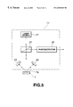
- FIG. 5 is a schematic illustration of an optical head of the servo signal writing apparatus in FIG. 3;
- FIG. 6 is a schematic illustration of an optical encoder and sensor to detect the moving position of the optical head in FIG. 5;
- FIG. 7 is an explanatory illustration of operations for servo signal write, by a first embodiment of servo signal writing apparatus according to the present invention, to a disc provided in the disc recording and/or reproducing apparatus;
- FIG. 8 is also an explanatory illustration of operations for servo signal write, by the first embodiment of servo signal writing apparatus, to the disc in the disc recording and/or reproducing apparatus;
- FIG. 9 is an explanatory illustration of operations for servo signal write, by the first embodiment of servo signal writing apparatus, to the disc in the disc recording and/or reproducing apparatus;
- FIG. 10 is also an explanatory illustration of operations for servo signal write, by the second embodiment of servo signal writing apparatus, to the disc in the disc recording and/or reproducing apparatus;
- FIG. 11 is an explanatory illustration of means for fixing, at a position, the magnetic head of the disc recording and/or reproducing apparatus
- FIG. 12 is also an explanatory illustration of operations for servo signal write, by the first embodiment of servo signal writing apparatus according to the present invention, to a disc provided in the disc recording and/or reproducing apparatus;
- FIG. 13 is also an explanatory illustration of operations for servo signal write, by the first embodiment of servo signal writing apparatus, to the disc in the disc recording and/or reproducing apparatus;
- FIG. 15 is an explanatory illustration of operations for servo signal write, by the second embodiment of servo signal writing apparatus, to the disc provided in the disc recording and/or reproducing apparatus;
- FIG. 16 is an explanatory illustration of operations for servo signal write, by the second embodiment of servo signal writing apparatus, to the disc provided in the disc recording and/or reproducing apparatus;
- FIG. 17 is an explanatory illustration of operations for servo signal write, by the second embodiment of servo signal writing apparatus, to the disc provided in the disc recording and/or reproducing apparatus.
- the disc recording and/or reproducing apparatus is shown in the form of a perspective view, and the servo signal writing apparatus according to the present invention is shown in the form of a schematic block diagram.
- the disc recording and/or reproducing apparatus is generally indicated with a reference 1
- the servo signal writing apparatus is generally indicated with a reference 10 .
- the disc recording and/or reproducing apparatus 10 comprises an enclosure 2 , and a magnetic disc 3 , magnetic head 4 , magnetic head holding arm 5 and an arm support 6 provided inside the enclosure 2 .
- the disc recording and/or reproducing apparatus 10 has provided therein a disc-shaped recording medium, that is, the magnetic disc 3 , and writes data to the magnetic disc and/or read data from the magnetic disc 3 .
- the arm 5 holds at the free end thereof the magnetic head 4 which magnetically writes to the magnetic disc 3 an input signal supplied from outside the disc recording and/or reproducing apparatus 1 .
- the magnetic head holding arm 5 has a pivot 5 a provided at a position near the base thereof, and is supported by the arm support 6 to be rotatable about the pivot 5 a .
- the arm support 6 incorporates a voice coil motor, for example. When supplied with a drive current, the voice coil motor drives the arm 5 .
- the arm 5 is turned about the pivot 5 a in a plane parallel to the signal recording surface of the magnetic disc 3 to move the magnetic head 4 held at the free end of the arm 5 in a plane parallel to the signal recording surface of the magnetic disc 3 .
- the magnetic head 4 can be moved radially of the magnetic disc 3 from the lead-in area to the lead-out area, or vice versa, of the magnetic disc 3 , to cover the entire recording surface of the magnetic disc 3 in writing and/or reading data to and/or from the recording surface.
- the turning range of the arm 5 is also a range in which the magnetic head 4 can be moved in a plane parallel to the recording surface of the magnetic disc 3 from the lead-in area to the lead-out area on the magnetic disc 3 .
- the arm 5 can be turned through an angle which varies depending upon the length of the arm 5 itself and size of the magnetic disc 3 .
- the arm turning angle is about 30°, for example.
- the disc recording and/or reproducing apparatus 1 comprises a scale 7 installed on the arm 5 near the free end of the latter 5 , for example.
- the scale 7 has a diffraction grating 7 a formed on a side thereof parallel to the side thereof fixed to the arm 5 .
- the scale 7 is turned along with the magnetic head 4 in a plane parallel to the signal recording surface of the magnetic head 3 .
- the diffraction grating 7 a provides for a position information indicative of a disc-radially moving position of the magnetic head 4 and which can be detected by means of a laser light irradiated thereon.
- the diffraction grating 7 a formed on the scale 7 can be read from outside the enclosure 2 of the disc recording and/or reproducing apparatus 1 .
- this reading of the diffraction grating 7 a can be attained by forming a portion of the enclosure 2 opposite to the diffraction grating 7 a on the scale 7 from a transparent material such as acryl or glass.
- FIG. 4 is a schematic illustration of a magnetic head holding arm of the disc recording and/or reproducing apparatus in FIG. 3 .
- the diffraction grating 7 a formed on the scale 7 has a width L smaller than a movable range X of the arm 5 at the position thereof where the scale 7 is installed.
- the magnetic head 4 can be moved from the lead-in area to the lead-out area on the magnetic disc 3 or vice versa (the arm 5 can be turned through an angle of about 30°, for example) to fully cover the recording area on the magnetic disc 3 in writing and/or reading data to and/or from the magnetic disc 3 .
- the servo signal writing apparatus 10 comprises an optical head 11 to irradiate a laser light onto the diffraction grating 7 a on the scale 7 and detect a reflected part of the laser light from the diffraction grating 7 a , an optical head support 12 to support the optical head 11 to be movable, a position signal detector 13 to generate, based on the detection signal from the optical head 11 , a position signal indicative of a moving position of the magnetic head 4 , a magnetic head drive controller 14 to drive the arm 5 to move the magnetic head 4 , an optical head drive controller 15 to drive the optical head support 12 to move the optical head 11 , a clock detecting head 16 , and a main controller 17 incorporating a memory 17 a.
- the optical head 11 irradiates a laser light onto the diffraction grating 7 a on the scale 7 , detects a reflected part of the laser light from the diffraction grating 7 a , and supplies a detection output to the position signal detector 13 .
- the optical head 11 comprises a laser source 21 to emit a laser light (incident laser light), a photodetector 22 to detect a reflected laser light and convert it to an electrical signal, a beam splitter 23 to pass the incident laser light, project it onto the diffraction grating 7 a on the scale 7 and reflect the reflected laser light from the diffraction grating 7 a on the scale 7 for projection to the photodetector 22 , and two mirrors 24 and 25 to diffract the reflected laser light twice.
- the laser light beams diffracted twice by the two mirrors 24 and 25 interfere with each other to yield a reflected laser light which is to be detected by the photodetector 22 .
- the scale 7 on it is moved along with the magnetic head 4 .
- the phase of the diffracted reflected laser light from the diffraction grating 7 a varies depending upon the disc-radial position of the magnetic head 4 . Therefore, by detecting the phase component of the laser light, it is possible to detect the moving position of the magnetic head 4 .
- the optical head 11 is supported by the optical head support 12 and is turned in a plane parallel to the signal recording surface of the magnetic disc 3 .
- the pivot 12 a of the optical head 11 is aligned with the pivot 5 a of the arm 5 , and thus the optical head 11 has a same radius of rotation as the scale 7 . Therefore, the optical head 11 is turned to delineate a similar orbit to that of the moving orbit of the scale 7 . For this reason, the optical head 11 can be moved to a position where it can irradiate a laser light onto the diffraction grating 7 a even when the arm 5 of the disc recording and/or reproducing apparatus 1 is turned. It should be noted that the optical head support 12 moves the optical head 11 to a predetermined position under the control of the main controller 17 which will further be described later.
- the position signal detector 13 is supplied with a detection output from the optical head 11 .
- the position signal detector 13 detects a changed phase component from the detection output to determine a disc-radial moving position of the magnetic head 4 , and supplies that position as a position signal to the main controller 17 .
- the magnetic head drive controller 14 is supplied with a magnetic head drive signal from the main controller 17 and supplies the voice coil motor in the arm support 6 with a drive current based on the supplied magnetic head drive signal to drive the arm 5 , thereby moving the magnetic head 4 to a predetermined disc-radial position.
- the optical head drive controller 15 is supplied with an optical head drive signal from the main controller 17 to drive the optical head support 12 based on the supplied optical head drive signal, to thereby move the optical head 11 to a predetermined position.
- the clock detecting head 16 detects, for example, a clock mark previously recorded in the lead-out area of the magnetic disc 3 and which indicates a rotational position of the magnetic disc 3 , and supplies a detection signal to the main controller 17 .
- the main controller 17 is supplied with a position signal from the position signal detector 13 to generate a magnetic head drive signal based on the supplied position signal, and supplies the magnetic head drive signal to the magnetic head drive controller 14 which will then control the magnetic head position by driving the magnetic head 4 to a predetermined position radially of the magnetic disc 3 based on the magnetic head drive signal. Since the servo signal writing apparatus 10 detects a position information indicated by the diffraction grating 7 a on the scale 7 and forms a servo loop to drive the arm 5 holding the magnetic head 4 , thereby controlling the position of the magnetic disc 3 , it can stably control the magnetic head position.
- the main controller 17 detects a rotational position of the magnetic disc 3 based on a clock mark detected by the clock detecting head 16 , and provides, each time the magnetic disc 3 turns a predetermined angle, a servo signal write control that a servo signal being a predetermined signal pattern is written to the magnetic disc 3 .
- the main controller 17 allows to write servo signals each time the magnetic disc 3 has reached an angle of 45° of turn, thereby writing 8 servo signals per full track.
- the main controller 17 supplies an optical head drive signal to the optical head drive controller 15 to control the optical head position by moving the position where the optical head 11 detects the diffraction grating 7 a on the scale 7 . It should be noted that the main controller 17 may use a position signal detected from the diffraction grating 7 a on the scale 7 to control the position of the optical head 11 .
- an optical encoder or sensors for example may be used to detect the current position and moving distance of the optical head 11 .
- the servo signal writing apparatus may adopt, for example, an optical encoder 33 comprising an optical scale 31 installed on the pivot of the optical head support 12 supporting the optical head 11 , and a photodetector 32 which irradiates a laser light to the optical scale 31 and detects the position of the optical head 11 , as shown in FIG. 6 A.
- the servo signal writing apparatus 10 may use a plurality of sensors 35 , 36 and 37 , as shown in FIG. 6B, each of which is responsive to an object 34 provided on the optical head 11 when the object has come to the proximity of the sensor.
- the servo signal writing apparatus 10 can detect a moving distance of the optical head 11 and control the moving position of the optical head 11 accurately.
- the servo signal writing apparatus 10 according to the present invention has not to control the position of the optical head 11 based on the track pitch of the magnetic disc 3 but can control the position of the optical head 11 without detection of that position.
- the servo signal writing apparatus 10 constructed as in the foregoing can move the magnetic head 4 radially of a magnetic disc 3 provided in the disc recording and/or reproducing apparatus 1 and in which no servo signal is yet written at every track pitch, and thus write servo signals supplied from outside to all tracks in the signal recording area on the magnetic disc 3 .
- the recorded width L of the diffraction grating 7 a formed on the scale 7 provided on the arm 5 of the disc recording and/or reproducing apparatus 1 is smaller than the turning distance X of the arm 5 at the portion thereof where the scale 7 is installed. That is, the position information indicated by the diffraction grating 7 a formed on the scale 7 does not cover all the disc-radial positions of the magnetic head 4 but indicates only the position information over some of the disc-radial positions of the magnetic head 4 . Therefore, the servo signal writing apparatus 10 functions to write a servo signal to each of all tracks in the signal recording area on the magnetic disc 3 as will be described herebelow:
- FIGS. 7 to 10 and FIGS. 12 to 13 schematically show the magnetic head 4 and scale 7 as if they were in contact with each other.
- this illustration is intended for the convenience of explaining the geometrical relation between the magnetic head 4 and scale 7 in the disc-radial direction and this illustration will not limit the geometrical relation between the magnetic head 4 and scale 7 in the servo signal writing apparatus 10 according to the present invention. This is also true with FIGS. 15 to 17 .
- the magnetic head 4 and scale 7 are moved to the inner edge of the lead-in area on the magnetic disc 3 .
- the optical head 11 is moved to a position where the laser light is irradiated to the innermost edge of the lead-out area of the magnetic disc 3 , the optical head 11 is stopped at that position.
- the main controller 17 will control the moving position of the magnetic head 4 and scale 7 based on a position signal detected from the diffraction grating 7 a to move the magnetic head 4 one by one track pitch.
- the main controller 17 has the magnetic head 4 write a servo signal to each track while the magnetic head 4 and scale 7 are being moved one by one track pitch.
- the main controller 17 will have the magnetic head 4 stop writing a servo signal once, determine a current position of the disc-radial position of the magnetic head 4 based on the detected position signal, and store the value of the present position into the memory 17 a.
- the main controller 17 will detect the position signal again after the magnetic head 4 has been fixed to determine the disc-radial position of the magnetic head 4 , and store the position into the memory 17 a.
- the main controller 17 will control the positions of the magnetic head 4 and scale 7 based on a position signal detected from the diffraction grating 7 a as well as on the position set in the memory 17 a to move the magnetic head 4 and scale 7 one by one track pitch,
- the main controller 17 will have the magnetic head 4 write a servo signal to each track while the magnetic head 4 and scale 7 are being moved one by one track pitch.
- the servo signal writing apparatus 10 moves the scale 7 and optical head 11 repeatedly as in the above to write servo signals down to the last track on the magnetic disc 3 .
- the number of times by which the optical head 11 is moved varies depending upon the ratio between the length of the diffraction scale 7 a formed on the scale 7 and the moving distance of the scale 7 when the arm 5 is turned over the magnetic disc 3 .
- the scale 7 may be designed to have approximately a quarter of the radius of the magnetic disc 3 for the optical head 11 to be moved 4 times in total.
- the servo signal writing apparatus 10 can be controlled from outside the disc recording and/or reproducing apparatus 1 to write a servo signal to each of all tracks in the signal recording area on the magnetic disc 3 .
- the disc recording and/or reproducing apparatus 1 it is possible in the disc recording and/or reproducing apparatus 1 according to the present invention to avoid the degradation, due to the mass of the scale 7 , of the mechanical frequency characteristic when the magnetic head 4 is moved, and the increase in power consumption, due to the mass of the scale 7 , when the magnetic head 4 is moved, thus permitting to stably control the position of the magnetic head 4 for writing and/or reading data to and/or from the magnetic disc 3 .
- the servo signal writing apparatus 10 the accuracy of writing servo signals to the magnetic disc 3 can be prevented from being degraded due to the difference in vibration characteristic between the magnetic head 4 and scale 7 , so that servo signals can be written with a high accuracy.
- the scale 7 can be designed small, it can be disposed at a position far from the pivot of the arm 5 , thereby allowing the scale 7 to turn more with a same angle of rotation than when it is disposed near the arm pivot. Therefore, the position of the magnetic head 4 can be controlled with a higher resolution when writing servo signals to the magnetic disc 3 which can thus record data with a higher density.
- the clock detecting head 16 is used to detect a clock mark recorded in the lead-out area on the magnetic disc 3 to detect the rotational position of the magnetic disc 3 .
- the rotational position of the magnetic disc 3 may be detected by any other means.
- a clock may be generated based on the rotation information of the spindle motor which drives to spin the magnetic disc 3 to detect the rotational position of the magnetic disc 3 .
- servo signals are written to the magnetic disc 3 beginning with the lead-in area.
- the direction of servo signal recording to the magnetic disc 3 is not limited to the direction from the lead-in area to lead-out area, but it may be a direction from the lead-out area to lead-in area on the magnetic disc 3 .
- the servo signal writing apparatus 50 comprises a plurality of optical heads 51 , 52 and 53 in place of the optical head 11 and optical head support 12 to movably support the optical head 11 .
- the optical heads 51 , 52 and 53 are fixed by a support (not shown), for example.
- the optical heads 51 , 52 and 53 are turned about a same center of rotation as that of the scale 7 , and they are disposed on circles that are also the moving orbits of the scale 7 .
- the optical heads 51 , 52 and 53 are spaced by a distance I which is smaller than the width L of the diffraction grating 7 a formed on the scale 7 .
- the optical heads 51 , 52 and 53 are disposed in this order for example from the lead-in area on the magnetic disc 3 .
- the main controller 17 will move the magnetic bead 4 to the innermost track on the magnetic disc 3 and then write a servo signal to the track while detecting the position of the magnetic head 4 by the use of the optical head 51 .
- the main controller 17 will judge whether the laser light irradiated from the optical head 51 has moved to the inner edge of the scale 7 . When it determines that the laser light has moved to that edge, it will switch the optical disc 51 to the optical disc 12 .
- the optical head 52 is irradiating the laser light to the outer edge of the scale 7 .
- the main controller 17 will have the magnetic head 4 write a servo signal while detecting the position of the magnetic head 4 by the use of the optical head 52 .
- the servo signal writing apparatus 50 can detect the position of the magnetic head 4 by sequentially irradiating the laser beams from the optical heads 51 , 52 and 53 to the diffraction grating 7 a on the scale 7 even when the arm 5 of the disc recording and/or reproducing apparatus 1 is turned.
- the servo signal writing apparatus 50 makes it possible to design small the scale 7 which is to be installed to the arm 5 of the disc recording and/or reproducing apparatus 1 .
- the scale 7 can be provided near the magnetic head 4 .
- the variant of the servo signal writing apparatus 10 is generally indicated with a reference 60 .
- the servo signal writing apparatus 60 comprises two optical heads 61 and 62 and two optical head supports (not shown) to movably support the optical heads 61 and 62 , respectively, in place of the optical head 11 and the optical head support 12 to movably support the optical head 11 .
- Each of the optical heads 61 and 62 is supported by each of the optical head supports and turned in a plane parallel to the signal recording surface of the magnetic disc 3 .
- the optical heads 61 and 62 are turned about the center of rotation of the arm 5 along orbits generally same as that of the scale 7 . Namely, both the optical heads 61 and 62 are turned delineating similar orbits to that of the scale 7 .
- the laser light from them can be moved to a position where the laser light can be irradiated to the diffraction grating 7 a on the scale 7 even when the arm 5 of the disc recording and/or reproducing apparatus 1 is turned.
- the two optical heads 61 and 62 are turned without any mechanical interference with each other and along different orbits so that both can irradiate the laser beams to the scale 7 .
- the main controller 17 For the servo signal writing apparatus 60 to write servo signals to the magnetic disc 3 , the main controller 17 will first move the magnetic head 4 and scale 7 to the innermost track on the magnetic disc 3 as shown in FIG. 15 . Then it will have the magnetic head 4 write a servo signal to the track while detecting the position of the magnetic head 4 by the use of the optical head 61 . When the main controller 17 determines that the laser light irradiated from the optical head 61 has moved to the inner edge of the scale 7 , it will stop the magnetic head 4 and scale 7 from moving to stop the servo signal write once.
- the main controller 17 will control the arm 5 based on a position signal obtained by irradiating the laser light from the optical head 61 , to fix the magnetic head 4 .
- the main controller 17 With the magnetic head 4 fixed, the main controller 17 will move the optical head 62 to a position where the optical head 62 can irradiate the laser light to the outer edge of the scale 7 as shown in FIG. 16 .
- the main controller 17 will switch the optical head 61 to the optical head 62 to irradiate a laser light. Then the main controller 17 will write a servo signal while detecting the position of the magnetic head 4 by the optical head 62 .
- the main controller 17 will stop the magnetic head 4 and scale 7 from moving to stop the servo signal write once and fix the magnetic head 4 by the use of the optical head 62 . While the magnetic head 4 is fixed using the optical head 62 , the main controller 17 will move the optical head 61 to a position where the laser light from the optical head 61 can be irradiated to the outer edge of the scale 7 .
- the servo signal writing apparatus 60 can detect the position of the magnetic head 4 by sequentially irradiating the laser beams from the optical heads 61 and 62 to the diffraction grating 7 a on the scale 7 even when the arm 5 of the disc recording and/or reproducing apparatus 1 is turned.
- using the servo signal writing apparatus 60 makes it possible to design small the scale 7 which is to be installed to the arm 5 of the disc recording and/or reproducing apparatus 1 .
- the scale 7 can be provided near the magnetic head 4 .
- the magnetic head 4 can be fixed by the user of another optical head not being moved.
- the servo signal writing apparatus 60 uses two optical heads 61 and 62 . However it should be noted that the number of the optical heads is not limited to two but the apparatus 60 may use three more optical heads.
- the disc-radial position of the read/write head is controlled by an external apparatus based on a position information recorded in a smaller range of the scale than the radial length of the signal recording area of the disc, to write servo signals to the disc.
- the scale can be designed small and installed near the read/write head. Therefore, in the disc recording and/or reproducing apparatus, the mechanical frequency characteristic of the read/write head can be stabilized, the drive current for driving the read/write head moving means, and thus it is possible to minimize a difference between the read/write head and scale, caused by a vibration at the time of writing servo signals to the disc.
- the scale is installed near the read/write head, thereby permitting to further stabilize the mechanical frequency characteristic of the read/write head.
- the disc recording and/or reproducing apparatus since the position information can be read from outside, servo signals can be recorded with no contact with an external apparatus.
- the disc recording and/or reproducing apparatus can record servo signals with a high resolution and accuracy and it can be manufactured with less costs.
- the position detecting means is moved correspondingly to a position on the disc where a servo signal is to be written to change the position where a position information is to be detected, thereby writing servo signals to the entire recording area on the disc in the disc recording and/or reproducing apparatus.
- the position information detecting means are selected according to a position on the disc where a servo signal is to be written to detect a position information, thereby writing servo signals to the entire recording area of the disc in the disc recording and/or reproducing apparatus.
- the servo signal writing apparatus can write servo signals to the disc in the disc recording and/or reproducing apparatus in which the scale can be designed small and installed near the read/write head. Therefore, in the disc recording and/or reproducing apparatus, the mechanical frequency characteristic of the read/write head can be stabilized, the drive current for driving the read/write head moving means, and thus it is possible to minimize a difference between the read/write head and scale, caused by a vibration at the time of writing servo signals to the magnetic disc.
- the servo signal writing apparatus can write servo signals to the disc in the disc recording and/or reproducing apparatus in which the scale is installed near the read/write head.
- the servo signal writing apparatus can control the position of the read/write head with a high resolution and further stabilize the mechanical frequency characteristic of the read/write head.
- servo signals can be recorded with no contact with the disc recording and/or reproducing apparatus.
- the servo signal writing apparatus can record servo signals to the disc in the disc recording and/or reproducing apparatus with a high resolution and accuracy and it can be manufactured with less costs.
Landscapes
- Moving Of The Head To Find And Align With The Track (AREA)
Abstract
Description
Claims (6)
Applications Claiming Priority (4)
| Application Number | Priority Date | Filing Date | Title |
|---|---|---|---|
| JP15967298A JP4174101B2 (en) | 1998-06-08 | 1998-06-08 | Servo signal writing device |
| JP15967398A JP4105290B2 (en) | 1998-06-08 | 1998-06-08 | Servo signal writing device |
| JP10-159673 | 1998-06-08 | ||
| JP10-159672 | 1998-06-08 |
Publications (1)
| Publication Number | Publication Date |
|---|---|
| US6583948B1 true US6583948B1 (en) | 2003-06-24 |
Family
ID=26486394
Family Applications (1)
| Application Number | Title | Priority Date | Filing Date |
|---|---|---|---|
| US09/326,276 Expired - Fee Related US6583948B1 (en) | 1998-06-08 | 1999-06-04 | Disc recording/reproducing apparatus and servo signal writing apparatus |
Country Status (1)
| Country | Link |
|---|---|
| US (1) | US6583948B1 (en) |
Cited By (7)
| Publication number | Priority date | Publication date | Assignee | Title |
|---|---|---|---|---|
| US20020021523A1 (en) * | 2000-04-28 | 2002-02-21 | Koh Ishizuka | Displacement detection apparatus, and magnetic recording apparatus and encoder using the displacement detection apparatus |
| US20020109931A1 (en) * | 2000-11-14 | 2002-08-15 | Stmicroelectronics S.R.I. | Read/write transducer for hard disk drives with optical position measuring system, and manufacturing process thereof |
| EP1612914A2 (en) * | 2004-06-24 | 2006-01-04 | Dr. Johannes Heidenhain GmbH | Voice coil motor and positioning apparatus including the same |
| US7365932B1 (en) | 2005-12-30 | 2008-04-29 | Western Digital Technologies, Inc. | Disk drive comprising an optical sensor for vibration mode compensation |
| US7480116B1 (en) * | 2006-01-20 | 2009-01-20 | Western Digital Technologies, Inc. | Disk drive employing coarse position feedback from mechanical position sensor to improve format efficiency |
| US7495857B1 (en) | 2005-12-30 | 2009-02-24 | Western Digital Technologies, Inc. | Servo writing a disk drive by writing spiral tracks using a mechanical position sensor |
| US7619844B1 (en) | 2005-12-30 | 2009-11-17 | Western Digital Technologies, Inc. | Disk drive comprising a mechanical position sensor to prevent a runaway condition |
Citations (3)
| Publication number | Priority date | Publication date | Assignee | Title |
|---|---|---|---|---|
| US5325349A (en) * | 1991-05-29 | 1994-06-28 | Sony Magnescale Inc. | Hard disc drive and a servo signal writing apparatus |
| US6005667A (en) * | 1996-07-23 | 1999-12-21 | Canon Kabushiki Kaisha | Optical displacement measurement apparatus and information recording apparatus |
| US6151185A (en) * | 1996-09-05 | 2000-11-21 | Canon Kabushiki Kaisha | Position detecting apparatus, positioning apparatus, and information recording apparatus using the same |
-
1999
- 1999-06-04 US US09/326,276 patent/US6583948B1/en not_active Expired - Fee Related
Patent Citations (3)
| Publication number | Priority date | Publication date | Assignee | Title |
|---|---|---|---|---|
| US5325349A (en) * | 1991-05-29 | 1994-06-28 | Sony Magnescale Inc. | Hard disc drive and a servo signal writing apparatus |
| US6005667A (en) * | 1996-07-23 | 1999-12-21 | Canon Kabushiki Kaisha | Optical displacement measurement apparatus and information recording apparatus |
| US6151185A (en) * | 1996-09-05 | 2000-11-21 | Canon Kabushiki Kaisha | Position detecting apparatus, positioning apparatus, and information recording apparatus using the same |
Cited By (11)
| Publication number | Priority date | Publication date | Assignee | Title |
|---|---|---|---|---|
| US20020021523A1 (en) * | 2000-04-28 | 2002-02-21 | Koh Ishizuka | Displacement detection apparatus, and magnetic recording apparatus and encoder using the displacement detection apparatus |
| US7054095B2 (en) * | 2000-04-28 | 2006-05-30 | Canon Kabushiki Kaisha | Displacement detection apparatus, and magnetic recording apparatus and encoder using the displacement detection apparatus |
| US20020109931A1 (en) * | 2000-11-14 | 2002-08-15 | Stmicroelectronics S.R.I. | Read/write transducer for hard disk drives with optical position measuring system, and manufacturing process thereof |
| US6924958B2 (en) * | 2000-11-14 | 2005-08-02 | Stmicroelectronics S.R.L. | Read/write transducer for hard disk drives with optical position measuring system, and manufacturing process thereof |
| EP1612914A2 (en) * | 2004-06-24 | 2006-01-04 | Dr. Johannes Heidenhain GmbH | Voice coil motor and positioning apparatus including the same |
| US7365932B1 (en) | 2005-12-30 | 2008-04-29 | Western Digital Technologies, Inc. | Disk drive comprising an optical sensor for vibration mode compensation |
| US7495857B1 (en) | 2005-12-30 | 2009-02-24 | Western Digital Technologies, Inc. | Servo writing a disk drive by writing spiral tracks using a mechanical position sensor |
| US7619844B1 (en) | 2005-12-30 | 2009-11-17 | Western Digital Technologies, Inc. | Disk drive comprising a mechanical position sensor to prevent a runaway condition |
| US7480116B1 (en) * | 2006-01-20 | 2009-01-20 | Western Digital Technologies, Inc. | Disk drive employing coarse position feedback from mechanical position sensor to improve format efficiency |
| US7701661B1 (en) | 2006-01-20 | 2010-04-20 | Western Digital Technologies, Inc. | Disk drive employing coarse position feedback from mechanical position sensor to improve format efficiency |
| US7760461B1 (en) | 2006-01-20 | 2010-07-20 | Western Digital Technologies, Inc. | Disk drive employing coarse position feedback from mechanical position sensor to improve format efficiency |
Similar Documents
| Publication | Publication Date | Title |
|---|---|---|
| US4884259A (en) | Optical memory disk and track access therefor | |
| US5339204A (en) | System and method for servowriting a magnetic disk drive | |
| US5059774A (en) | Seek and track control for a rectangular optical card handling apparatus | |
| US5138594A (en) | Reducing amplitude variations of optical disk readback signals and increasing reliability of track-crossing counts | |
| US4736353A (en) | Disc accessing using coarse and fine actuators with the fine actuator locked during coarse actuator movement | |
| US4837757A (en) | Optical recording/reproducing device | |
| US5325349A (en) | Hard disc drive and a servo signal writing apparatus | |
| JP2635610B2 (en) | Disk unit | |
| US5696742A (en) | Optical disk device for reproducing address information from wobbled groove | |
| US6583948B1 (en) | Disc recording/reproducing apparatus and servo signal writing apparatus | |
| US5513159A (en) | Device for selecting magnetic head to be operated together with an optical head | |
| JPH0512768B2 (en) | ||
| US5058092A (en) | Method for accessing a control track by positioning an optical head at the center of the control track | |
| US5627810A (en) | Recording/reproducing apparatus that forms read and write clock signals with differing frequencies from the servo clock signals | |
| KR100573625B1 (en) | Device equipped with control system, drive system, control method and drive system | |
| US6577581B2 (en) | Variable recording layer disk image pickup device | |
| EP1081691B1 (en) | Method and apparatus for measuring the eccentricity of disk | |
| EP0327033A2 (en) | Information processing apparatus | |
| JP4105290B2 (en) | Servo signal writing device | |
| JPH0834029B2 (en) | Disk device | |
| JP4174101B2 (en) | Servo signal writing device | |
| JPH06302135A (en) | Head positioning method and apparatus for information storage disk apparatus, and servo information writing method and writing apparatus using the same, slider, slider support member, magnetic disk apparatus | |
| US5648944A (en) | Recording/reproducing apparatus that utilizes the servo clock signals to form read and write clock signals with different frequencies | |
| US6747925B2 (en) | Method and system for generating a center error signal in an optical storage system | |
| JP2806128B2 (en) | Optical tape device and optical tape used in this device |
Legal Events
| Date | Code | Title | Description |
|---|---|---|---|
| AS | Assignment |
Owner name: SONY PRECISION TECHNOLOGY INC., JAPAN Free format text: ASSIGNMENT OF ASSIGNORS INTEREST;ASSIGNOR:TANIGUCHI, KAYOKO;REEL/FRAME:010229/0393 Effective date: 19990527 |
|
| FPAY | Fee payment |
Year of fee payment: 4 |
|
| FEPP | Fee payment procedure |
Free format text: PAYER NUMBER DE-ASSIGNED (ORIGINAL EVENT CODE: RMPN); ENTITY STATUS OF PATENT OWNER: LARGE ENTITY Free format text: PAYOR NUMBER ASSIGNED (ORIGINAL EVENT CODE: ASPN); ENTITY STATUS OF PATENT OWNER: LARGE ENTITY |
|
| AS | Assignment |
Owner name: SONY MANUFACTURING SYSTEMS CORPORATION,JAPAN Free format text: MERGER;ASSIGNOR:SONY PRECISION TECHNOLOGY INC.;REEL/FRAME:024225/0488 Effective date: 20040401 |
|
| FPAY | Fee payment |
Year of fee payment: 8 |
|
| AS | Assignment |
Owner name: MAGNESCALE CO., LTD., JAPAN Free format text: ASSIGNMENT OF ASSIGNORS INTEREST;ASSIGNOR:SONY MANUFACTURING SYSTEMS CORPORATION;REEL/FRAME:026613/0300 Effective date: 20110712 |
|
| AS | Assignment |
Owner name: MORI SEIKI CO., LTD., JAPAN Free format text: ASSIGNMENT OF ASSIGNORS INTEREST;ASSIGNOR:MAGNESCALE CO., LTD.;REEL/FRAME:031858/0817 Effective date: 20130930 |
|
| AS | Assignment |
Owner name: DMG MORI SEIKI CO., LTD., JAPAN Free format text: CORRECTIVE ASSIGNMENT TO CORRECT THE ASSIGNEE'S NAME PREVIOUSLY RECORDED ON REEL 031858 FRAME 0817. ASSIGNOR(S) HEREBY CONFIRMS THE ASSIGNMENT OF ASSIGNOR'S INTEREST;ASSIGNOR:MAGNESCALE CO., LTD.;REEL/FRAME:032462/0738 Effective date: 20130930 |
|
| REMI | Maintenance fee reminder mailed | ||
| LAPS | Lapse for failure to pay maintenance fees | ||
| LAPS | Lapse for failure to pay maintenance fees |
Free format text: PATENT EXPIRED FOR FAILURE TO PAY MAINTENANCE FEES (ORIGINAL EVENT CODE: EXP.) |
|
| FP | Lapsed due to failure to pay maintenance fee |
Effective date: 20150624 |
|
| STCH | Information on status: patent discontinuation |
Free format text: PATENT EXPIRED DUE TO NONPAYMENT OF MAINTENANCE FEES UNDER 37 CFR 1.362 |