US658263A - Wheel-plow. - Google Patents
Wheel-plow. Download PDFInfo
- Publication number
- US658263A US658263A US1067200A US1900010672A US658263A US 658263 A US658263 A US 658263A US 1067200 A US1067200 A US 1067200A US 1900010672 A US1900010672 A US 1900010672A US 658263 A US658263 A US 658263A
- Authority
- US
- United States
- Prior art keywords
- plow
- standard
- lever
- wheel
- frame
- Prior art date
- Legal status (The legal status is an assumption and is not a legal conclusion. Google has not performed a legal analysis and makes no representation as to the accuracy of the status listed.)
- Expired - Lifetime
Links
Images

Classifications
-
- A—HUMAN NECESSITIES
- A01—AGRICULTURE; FORESTRY; ANIMAL HUSBANDRY; HUNTING; TRAPPING; FISHING
- A01B—SOIL WORKING IN AGRICULTURE OR FORESTRY; PARTS, DETAILS, OR ACCESSORIES OF AGRICULTURAL MACHINES OR IMPLEMENTS, IN GENERAL
- A01B35/00—Other machines for working soil not specially adapted for working soil on which crops are growing
- A01B35/02—Other machines for working soil not specially adapted for working soil on which crops are growing with non-rotating tools
- A01B35/10—Other machines for working soil not specially adapted for working soil on which crops are growing with non-rotating tools mounted on tractors
Definitions
- EIILiTIIL m Remus P515115 00. PNoToLn'nu. WASNINGYON. n. c.
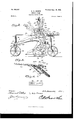
- My invention is an improved wheel-plow of the class known generally as three-wheel plows, in which a frame supported on wheels is designed to support the plow not only while elevated above the ground, but also in all of its various adjustments, and especially to support the plow in operation in order to lighten the draft thereof.
- One object of my invention is to provide a wheel-plow in which the plowshare is adapted to be adjusted pivotally on the standard and caused to operate at any desired inclination in the furrow.
- a further object of my invention is to pro vide a plow in which the share is adapted to be obliquely disposed to any desired degree with reference to the standard, so as to widen or narrow the furrow made by the plow at will.
- a further object of my invention is to pro'-' vide an improved lever and connections for raising and lowering the plow.
- a further object of my invention is to provide an improved lever and connections for tilting the plow on its standard.
- the supporting-frame 1 is provided on the" land side with the lateral projecting portions 2, on which is carried the seat-bar 3 and in which is mounted the crank-axle 4 of the land side supporting-wheel 5;
- a lever 6 is secured to and projects from said crank-axle and is secured at any desired adjustment by means of the spring-pressed detent 7, which engages a segment rack-plate 8, with which the outer side of the part 2 of the frame is provided.
- the side bar 9 of the frame is vprovided at its front end with a lateral extension 10, forming a bracket, to which is bolted a vertical tubular bearing 11 for the standard-bar 12, which is swiveled therein, has its lower end outturned to form the supporting-spindle for the inclined front furrowwheel 13, and at its upper end is provided with the tiller-head 14.
- a vertical tubular bearing 15 is bolted at the rear end of the frame 1 is bolted a vertical tubular bearing 15, in which is likewise swiveled a similar standard-bai- 16, on the lower portion of which is mounted an inclined furrow-wheel 17 and at the upper end of which is a tillerbar 18, on which is secured-a yoke-plate 19.
- Said yoke-plate is provided with bearings 20 for a connecting-rod 21, the front end of which is pivotally connected to the inner side of the tiller-head 14:, as shown.
- a coiled extensile spring 22 on the said connectingrod 21 bears between the forward bearing 20 and a tension-nut 23, which is screwed on the rear threaded portion of said connectingrod, the function of said spring being to normally restrain longitudinal movement of therod 21 and to permit either of the standardbars 13 16 to turn so as to clear their respective wheels of obstructions which may be encountered.
- the plow-beam 24 is of the steel or iron beam type in which the standard 25 is formed integrallytherewith; but for the purposes of this specification said standard and said beam are separately designated.
- the front end of the standard is provided with a lateral clevis 26, and immediately in rear of said clevis is an inverted U -shaped shoe 27 which is bolted to the plow-beam, as at 28, and extends above the beam for a suitable distance, and through said shoe and the front ends of the bars which form the sides of the frame llextends a bolt 29, which forms a pivotal. connection between the front end of the beam and the front end of the supporting-frame 1.
- the landside-plate 30 of the plowshare 31 is pivotally connected to the lower end of the stand.-
- a brace-bar'36 has one end bolted to the under side of the moldboard, as at 37, and.:the .othen endpthereof secured to the bar 33 by the bolt 35.
- the opening in. the lower end of the standard, through which1the pivotal bolt26 passes-, is sufliciently large to enable. thesaid. boltzto play loosely in said opening, and.
- the plowshare is adapted to be adgjnsted'obliquely with reference to its standard. and. the beann A wedge-key 38 is interposed between the lower portion of the standard25and theopl posing side of the landside" 30,.saidiwedge key. being securedin position by. thebolt26 and a bolt 39, which pass through slotted: openings 40, with. which said wedge-key. is provided.
- the bolts26t 39 are tights ened, so as tofirmly seattheakey in place.
- theplowshare is adapted to be disposedihorizontally or. tilted or inclined to. any appropriate angle vertically as. may be desired.
- I provide a lever 41, whichis mounted. on the frame 1, as at 42, and is-providedwith a.rearwardly-extending crank-armew; which is connected to the plow-standardby. alink. 43, said link being pivotally connected tosaid" cranksarm and to said. standard, asat; 4. L. 45.
- the lever 41 has avertically-movable.detent.
- the said cam has an operating-lever 51, which projects therefrom.
- brace-bar connect meanstosecure said plowshare .wheni adj ustf to its pivot, substantially as describedi liwith the la-ndside anda.
- A .plow. havinga share adaptedto beadjusted with. relation with its standard, both in vertical and. horizontal. planes, substantially asdescribed.
- a siipporting-frame a plow having its beam pivotally connected to the supporting-frame, said plow being pivoted to the lower end of the standard, a lever, to raise and lower said 5 plow, an adjusting-lever to set the plow on its pivot with relation to the standard, said adjusting-lever having an arm, a link pivotally connected to the said plow, and a crosshead to which the upper end of said link is 10 pivoted, said cross-head being adjustable on the said arm of said adj usting-lever, snbstan tially as described.
Description
0 U W m: L p 0 8 d e t n e t a w 9 Bill WW m w; HL Ann .w D h w. M 3 6 0o 5 5 0 N 2 Sheets+8heet I.
(No Model) 1 v H W N Wflgessas E $4M his eAHm e ys Patented Sept. l8, I900.
D. A. H OUSEB.
. WHEEL PLOW.
(Application filed Mam-.129; 1900.:
2 Sheets-Sheet 2.
(No Model.)
EIILiTIIL m: Remus P515115 00. PNoToLn'nu. WASNINGYON. n. c.
UNITE STATES PATENT 'OFFICE.
DAVID A. HOUSER, OF OTTAWA, KANSAS.
WHEEL-PLOW.
S PECIFICATION forming part of Letters Patent No. 658,263, dated September 18, 1900.
Application filed March 29,1900. Serial No. 10,672. \No model.)
T0 at whom it mag concern:
Be it known that 1, DAVID A. HOUSER,a citizen of the United-States, residing at Ottawa, in the county of Franklin and State of Kansas, have invented a new and useful Whee1- Plow, of which the following is a specification.
My invention is an improved wheel-plow of the class known generally as three-wheel plows, in which a frame supported on wheels is designed to support the plow not only while elevated above the ground, but also in all of its various adjustments, and especially to support the plow in operation in order to lighten the draft thereof.
One object of my invention is to provide a wheel-plow in which the plowshare is adapted to be adjusted pivotally on the standard and caused to operate at any desired inclination in the furrow.
A further object of my invention is to pro vide a plow in which the share is adapted to be obliquely disposed to any desired degree with reference to the standard, so as to widen or narrow the furrow made by the plow at will.
A further object of my invention is to pro'-' vide an improved lever and connections for raising and lowering the plow.
A further object of my invention is to provide an improved lever and connections for tilting the plow on its standard.
With these and other objects in view my invention consists in the peculiar construction and combination of devices hereinafter fully set forth, and pointed out in the claims.
The supporting-frame 1 is provided on the" land side with the lateral projecting portions 2, on which is carried the seat-bar 3 and in which is mounted the crank-axle 4 of the land side supporting-wheel 5; A lever 6 is secured to and projects from said crank-axle and is secured at any desired adjustment by means of the spring-pressed detent 7, which engages a segment rack-plate 8, with which the outer side of the part 2 of the frame is provided. The side bar 9 of the frame is vprovided at its front end with a lateral extension 10, forming a bracket, to which is bolted a vertical tubular bearing 11 for the standard-bar 12, which is swiveled therein, has its lower end outturned to form the supporting-spindle for the inclined front furrowwheel 13, and at its upper end is provided with the tiller-head 14. At the rear end of the frame 1 is bolted a vertical tubular bearing 15, in which is likewise swiveled a similar standard-bai- 16, on the lower portion of which is mounted an inclined furrow-wheel 17 and at the upper end of which is a tillerbar 18, on which is secured-a yoke-plate 19. Said yoke-plate is provided with bearings 20 for a connecting-rod 21, the front end of which is pivotally connected to the inner side of the tiller-head 14:, as shown. A coiled extensile spring 22 on the said connectingrod 21 bears between the forward bearing 20 and a tension-nut 23, which is screwed on the rear threaded portion of said connectingrod, the function of said spring being to normally restrain longitudinal movement of therod 21 and to permit either of the standardbars 13 16 to turn so as to clear their respective wheels of obstructions which may be encountered.
It will be understood that by means of the independently pivoted standards of the wheels 13 17 said wheels act as caster-wheels to permit the wheel-plow to be drawIi-in any desired direction, and, moreover, that when said plow is turned said wheels adjust themselves concentrically to the vertical axis of the land-wheel 5 and enable the plow to be turned in a very short space.
.The plow-beam 24 is of the steel or iron beam type in which the standard 25 is formed integrallytherewith; but for the purposes of this specification said standard and said beam are separately designated. The front end of the standard is provided with a lateral clevis 26, and immediately in rear of said clevis is an inverted U -shaped shoe 27 which is bolted to the plow-beam, as at 28, and extends above the beam for a suitable distance, and through said shoe and the front ends of the bars which form the sides of the frame llextends a bolt 29, which forms a pivotal. connection between the front end of the beam and the front end of the supporting-frame 1. The landside-plate 30 of the plowshare 31 is pivotally connected to the lower end of the stand.-
Itwill be understood; from. the foregoing description and by reference to the drawingsthat by reason of the plowshare being pivot ally connected toits standard-.onfthe bolt 26* theplowshare is adapted to be disposedihorizontally or. tilted or inclined to. any appropriate angle vertically as. may be desired. To accomplish vertical adjustment of theplow, I provide a lever 41, whichis mounted. on the frame 1, as at 42, and is-providedwith a.rearwardly-extending crank-armew; which is connected to the plow-standardby. alink. 43, said link being pivotally connected tosaid" cranksarm and to said. standard, asat; 4. L. 45. The lever 41 has avertically-movable.detent. 46, which engagesa segment-.raek. 4.7 and: is; adapted to secure the lever: at anyadjust ment, and thus support theplow. when: the same is raised or. lowered, and the said detent 46 is connected to a grip 4.8-, with which the lever 41 is provided, by a link 49. By means of, the grip thedetent may bemoved into or out of engagement with the-segment-raok, as Will be readily understood. In order to adapt. the lever to be firmly. lockediwhemthe plow has been adjusted vertically in. operative. position, I provide a cam 50, which ispivoted. tothe lever 41 at a point immediately below thegripAS andis adapted to bel-turned so asi toengage said grip and lockthesame against ceases movement, and; hence prevent the detent from being displaced from the notch in the segment with which it is engaged. The said cam has an operating-lever 51, which projects therefrom.
To enable the plow to be tilted on its pivotbolt 26, I-provide a lever 52, which is fulcrumed on the bolt 42, that serves also as the i pi.vot .for the lever 41, and said lever 52 has a rearwardly-extendin g crank-arm 53, on which is a cross-head 54, that is adapted to be adj nsted to any required position. on said cranlv arm and has a set-screw 55, whereby it may be set when-adjusted. A link-bar 56 is piv= otally connected to the said cross-head and i to the bar 33 attheheel of theplow, as shown. 3 Theleven i -l carriesra segment-rack 57., which is engagediby-aspring-pressed detent 58, with which lever. 52 is proyidedk, and. hence said lever 52 maybe locked at any required ad'- justment when the plowshare is set or inclined on the standard.
Having thus describeds my invention, I claim-- 1. In a wheehplow theicombination witha supporting-frame, of a. plow having itsbeam ptvotally connected: to. the frame. and the adapted; to be inclined; vertically adjusted with relation to said standard;. and the. adjusting-levers having their pivots in line with each. other-,onaef said adjlisting-leversbei'ng connected to the=plowsbeam .andtlieotlier being adapted to. adj net the :plowshare on. its pivot, substantially as described;
2:. A plow-having the plowshare piyotally connected} to i the standard, on one side thereof, and therebyadapted. to. betilted; in the direction of itslength, said sharebeing also adapted tor tnrni laterally on v said. pivot,.in combination witha key wedge between the Flandside. and the plowstandard, whereby said plowshare may be.also obliquelyadjusted with relation 130111116 standard, substantially-as described;
nectedy to thest-andard: and, adapted to tu'rn laterally on. said: pivot in combinationwith meanstosecure said plowshare .wheni adj ustf to its pivot, substantially as describedi liwith the la-ndside anda. brace-bar connect:
;tion. with. the standard to. which. the share is pivoted, said standard being between the jlandside'. and; supporting-bar, means to. tilt .and verticallyadjust the share on its pivot iand means to set .saidzplow on said. pivot at entangle .to.the line .of draft, substantially. as ;described-..
5. A=.plow. havinga share adaptedto beadjusted with. relation with its standard, both in vertical and. horizontal. planes, substantially asdescribed.
share pivotally connectedi to the standard and.
1 3. A plow having. its. share pivotally conedaboth laterally. and vertically with relation i 4:. A-plow having the share-providedwith; atbarsecured to and substantially parallel ling said: barto the moldboard,incombinm 6. In. awheelsplow, the. combination. with:
a siipporting-frame, a plow having its beam pivotally connected to the supporting-frame, said plow being pivoted to the lower end of the standard, a lever, to raise and lower said 5 plow, an adjusting-lever to set the plow on its pivot with relation to the standard, said adjusting-lever having an arm, a link pivotally connected to the said plow, and a crosshead to which the upper end of said link is 10 pivoted, said cross-head being adjustable on the said arm of said adj usting-lever, snbstan tially as described.
In testimony that I claim the foregoing as my own I have hereto affixed my signature in the presence of two witnesses.
DAVID A. HOUSER.
Witnesses:
JOHN H. HARRISON, JOHN H. HoUsER.
Priority Applications (1)
| Application Number | Priority Date | Filing Date | Title |
|---|---|---|---|
| US1067200A US658263A (en) | 1900-03-29 | 1900-03-29 | Wheel-plow. |
Applications Claiming Priority (1)
| Application Number | Priority Date | Filing Date | Title |
|---|---|---|---|
| US1067200A US658263A (en) | 1900-03-29 | 1900-03-29 | Wheel-plow. |
Publications (1)
| Publication Number | Publication Date |
|---|---|
| US658263A true US658263A (en) | 1900-09-18 |
Family
ID=2726832
Family Applications (1)
| Application Number | Title | Priority Date | Filing Date |
|---|---|---|---|
| US1067200A Expired - Lifetime US658263A (en) | 1900-03-29 | 1900-03-29 | Wheel-plow. |
Country Status (1)
| Country | Link |
|---|---|
| US (1) | US658263A (en) |
-
1900
- 1900-03-29 US US1067200A patent/US658263A/en not_active Expired - Lifetime
Similar Documents
| Publication | Publication Date | Title |
|---|---|---|
| US658263A (en) | Wheel-plow. | |
| US1200107A (en) | Engine gang-plow. | |
| US553100A (en) | Ustvz | |
| US131404A (en) | Improvement in cultivators | |
| US302481A (en) | Sulky-plow | |
| US387484A (en) | Sulky-plow | |
| US585049A (en) | Pulverizer | |
| US999817A (en) | Plow. | |
| US786427A (en) | Disk plow. | |
| US213623A (en) | Improvement in gang-plows | |
| US666949A (en) | Plow. | |
| US132842A (en) | Improvement in gang-plows | |
| US184425A (en) | Improvement in gang-plows | |
| US1106119A (en) | Gang-plow. | |
| US311016A (en) | linham | |
| US1019803A (en) | Cultivator. | |
| US467020A (en) | Harrow attachment for plows | |
| US44924A (en) | Improvement in gang-plows | |
| US302731A (en) | huddlestone | |
| US306342A (en) | meagher | |
| US353628A (en) | Wheel-plow | |
| US736662A (en) | Sulky-plow. | |
| US389705A (en) | Territory | |
| US315169A (en) | Sulky-plow | |
| US246666A (en) | Worth |